






Abstract
For dexterous interactive manipulations, the robot end-effector must follow a motion trajectory and exert an appropriate force against the contacted environment to provide a specified dynamic working compliance. Hence, the robotic impedance is an important function for future applications of intelligent robots. For this purpose, a generalized hybrid control strategy is developed to monitor the motion trajectory and the end-effector interaction force in the task space simultaneously. Here, the Altera development board-based embedded robotic control structure is constructed and the related intelligent position/force hybrid control strategy is developed. A new model-free intelligent fuzzy sliding mode controller is designed to monitor the force and position specifications for hybrid impedance control purposes. It has the advantages of one-dimensional fuzzy control features with online gain scheduling and sliding mode stability. A force sensor is installed in a Mitsubishi robot end-effector to measure the dynamic contact force during compliant operations. The experimental results show that the dynamic performance of the proposed hybrid impedance control system can reach the contouring error of less than 1 mm and a contact force error of less than 3 N, respectively.
Introduction
When a robot manipulator is in contact with a constraining surface, a contact force is generated between the end-effector and the environment. The force exerted by the robot on the environment depends on how great the difference is between the end-effector position and its target position, which is physically constrained by the environment. Hence, the contact force can be regulated by appropriately adjusting the end-effector position. However, the robotic contact force control has been known to be one of the more complicated control problems, especially when a robot needs to track a desired trajectory and maintain a specified interactive force within the constraint environment. Typical force control applications are peg-in-hole operations, deburring, grinding, assembly, machine–human interaction, etc. These robotic impedance control problems are not yet well solved. One most frequently used approach is to adjust the robot end-effector position in response to the sensed contact force in such a way that a target impedance relationship is satisfied. This is the well-known impedance force control concept (Hogan, 1985). This approach is different from the hybrid force control technique, which controls the position and the force separately in their own controllable directions (Raibert and Craig, 1981). This impedance control concept is widely employed in the literature for robotic hybrid position and force control (Anderson and Spong, 1987; Liu and Goldenberg, 1991).
After the pioneering work of Hogan’s impedance control, there are still several major research issues to be solved. Contact stability has been analysed for the impedance control stable execution (Colgate and Hogan, 1989), and force control has been analysed based on linear model (Goldenberg, 1992). In addition to those efforts, various control algorithms have been proposed. One is called torque-based impedance force control (Hogan, 1985). In this approach, the torque information is assumed to be available, so that the impedance function can implicitly be implemented inside the control loop. For position-based impedance force control (Lawrence, 1988), information on the control input torque is not available, so the impedance function is explicitly implemented outside the position control loop. The latter impedance control approach has the advantage of easy implementation on an existing position-controlled robot system. However, the position controller should have highly accurate control performance to achieve the desired force control objective. The design of these two impedance control laws is straightforward if the models of the robot manipulator and the environment information are well known (Spong and Vidyasagar, 1989). Accurate knowledge of the environment stiffness is very important to determine the robot target trajectory to attain the desired compliance. Uncertainties in these models will degrade the system performance. In practice, the complete dynamic model of a robot cannot be established exactly, and the environment stiffness cannot be estimated accurately either.
Lasky and Hsia (1991) proposed an inner/outer loops control scheme where the robot dynamics uncertainties were compensated for by a robust position control algorithm in the inner loop and the estimated environment position was modified using integral control of the force tracking error in the outer loop. The generalized impedance control based on a dynamic relationship between position error and force error was proposed to deal with the unknown environment stiffness (Lee and Lee, 1991). An adaptive technique has been proposed to estimate the environment stiffness or adjust controller gains for compensating for unknown environment stiffness based on force tracking error information (Colbaugh and Elgelmann, 1994; Seraji, 1994; Seraji and Colbaugh, 1993). A simple trajectory modification scheme was proposed to compensate for the robot dynamics uncertainties (Lasky and Hsia, 1991), and the unknown environment stiffness was replaced by contact force information (Jung et al., 1995). Later analysis showed that accurate force tracking is not always guaranteed unless the accuracy of the estimated environment position is within certain bounds (Jung and Hsia, 1995). In addition, an intelligent force control algorithm using the neural network scheme was proposed to compensate for the uncertainties (Jung and Hsia, 1998, 2000; Jung et al., 2001). Fuzzy-neuro techniques have been used to deal with the robotic force control operation of geometrically unknown objects (Kiguchi and Fukuda, 2000; Tao and Luh, 1993).
The adaptive impedance control technique (Colbaugh et al., 1993) proposed a function mapping of a Cartesian space control input to joint control torque, so that the robot dynamic model is not required for the position/force control. In the literature, many studies also have been performed to solve the problem of environment stiffness uncertainty, by employing a separate trajectory modification control loop with integral control (Lasky and Hsia, 1991), by using adaptive control to generate reference position based on force tracking error (Seraji and Colbaugh, 1993; Colbaugh and Elgelmann, 1994), or by using adaptive control to adjust controller gains based on force errors (Seraji, 1994). These techniques will increase the complexity of the system dynamics and require special attention to system stability.
This paper provides a simple control structure to achieve the impedance force tracking control objective. The proposed robot hybrid impedance controller has model-free intelligent features and it is robust with respect to uncertainties in the robot dynamic model and environment position and stiffness. The force error and position error were minimized directly by using an individual fuzzy sliding mode controller when the robot is manipulated to track a desired trajectory on an unknown environment. Environmental stiffness knowledge is not required to implement this algorithm. The proposed control law is very simple so that it can be easily implemented in embedded robot control systems. The field-programmable gate array (FPGA)-based control system is constructed for a 5-DOF Mitsubishi robot. Experimental results of force monitoring control with fixed positions and trajectory tracking cases are presented to evaluate the performance of this novel simple control scheme.
System structure
The retrofitted robotic control structure with Atera Nios II embedded development kit is shown in Figure 1. The Nios II development board is employed to send digital signals to the lab-made DC servo motor drivers with an LMD18200 IC for actuating each joint motor of the robotic system, and to detect each joint motor angular position to constitute a multi-inputs closed-loop control system. This Nios II development board has an embedded Atera Stratix system-on-a-programmable-chip (SOPC). Here, Verilog HDL (Hardware Description Language) is selected to code the hardware circuits of this embedded robotic control system. The main servo control system can be divided into FPGA internal hardware circuits and Nios II micro-processor software programs two parts. The main functions of FPGA hardware circuits are motor optical encoder decoding, limit switch detecting, pulse width modulation (PWM) generating. The functions of the Nios II micro-processor software programs are communication with a PC using UART, robotic inverse kinematics calculation, robotic motion trajectory planning and robotic motion control schemes. A four-bit delay filter with four serial D-type flip-flops is designed to suppress the high-frequency noise of the feedback signals. A 13-bit control signal is used to regulate the duty circle of the servo motor PWM signal. The robotic system is an old Mitsubishi Movemaster RV-M2 manipulator with a rebuild FPGA control structure to substitute for the original commercial controller. The motors encoder resolutions are 740, 970, 740, 630 and 460 pulses per degree for joints 1–5, respectively.
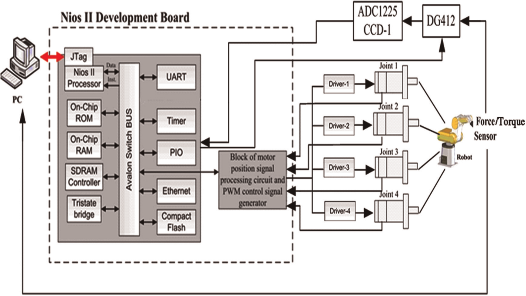
System-on-a-programmable-chip (SOPC) robotic control system structure.
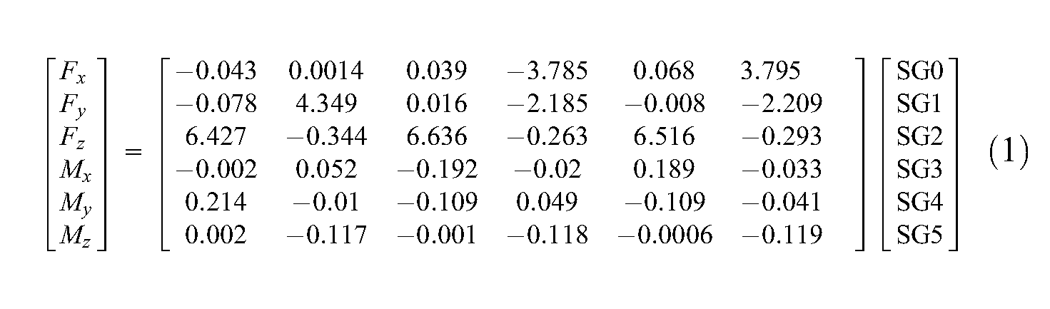
The torque-force sensor used in this study is a six-axis force sensor FT8159 from ATI with measuring ranges F z =100 N, F x =F y =32 N and T x =T y =T z =2.5 N-m. It is installed in the end-effector of a Mitsubishi robot. Its measuring signals are passed through an amplifier and then separated into two channels, to send to a sensor accompanied A/D converter for the PC PCI interface to read it and to send back to the FPGA chip for closed-loop force control purposes, respectively. This sensor output includes six sets of analogue voltage signals, SG0∼SG5, generated from six individual pressure strain gauges. They should be converted into digital signal before sent back to FPGA chip by an A/D IC. Then, the force/moment components can be calculated by using the following matrix equation in FPGA. The overall conversion frequency is chosen as 20 Hz.
Robot inverse kinematics and relationship between joint motors output torque and end-effector contact force/moment
In order to achieve the manipulator positioning and trajectory tracking control in the workspace, the kinematics, inverse kinematics and trajectory planning should be investigated. Generally, the end-effector working position or motion path in Cartesian space are converted into control variables in joint space co-ordinates for controlling purposes by using the inverse kinematics and Denavit–Hartenberg (D-H) transformation matrix. Although some efficient analysis methods have been proposed (Kazerounian, 1987; Wang and Chen, 1991), they are time consuming and need complicated mathematical operations. Since most of the assembly or pick-and-place operations are planned on a horizontal plane of the working space, the end-effector orientation is specified as orthogonal and point-down to the X–Y horizontal plane. Then the D-H transformation matrix of the end-effector with respect to the reference inertia co-ordinate is defined as
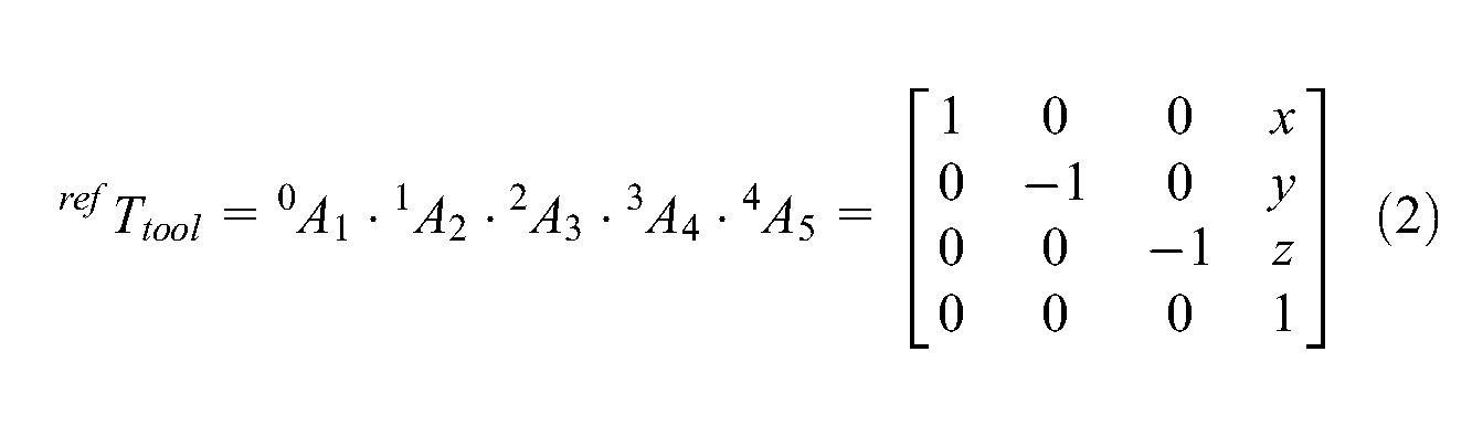
Based on the Mitsubishi Movemaster RV-M2 robot link parameters (Table 1) and forward kinematics calculation, the D-H transformation matrix can be derived and described by using the robotic D-H parameters
Denavit–Hartenberg (D-H) parameters of Mitsumishi RVM2 robot
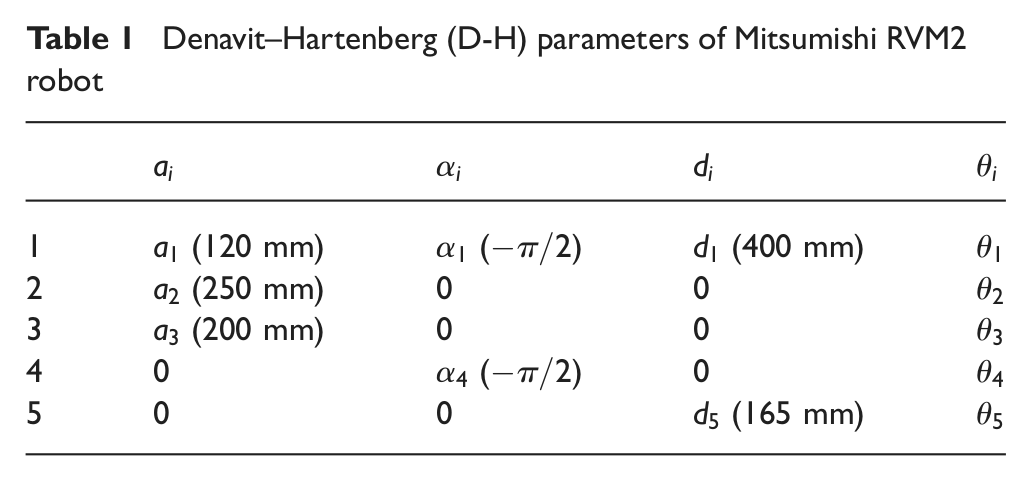

This approach can reduce the trigonometric functions calculation from 17 number of times to seven compared with that of traditional inverse kinematics. The computer time on the Nios II SOPC can be reduced from 4.5 ms to 2.5 ms to increase the system closed-loop frequency.
For this specified point-down posture as Figure 2, the joint 5 is fixed without rotation for pick-and-place purposes. Then the relationship between the joint’s angular speed and the end-effector Cartesian space rotation speed and velocity components can be derived as a 6×4 matrix.
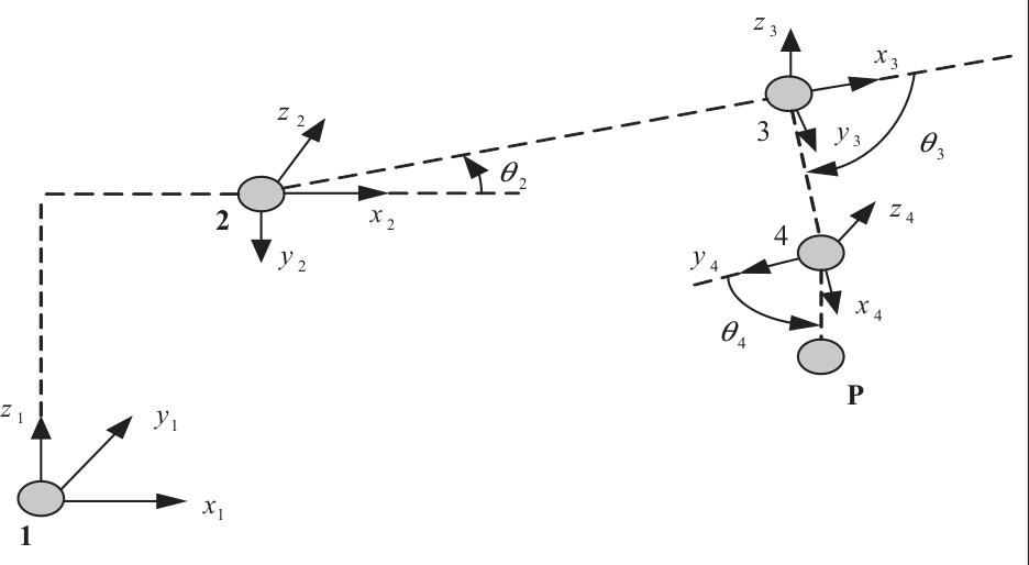
Robotic joint co-ordinate and end-effector posture.
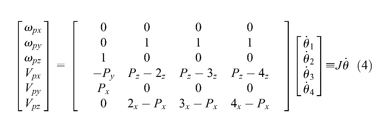
where
If the system does not have energy loss, the robot joint motors total output work should be equal to the work of end-effector actuating on the external environment based on the principle of energy conservation. Then the output torque of each joint can be derived as.
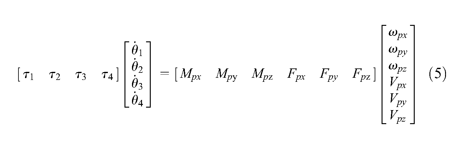
where
Substituting Equation (4) into Equation (5), we obtain

Taking the matrix transpose operation, we obtain
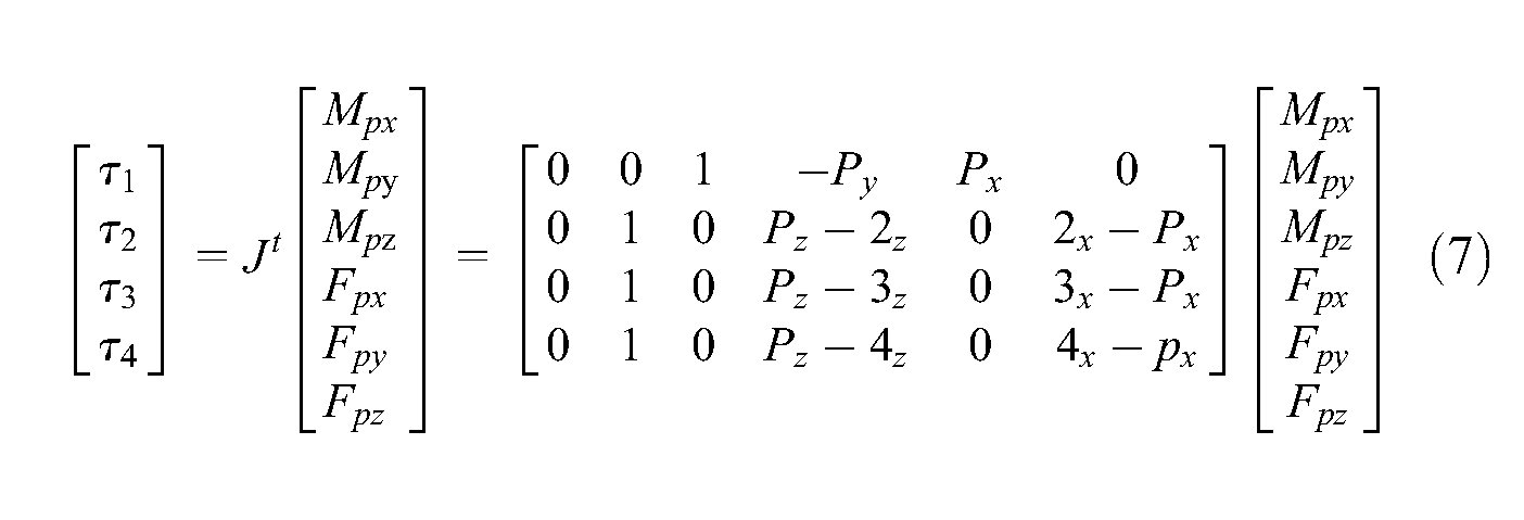
This relationship can be used to execute the hybrid impedance control for regulating end-effector compliance.
Adaptive fuzzy sliding mode controller
Since a multi-degree of freedom robotic position/force hybrid control system has non-linear and complicated dynamics behaviour, it is difficult to establish an appropriate dynamic model for the model-based controller design, especially for the onboard microprocessor. Here the sliding mode concept (Edwards and Spurgeon, 1998) is combined with fuzzy control strategy to design an adaptive model-free fuzzy sliding mode controller (AFSMC) for robotic motion control. In addition, the fuzzy variable gains scheduling strategy is integrated into the model-free fuzzy sliding mode control scheme to improve the transient response and steady-state error performance. Theoretically, it will gradually approach the control objective, the origin of a phase plane. The fuzzy sliding mode control block diagram with fuzzy variable gain scheduling scheme is shown in Figure 3. It is an enhanced and extended development from the original FSMC approach proposed (Huang and Lin, 2003) to improve the overall control performance. The basic design process of AFSMC controller is briefly described in the following steps.
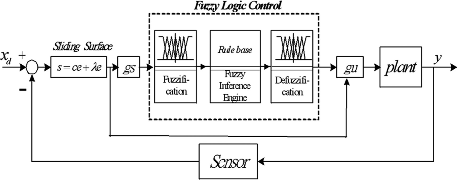
Adaptive fuzzy sliding mode control block diagram.
A sliding surface on the phase plane is defined as
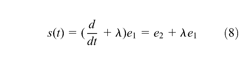
where

Since
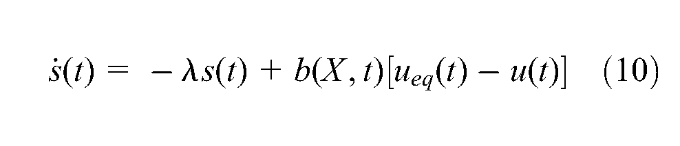
Generally,

Based on the Lyapunov theorem, the sliding surface reaching condition is
Here, a fuzzy logic control is employed to approximate the non-linear function mapping of equivalent control law,
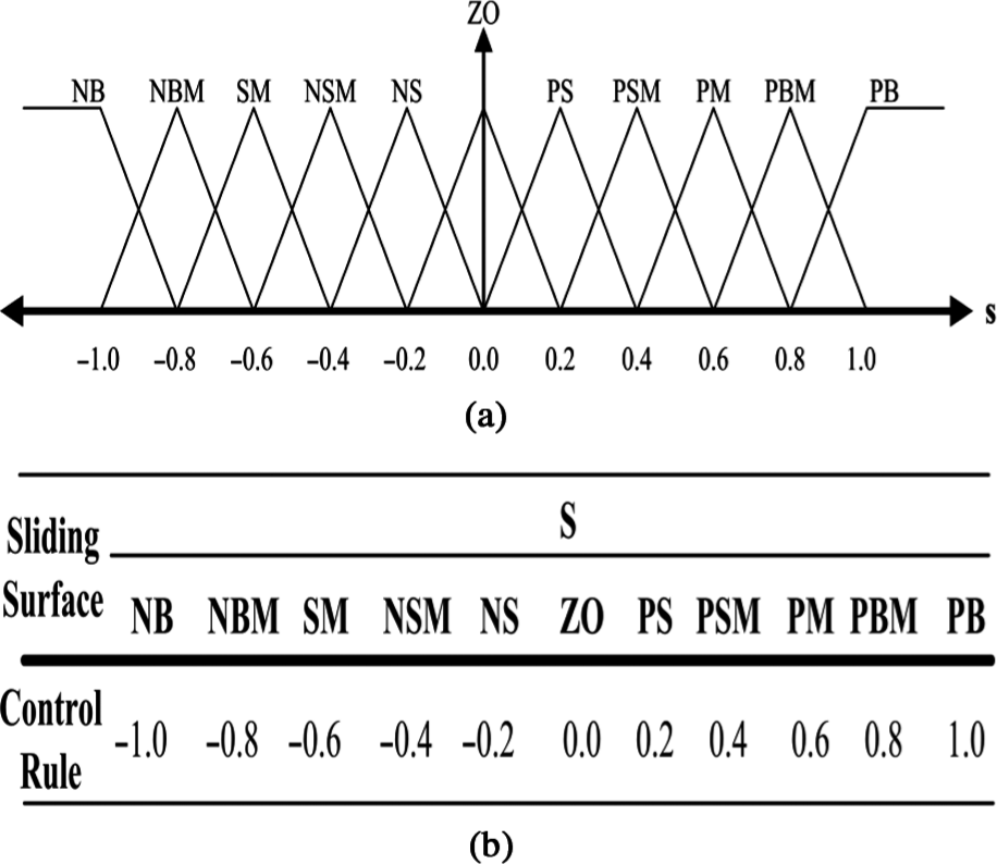
(a) Sliding variables fuzzy membership functions and (b) joints fuzzy control parameters and fuzzy control rules.
Here, 11 fuzzy rules are employed in this control system to obtain appropriate dynamic response and control accuracy. The input membership functions are scaled into the range of −1 and +1 with equal span. Hence a scaling factor
The membership function used for the fuzzification is of a triangular type. The function can be expressed as
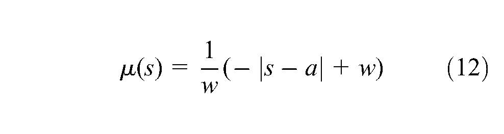
where
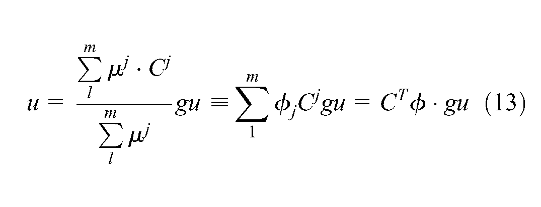
where m is the rules number,
The divisions of this membership functions can be expanded or shrunk by changing the scaling parameter of membership functions. The gain scheduling parameter is used to map the corresponding variables into this nominal range. In human beings’ intuition, when the joint angular error is large, the control voltage will be increased to provide more energy to drive the servo motor and reduce the angular error. On the other hand, when the error approaches the zero subset of membership functions, the controller should provide fine-tuning to correct the little change of angular error and reduce the overshoot tendency. These two conditions can be traded off, by scaling the divided spans of membership functions with a parameter.
A novel online parameter tuning algorithm is proposed to adjust the consequent parameter for monitoring the system control performance. The adaptive rule is derived from the steep descent rule to minimize the value of
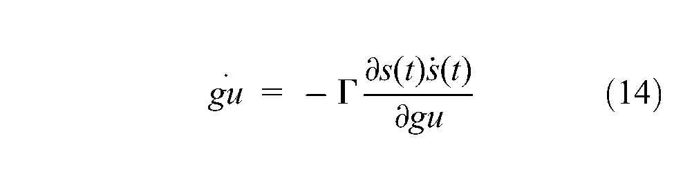
Based on the chain rule, the above equation can be rewritten as
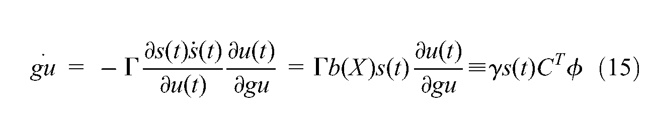
where the adaptive rate parameter,
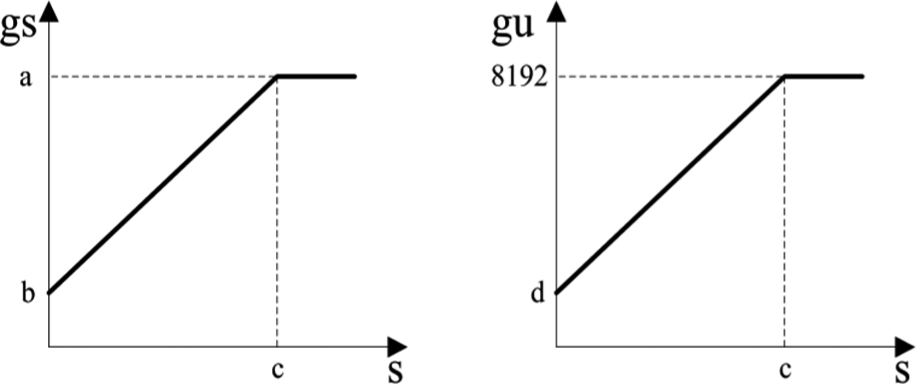
Gain scheduling parameters variation of adaptive model-free fuzzy sliding mode controller (AFSMC) position controller.
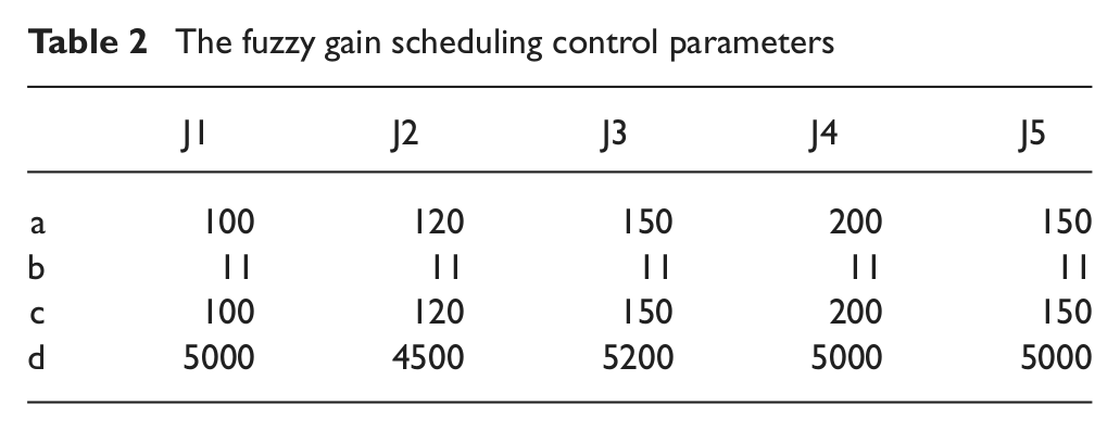
The fuzzy gain scheduling control parameters
When a robot is moving in an unconstrained working space or holding at a specified position, each joint motor of this robot needs to provide certain torque to sustain the weight of robot arm and execute the specified acceleration or deceleration operation. This sustaining component should be considered and added into the controller during force or impedance control of the robotic end-effector. These sustaining components can be obtained from the position controller. In this study, the desired end-effector contact force or impedance value is achieved by integrating the free space position control loop with an extra force control law. Since the multi-axis robotic model and system parameters are difficult to estimate, the model-free intelligent control strategy is employed. Here, the AFSMC is proposed to design each joint individual position controller and force controller based on the motor encoder position output and force sensor output installed in the robot end-effector, respectively. Then their corresponding control laws are added together to work as the driving voltage of each joint motor. The overall system control block diagram is shown in Figure 6. The AFSMC input variable membership function for force control loop is the same as Figure 4(b). The output gain scheduling parameter
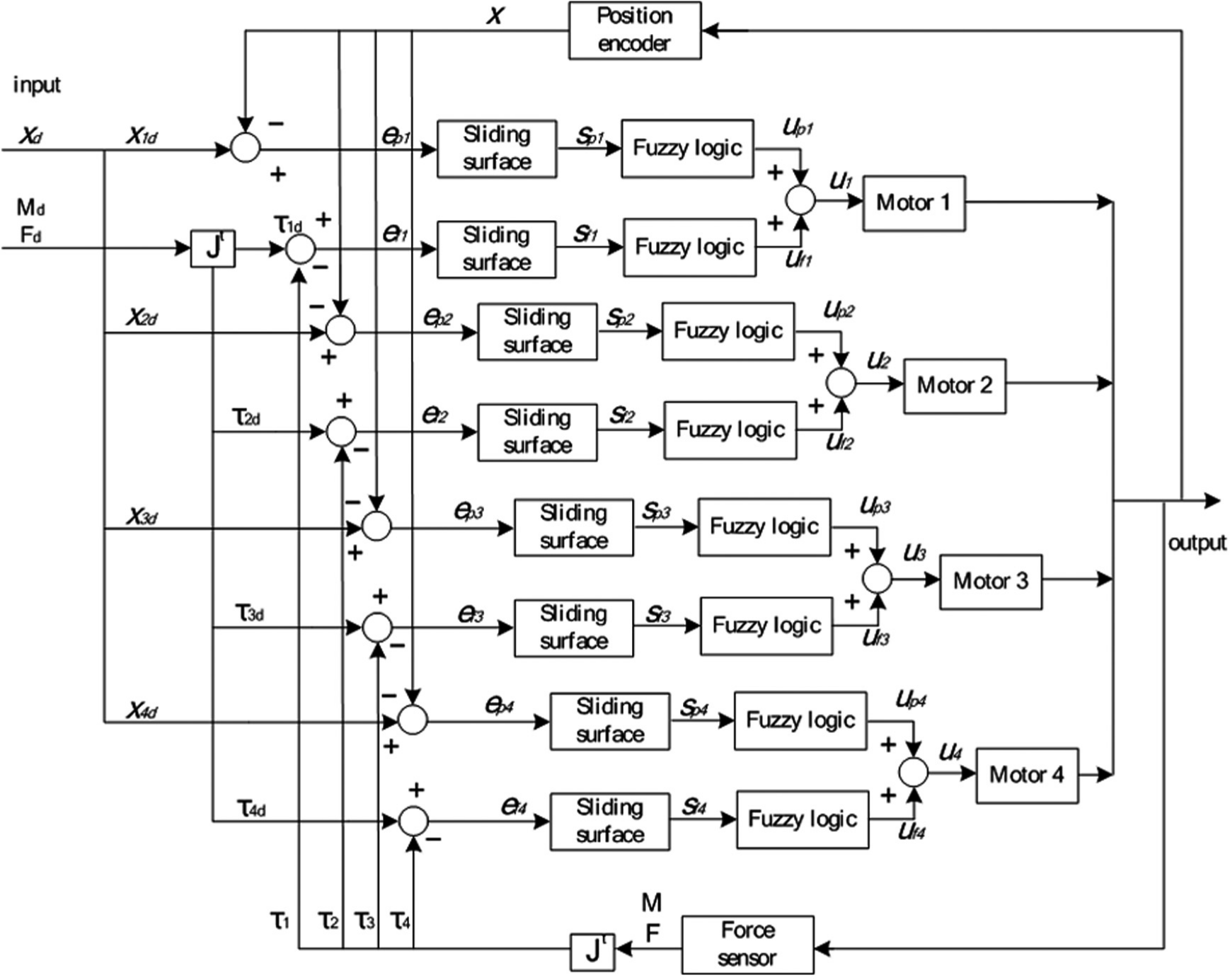
Position and force hybrid impedance control system block diagram.

Stability analysis
Lyapunov stability analysis is the most popular approach to prove and evaluate the stable convergence property of non-linear controllers, e.g. sliding mode control, fuzzy control systems. Here, Lyapunov analysis is employed to investigate the stability property of the proposed AFSMC controller. Theoretically, the fuzzy system can be used to model and approximate any non-linear function with reasonable accuracy. A basic assumption can be made for the following stability analysis.
Assumption
The optimal gain scheduling parameter
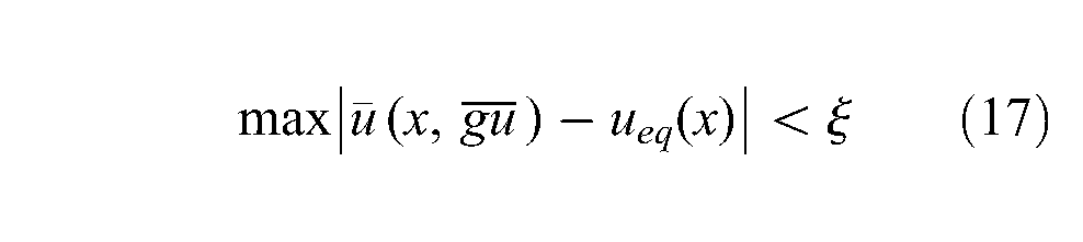
where
Define
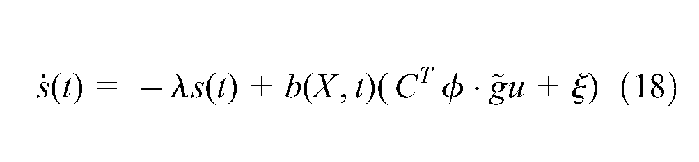
Choose the Lyapunov function as

where
Then the variation of this Lyapunov function with respect to time is
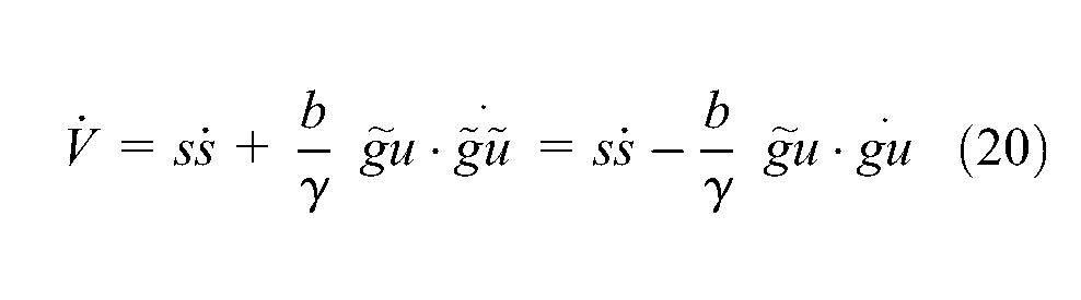
Substitute Equations (15) and (18) into the above equation, we can obtain

Then the following form can be derived.

If the appropriate parameters value are chosen to obtain
Experimental results
In order to achieve the desired motion specification and end-effector impedance in the constraint environment, the trajectory planning in Cartesian space is required for the robotic motion control. An appropriate position/force hybrid control strategy needs be designed to monitor the end-effector impedance characteristics. Here, the multi-axis manipulator is planned to execute certain contact force control at specified positions or tracking a specified contact force trajectory along a constraint surface path. A model-free 1D adaptive fuzzy sliding mode impedance controller is designed for each robotic joint with a gain scheduling scheme to control this Mitsubishi RV-M2 5-DOF robotic system. In order to investigate the transient and steady-state contact force dynamic responses of end-effector contact with environment, the following experiments were performed. The sampling frequency in these experiments was set as 20 Hz. Since the sliding variable
Contact force control at a specified position
The robot is moved to a specified position and slowly brought the end-effector normally contact with a horizontal plane before switched into force control experiment. The desired contact force is specified as 10 N–35 N–20 N with 10 s duration for each force control step. Since, the joint 2 and 3 motors contributed the major torque to the desired contact force based on robotic configuration structure, the angular errors and control torque errors of these two joints are plotted in Figure 7 as an explanation. The normal contact force in the z direction and the control voltages of joints 2 and 3 are shown in Figure 8. The coarse line (black) is represented the force control law and the thin line (blue) is depicted the position control law. The negative force value means the pushing contact force and the negative control voltage is used to lift up the robot links. The force control error is kept within 2 N for 10 N and 20 N duration. The joint angular error is less than 0.15° due to robotic mechanism compliance.
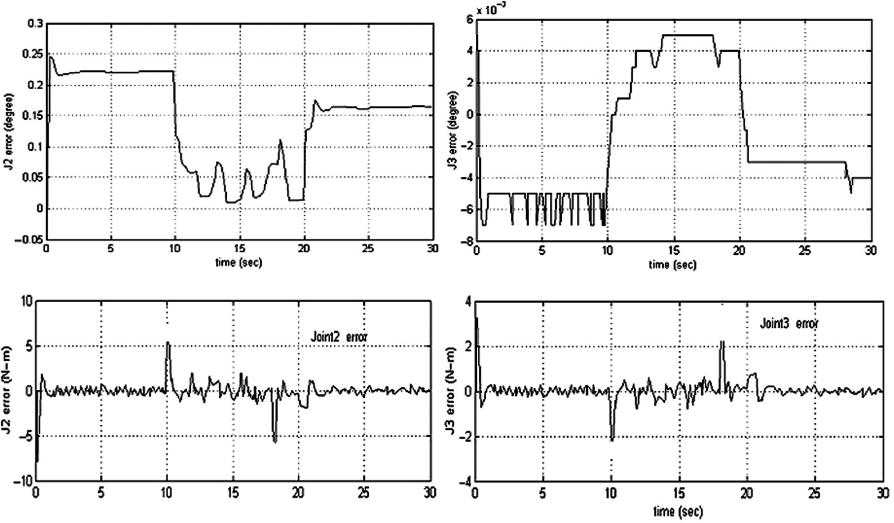
The angular errors and control torque errors of joints 2 and 3.
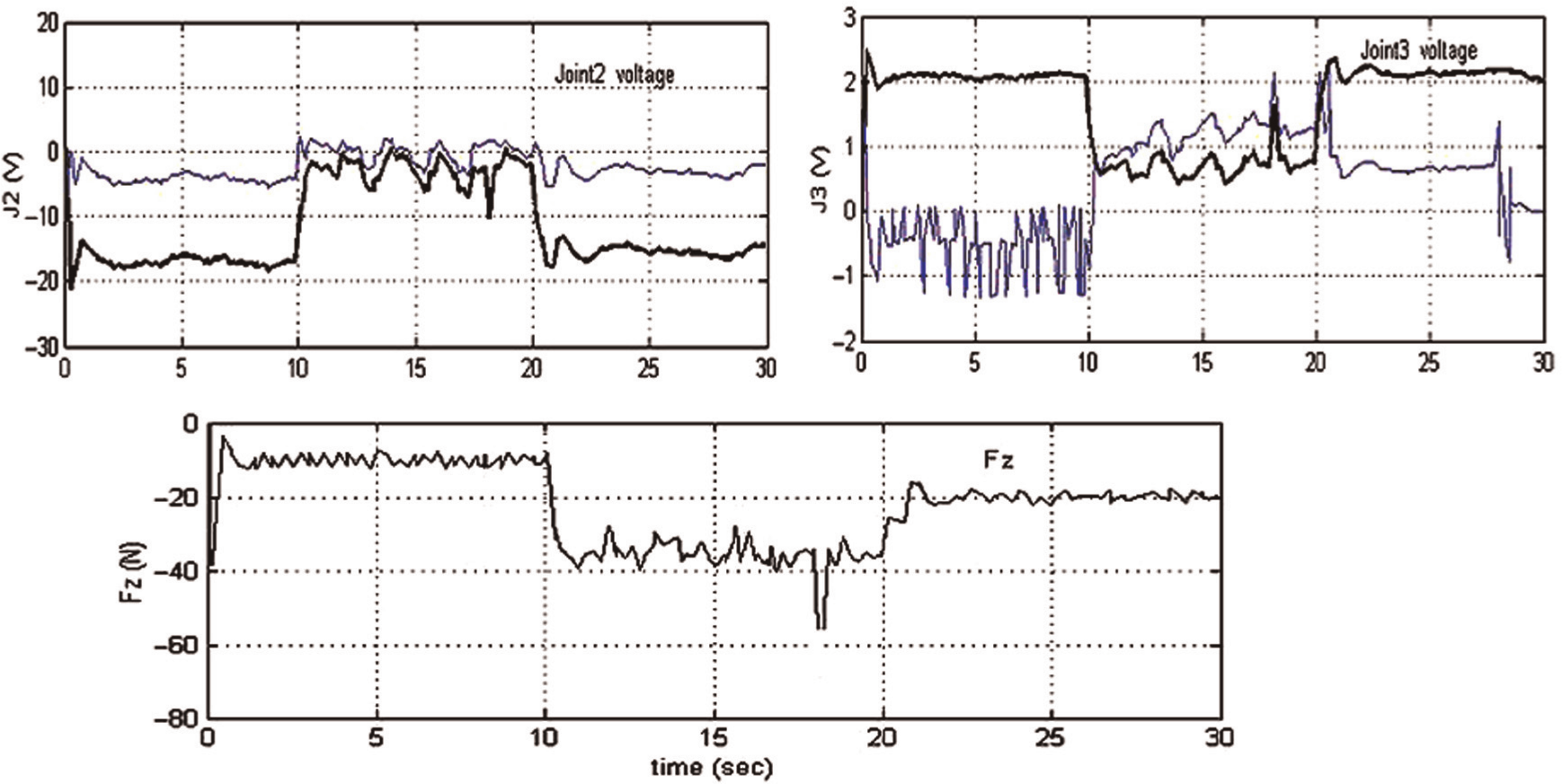
The normal contacted force in the z direction and the control voltage of joints 2 and 3 (coarse line – force control; thin line – position control).
The end-effector is sliding in a plane and the contact force has step changes
In the beginning, the robot end-effector is brought to contact with a horizontal plane X–Y. The end-effector is planned to move in the Y-axis with 0.2 cm/s constant speed and the normal contact force is changed step by step 30 N–10 N–20 N with 10 s duration for each step. The angular errors and control torque errors loci of joints 2 and 3 and the contact force duration locus are shown in Figure 9. The joint angular error is less than 0.35° and the force control error is less than 5 N.
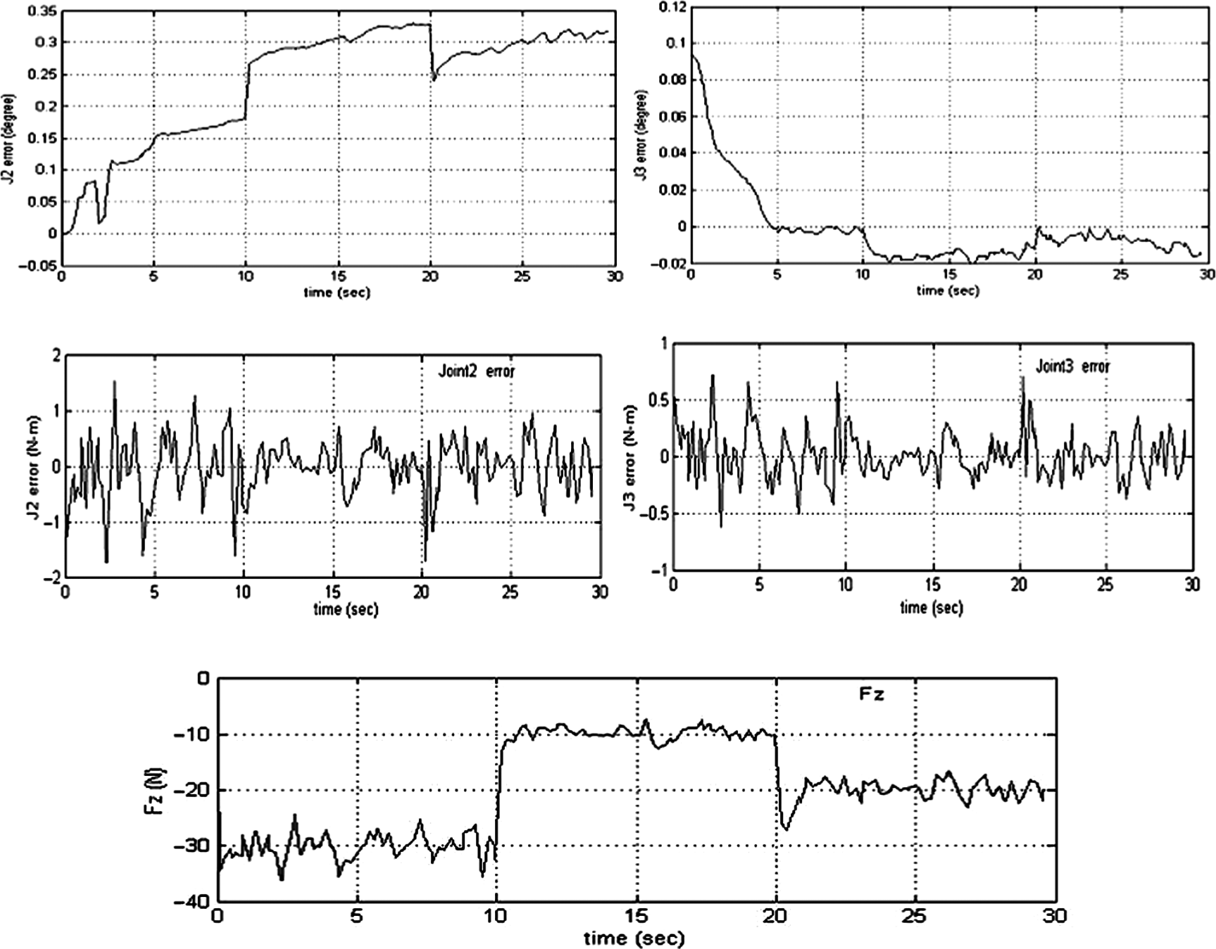
The angular errors and control torque errors history of joints 2and 3 and the contacted force history in the Z-axis.
From free space position control switch into hybrid control structure
In order to evaluate the robustness of the proposed hybrid controller, the robot end-effector in this experiment is planned to move from free space into a constraint horizontal surface with 40 N contact force requirement. The end-effector is slowly moving down with 0.1 cm/s velocity along the Z-axis in position control mode. When the detected contact force of force sensor reaches 10 N, the control system is automatically switched into hybrid control mode and the end-effector motion direction is changed from the Z-axis into the Y-axis with 0.2 cm/s constant velocity. The angular error trajectory of each joint is plotted in Figure 10. The control voltage and joint torque controlled error of joints 2 and 3, and the normal contact force in the Z direction are shown in Figure 11. It can be observed that the joint angular is less than 0.25°, the joint torque error is less than 2 N-m and the force error is less than 5 N.
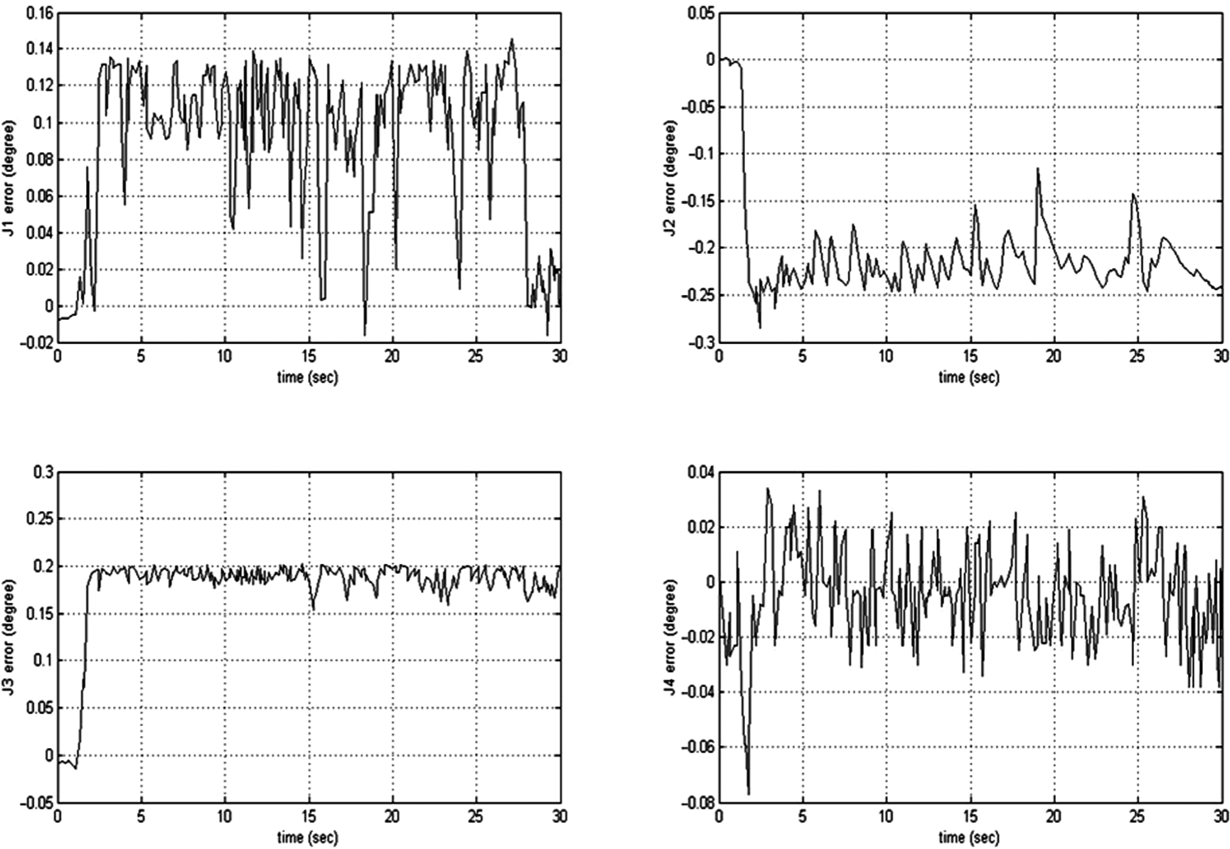
The angular error history of each joint.
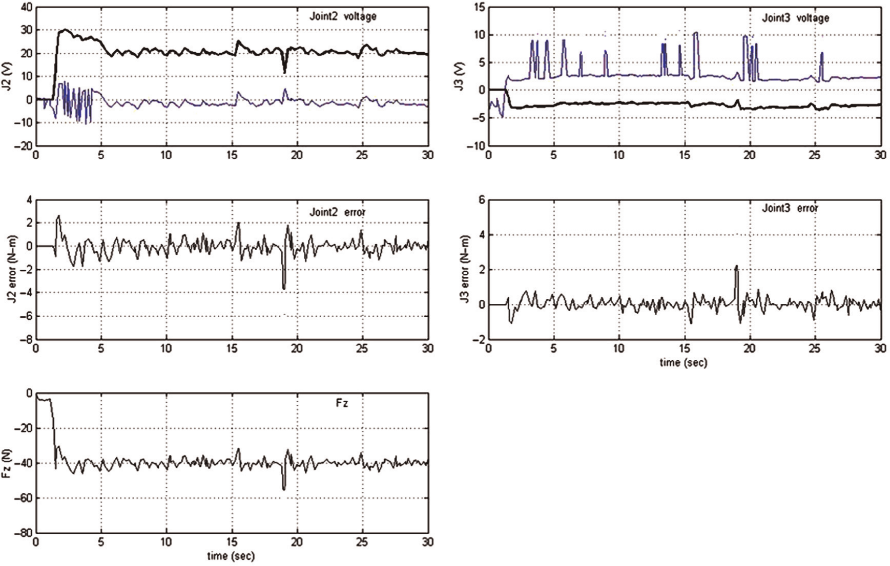
The control voltage and joint torque controlled error of joints 2 and 3 and the normal contacted force in the Z direction, respectively.
End-effector moving in a 3D irregular slope with a specified constant contact force
In the beginning, the robot is not in contact with a constraint environment. The end-effector is slowly moving down with 0.1 cm/s velocity along the Z-axis in position control mode. When the detected contact force of force sensor reaches 10 N, the control system is automatically switched to hybrid control mode. The end-effector is specified to follow the 3D constraint surface motion with 0.4 cm/s constant velocity along the Y-axis and the constant contact force with the constraint surface is set as 25 N. Then the proposed hybrid impedance control strategy is employed to execute the 3D Cartesian space position control and the Z-axis contact force control simultaneously. The 3D constraint surface and the angular error locus of each joint are plotted in Figure 12. The joint angular error is less than 0.05°, except for joint 4, which is chattering within 0.2° due to this joint motor working on a clockwise and anticlockwise switching situation. The angular error high-frequency variation is due to the sliding motion on the irregular contacted surface and position control mode with high gain for accurate contour tracking requirement. The joint controlled torque error of joints 2 and 3 and the normal contact force in the Z direction are shown in Figure 13. The joint controlled torque error is variation within ±1 N-m and the force control error is less than 3 N. The end-effector 3D motion trajectory and the contouring error are shown in Figures 14(a) and (b), respectively. The contouring error is less than 1.1 mm. It is good enough for most of the assembly applications.
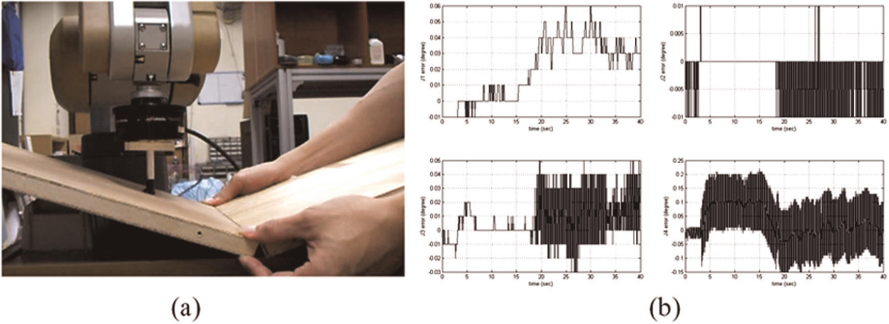
(a)The 3D constraint surface and (b) the angular error of each joint.
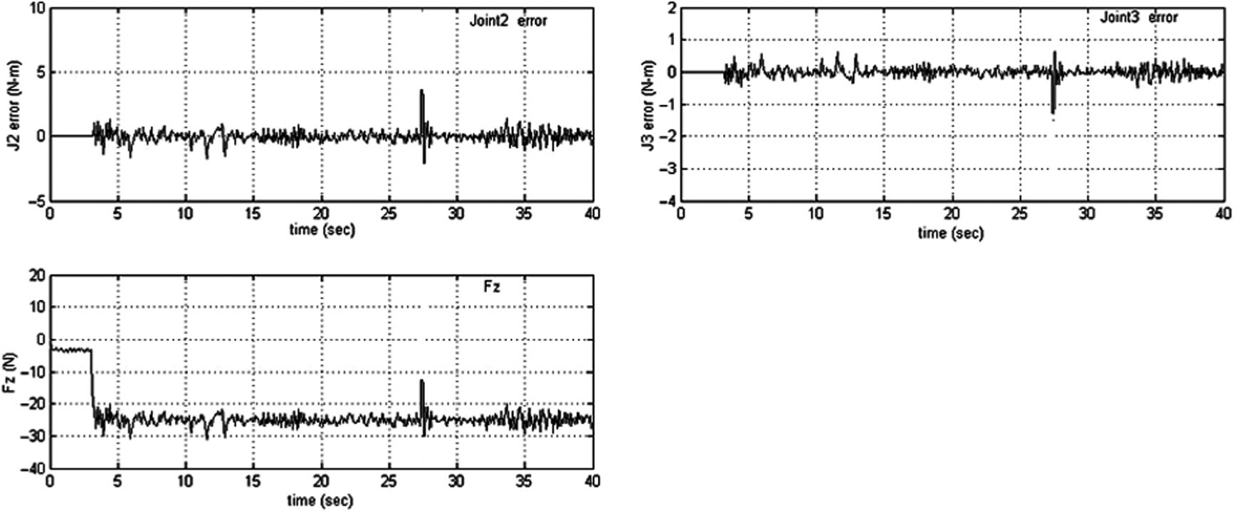
The joint controlled torque error of joints 2 and 3 and the normal contacted force in the Z direction.
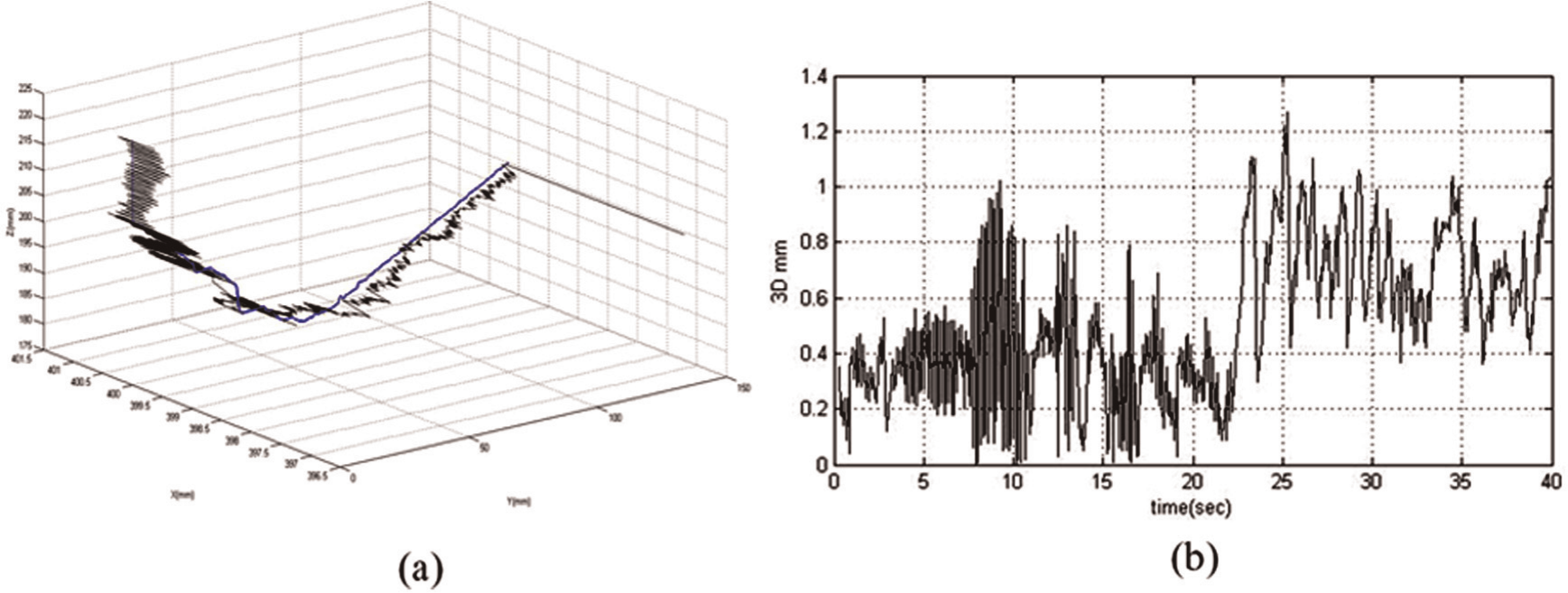
(a) The end-effector 3D motion trajectory and (b) the contouring error.
Conclusion
An FPGA-embedded control structure is implemented on a retrofitted Mitsubishi 5-DOF robot for position/force hybrid control. An adaptive model-free fuzzy sliding mode controller was designed for each joint to execute intelligent hybrid impedance control. This control strategy has model-free and adaptive gain scheduling advantages for achieving good transient and steady-state responses. The 1D AFSMC controller has a simple strategy and is easy to design and implement. It can reduce the computing time and database for onboard system consideration. In addition, its online adaption can improve the transient and steady-state control performance and system stability properties. The experimental results show that this AFSMC hybrid intelligent control system can effectively monitor the specified robotic end-effector motion trajectory and the contacted force with constraint surface simultaneously in Cartesian space. This intelligent embedded control structure can be employed in pick-and-place, assembly and simple interactive operations
Footnotes
Funding
This research received no specific grant from any funding agency in the public, commercial, or not-for-profit sectors.