This paper considers the problem of time-varying force control for robot manipulators in the presence of uncertainties from both the robotic model and working environment. The position-based impedance control (PBIC) method is employed and in order to achieve accurate time-varying force tracking, an improved PBIC is proposed. A neural-network-based robust controller is proposed to compensate for the system uncertainties, and an adaptive law is developed to identify the uncertain environmental parameters. Simulation results on a two-link robot manipulator confirm the effectiveness of the method in achieving time-varying force tracking.
Robotic systems are often required to physically interact with their working environments, and the regulation of the interaction force is of vital importance during a safe and stable operation. During these applications, the interaction force to be controlled is often assumed to be a constant value, such as with deburring, grinding, welding, etc. Recent robot-assisted applications require the control of a time-varying interaction force, a typical example of which is in robot-aided cell injection where a time-varying injection force is needed due to the elastic properties of the cell membrane (Huang et al., 2008; Xie et al., 2010). Similar applications can be found in stroke rehabilitation where the robot manipulator is designed to impede the patients’ movements, and the patients are guided to repeatedly overcome a series of specified time-varying resistive forces so that their muscle power can be restored gradually (Freeman et al., 2012; Krebs et al., 2012; Varkuti et al., 2013). In these newly emerging applications, robot manipulators are expected to perform direct time-varying force tracking, thus, time-varying force-control schemes are required.
The most widely applied robot force-control method is impedance control (Hogan, 1985) which proposes to indirectly achieve force regulation via position control with little modification to the already existing robotic servomechanism. According to the way the torque of the actuator is derived, two frameworks of traditional impedance controller, namely position-based impedance control (PBIC) and torque-based impedance control (TBIC), are discussed and applied. Many control algorithms within these two frameworks have been developed with the purpose of improving the robustness of the original impedance control function, or giving direct force tracking ability to impedance control (Jung and Hsia, 2000; Lee and Lee, 1991). The TBIC, a complete dynamic-model-based method, is difficult to implement on industrial robots because of its sensitivity to model uncertainties (Bigras et al., 2012). Alternatively, the PBIC that is composed of an inner-loop position controller and an outer force-control loop makes it an attractive approach for typical industrial manipulators, as they are often designed as accurate positioning devices (Lawrence, 1988).
To date, the interaction force between the end-effector and the environment is still supposed to be a fixed value, and the force control algorithms in robot manipulators are mostly concentrating on a constant reference-force tracking (Amir and Akbar, 2000; Bigras et al., 2012; Goldenberg, 1988; Raibert and Craig, 1981; Seraji and Colbaugh, 1997; Seul et al., 2004; Zeng and Hemami, 1997). Preliminary work on time-varying force control in robotic manipulator systems can be found in Seraji (1994), where a cosine function reference force is tracked in the simulation study. Recently, an automatic cell injection system was developed and the time-varying force trajectory was tracked (Huang et al., 2012; Xie et al., 2008, 2010) by using an improved PBIC (IPBIC) method. The improved method serves as a promising indirect force controller as it not only offers more degrees of freedom to regulate the robotic mechanical dynamics, but also endows the PBIC method with the ability to track diverse force trajectories. In order to fully exploit the potential of this improvement and also to extend its applicability, it is necessary to further investigate its essence and to demonstrate its effectiveness in practical implementations.
This paper presents a deep discussion of the IPBIC, and gives the first results about its essence in tracking time-varying reference force. Further, to compensate for the model uncertainties, a neural network (NN)-based position controller is first designed. NNs utilized for robot position control (Jung and Hsia, 1998, 2000) has been widely reported, without, however, the consideration of both model and environment uncertainties. The stability analysis of the robust NN-based force control method is rigorously presented. To identify the uncertain environment information, an adaptive law deriving from the Lyapunov-based stability analysis is proposed. A major contribution of this paper is the development of a time-varying force control scheme in the presence of both model uncertainties and environmental uncertainties, and also the essential investigation of the proposed IPBIC.
The paper begins in the next section with a review of the traditional PBIC, and its limitation in achieving accurate force tracking is referred to. In order to realize time-varying force control, the IPBIC is proposed in Section 3. Section 4 gives the planned position trajectory for the position controller which indirectly realizes the tracking of the time-varying reference force signal. In Section 5, a robust feedforward NN position controller is designed, and the stability analysis is rigorously presented. An adaptive law used for environmental identification is developed in Section 6. A comparative simulation study demonstrating the robust force control scheme is given in Section 7. Finally, conclusions are briefly stated in Section 8.
Traditional PBIC
As a well-known inner/outer approach to interaction force control, the PBIC, established upon the existing industrial robotic position controllers, serves as a novel force control strategy. One may summarize PBIC, according to Valency and Zacksenhouse (2003) and Chiaverini et al. (2002), as follows: a dynamic relationship between force and position is derived, and once the interaction force is sensed in the outer loop, it will be transformed into the corresponding position signal via an impedance function and then controlled by the inner position controller.
Given a rather accurate measured interaction force and a well structured environmental model, the accuracy of force tracking is mostly dependent on the performance of the inner position controller. As a result, accurate modelling of the manipulator and the environment systems, and a high-accuracy position controller, are all preliminaries to satisfactory force tracking.
The traditional impedance function (Jung and Hsia, 1998) utilized takes the form
where , and are diagonal symmetric positive-definite matrices of desired inertia, damping and stiffness gains, respectively. is the reference input trajectory for the inner position-controlled system, and is the actual end-effector position in Cartesian space. It has been pointed out that the traditional impedance function only specifies compliant behaviour of the manipulator and lacks the force-tracking ability because the reference force signal is not involved.
A modified target impedance function which claims to endow the impedance controller (1) with the direct force tracking ability via the introduction of the reference force signal (Goldenberg, 1988) is introduced:
where is the reference force trajectory. In the free space where there is no contact between the end-effector and the environment, we have , and the outer loop disappears and the overall system is a pure servomechanism. When the manipulator contacts the environment, a dynamic relationship between the end-effector position and the interaction force is specified by (2), and the force control problem is again transformed into a position control problem. If a ‘perfect’ position controller is assumed, namely , then we have .
Rewrite (2) into the form
where denotes the position deviation and is the force control error. It is shown that (3) achieves force control by limiting both position error and force error to within acceptable ranges. Therefore, neither accurate position control nor accurate force control can be achieved because only a compromise between and is achieved.
Without loss of generality, in the subsequent analysis we consider each Cartesian variable separately and replace the upper-case vectors , , , and matrices , , in (1) with the lower-case scalars , , , and , , . It has been reported in much of the literature that if time-invariant force tracking is required, zero steady-state force error can be achieved when the following equation holds (Amir and Akbar, 2000; Seraji and Colbaugh, 1997):
Thus, for the problem of time-invariant force control, the planned trajectory used to realize the tracking of is the function of , and . In other words, if the environment location and the environment stiffness are known a priori, the reference position can be accurately synthesized from (4).
However, the above presentation is developed based on three assumptions: 1) the reference force to be tracked is defined as a constant, which limits its usage in applications requiring time-varying force regulation (Freeman et al., 2012; Huang et al., 2008; Xie et al., 2010); 2) a ‘perfect’ inner position controller is assumed (), which is practically impossible because of the unmodelled robot dynamics; 3) the environment information is known a priori, however, in most of the robotic applications (Amir and Akbar, 2000; Goldenberg, 1988; Raibert and Craig, 1981; Seraji and Colbaugh, 1997; Seul et al., 2004; Zeng and Hemami, 1997), the environment position and the environment stiffness are usually uncertain or time-dependent.
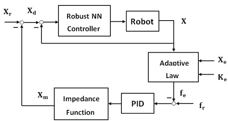
Therefore, time-varying force tracking capability of the robot manipulator is required, in which the robot is also expected to show robustness to the unmodelled dynamics and to identify the environmental information. The resulting control scheme of the manipulator–environment system in this paper is shown in Figure 1, where is the planned trajectory for the position controller, which is derived from trajectory planning, and is the output the improved impedance function, followed by the introduced proportional-integral-differential (PID) force compensator. The inner position controller is a NN control scheme to be developed, and the adaptive law is used to identify the environmental information, . All the joint variables of the manipulator are observed with a Kalman observer.
Robust NN-based IPBIC control scheme.
IPBIC
As has been pointed out, in the framework of PBIC, the force tracking performance is largely dependent on the position trajectory tracking capability of the manipulator system. An obvious way to improve force tracking is to apply high-gain position controllers. Although high-gain position controllers are able to speed up the closed-loop response and enhance tracking performance, increasing the gain has an unnecessarily adverse effect on the robust term whose amplitude will increase accordingly (Bascetta and Rocco, 2010; Sciavicco and Siciliano, 2000; Spong et al., 2008). Alternatively, based on the idea of cascade control where an additional controller is introduced when the main variable is of poor tracking, a natural and direct way is to add the other controller so that an inner–outer control framework is formed. In the framework of impedance control, reducing the force tracking error seems to be a natural method to facilitate both position and force control.
Therefore, in order to obtain accurate force tracking, and at the same time to remove the concerns over the high gains of the position controller, a modification of force error has been made in terms of the introduction of a PID compensator:
The main controlled variable of the manipulator in contact space is the interaction force, and the most immediate effect of the PID controller is a more rapid force tracking response, greater force tracking ability and further reduction of the force tracking error. The PID force compensator works in combination with the inner position controller and makes the realization of time-varying force tracking more flexible, more rapid and more accurate.
It has been pointed out that for time-invariant reference forces, the reference trajectory is calculated based on the desired force , the environment position and the environment stiffness (Jung and Hsia, 2000; Seraji and Colbaugh, 1997), as given in (4). Given the fact that the proposed IPBIC still falls into the indirect force control method, time-varying reference force tracking with IPBIC is indirectly achieved by the inner position controller. Therefore, a reference position trajectory for the inner servomechanism should first be specified. The next section gives the planned position trajectory of this improved impedance control, and also the essence of this improvement in performing accurate force tracking.
Trajectory planning of time-varying reference force
Using the following linear spring system to approximate the environment model has been a widely adopted method by many researchers:
where is the environment stiffness and is the location of the environment at ease. It is usually assumed that is the point at which the manipulator environment interaction force is zero.
Then, based on (6), the actual location can be expressed as
Substituting (7) and its first- and second-order derivatives into the improved target impedance model (5) yields the force-error differential equation
By applying the Laplace transformation, we have the steady-state force error in the form
Obviously, if and only if the numerator of (9) equals zero, namely
holds, the steady-state force error converges to zero.
Thus, the newly planned trajectory of the end-effector is derived as
It is obvious that the newly planned trajectory is a dynamic function of the environment , the reference force and the impedance parameters , , . If it is assumed that the environmental information is known a priori and the impedance parameters are suitably chosen, the new position trajectory will change with , thus removing the constraint condition of being a fixed value in (7).
Computing the force tracking error of the original impedance function (2) and comparing it with the newly obtained error (9) yields
where is the steady-state force tracking error of the traditional impedance function. It is observed that the steady-state force tracking error of the improved impedance function is further reduced by the fact that the force controller gains and merely affect the dominator of the force tracking error in (15). Therefore, the newly derived force tracking error will be successively reduced when the PID controller gains are continually increased. This is the essence of the IPBIC in performing accurate force tracking. Further, the inner–outer loop controller supplies more actuation torque than a single-loop feedback controller, and this also contributes to the tracking of the time-varying reference force.
Robust NN-based position controller
Once the planned trajectory is obtained, a position controller should be designed so as to accurately track , and, further, an adaptive algorithm is needed to obtain exact values of and required in (13). It is clear that no matter whether there is an interaction force, the inner loop always remains a position servomechanism. Therefore, a robot position controller is first designed in the following section, that starts with the analysis of the modelling uncertainties, and then proceeds to the design of the NN-based robust control scheme.
According to the Euler–Lagrange equation of motion, an -joint manipulator can be described as
where is the symmetric positive-definite inertia matrix, denotes the matrix containing coriolis and centrifugal forces, , are the vectors of actuator joint friction force and uncertain disturbance, is the vector of gravity and is the vector of applied joint torques. Further, is the Jacobian matrix of the manipulator and is the interaction force from the environment when there is contact between the manipulator and the environment. The robot manipulator dynamics system (16) has the following properties which can be properly utilized for the development of control algorithms (Spong et al., 2008).
Property 1. The inertia matrix is symmetric, positive definite and uniformly bounded for all , namely, the following inequalities hold:
Property 2. The matrix is skew-symmetric for any , , such that
In view of the uncertainties in the dynamic model, the NN is employed to cancel out uncertain terms, and a robust term is added to cope with the disturbance and the estimation error of the NN. The basic idea behind NN-based control is to learn unknown nonlinear dynamics and compensate for uncertainties existing in the dynamic model without any preliminary offline training (Fierro and Lewis, 1998; Lewis et al., 1999). According to the Radial Basis Function (RBF) NN function approximation property (Lewis et al., 1995, 1999), given a continuous function with variables on a compact set , there exist neurons and weight matrix so that
where denotes the NN approximation error satisfying for some . Further, and is the RBF function, where the normally used Gaussian RBF function is defined as
where and are the centre value and width of the th neuron.
Now, define the joint position tracking error to be and the error function
where . Then, the following equation is derived:
that is,
where is termed the robot uncertainty with input .
Based on the error dynamics in (23) and the subsequent stability analysis, a robust adaptive NN-based control scheme is given as
where is an estimate of robot uncertainty and is the robust term.
Substituting control law (24) into the system (23) results in the error equation
where .
In order to 1) enhance the approximation accuracy of the RBF NN, 2) make the robust term less conservative, and 3) achieve faster weight-tuning algorithms, a model block approximation NN is utilized to estimate the different parts of the robot uncertainty term.
Let and , and the uncertain term can be rewritten as
Taking the four terms in one at a time, the estimates of the four terms can be obtained with the RBF NN, namely, , , , .
Now, the functional estimation of with a feedforward RBF NN can be given as
where
and
The above results give a partitioned NN that contains four neural subnetworks. One obvious advantage of such a structured NN is that the individual NN can be tuned separately, which will facilitate the weight update procedure. Then, a simple and effective adaptive law for the weight matrix is introduced here for simplicity (Lewis et al., 1995):
where denotes any constant matrix, and design parameters , , , .
Theorem 1. If control input (24) and the adaptive law (28) are designed respectively, and the compensator is selected as
where , are the least upper bounds of the NN estimation error and the disturbance . Then, the tracking error is unknown upper bound and the NN weight estimates are bounded.
Proof: Consider the following Lyapunov function candidate:
Differentiating both sides of (30) and substituting yields
Taking into account (25), we have
Substituting the adaptive laws (28) together with yields
Taking into account the robust term (29) and considering the following property:
where , we have
where and .
Then, it is given that
In order for , the following inequality should be satisfied:
Namely,
where
It is obvious that
namely, the resulting inequality holds:
The other way to satisfy can be easily obtained via investigation of (36), that is, the following hold:
From (40), one can conclude that the smaller of the upper bounds of the weight matrix and the larger the control gains , the smaller the convergence radius of becomes. Since and , this shows the stability in the sense of Lyapunov such that both the tracking error and the weight estimate matrix error are bounded.
Adaptive law for environmental uncertainties
Modelling the interaction between the robotic end-effector and the contact environment has been an important topic in recent years (Gilardi and Sharf, 2002; Hunt and Crossley, 1975; Sun and Nelson, 2002). According to the essence of impedance control, the environment should be modelled as a second-order linear impedance function (Pelletier and Doyon, 1994), while a much simpler model has been widely adopted because the stiffness term dominates the interaction dynamics. Hence, as discussed in Section 3, the following simple and effective model is utilized to approximate the actual interaction force:
Practically, the environment position might be an uncertain value. Furthermore, for some particular manipulation circumstances where the environment is rather compliant, the environment stiffness is also uncertain. Therefore, precise identification methods should be developed to obtain accurate environment information.
We now turn to the development of the indirect adaptive method employed to estimate the environment parameters. Assuming the estimated value of the environment stiffness and position to be and respectively, we have the estimation of the sensed contact force,
where is the prediction of based on the current estimate of and , and .
Defining
and subtracting (42) from (6) yields
Thus, our goal can now be turned to the scheme for adjusting and so that as .
Supposing be well achieved, and thus , we have the following update law derived by the Lyapunov approach.
As for the system (43), we specify the positive quadratic Lyapunov function as
where denotes a positive-definite matrix. It is observed that if is specified as
then differentiating (44) along (45) yields the negative semidefinite function
Thus, according to (44) and (46), the underlying asymptotically stable conditions for the system (43) is derived.
Straight calculation of (44) yields the complete indirect adaptive time-varying force tracking schemes
where , are positive scalar constants. In order to enhance the robustness of the control algorithm, the modification terms (Seraji and Colbaugh, 1997) are added to the control laws (47) and (48), an thus, the improved adaption laws are given as
where , are small positive constants. With further investigation of (49) and (50), we can find that the values for and can not be obtained at time . Alternatively, it is reasonable to suggest using the easily-stored delayed sampling values and as alternatives where is the sampling period.
The contact force measured by the force sensor is always a noisy signal and direct differentiation of this signal to obtain will bring undesirable high-frequency noise in practical implementation. One approach is to filter the force signal to remove the high-frequency noise, and then to differentiate the filtered force signal, such as a simple dominant pole filter (Volpe and Khosla, 1993), or a second-order low-pass filter (Seraji and Colbaugh, 1997; Volpe, 1990).
Alternatively, the following approximation can be found where then,
Thus, the derivative of force error in (5) can be approximated by (51) where the position variables are obtained via a Kalman observer.
Simulation
Comprehensive simulation studies have been carried out using a two-link robot manipulator, the parameters of which are taken from a widely studied robotic model, where
The joint friction force is specified as . For the purpose of easy implementation, the parameters of the links are considered to be with initial conditions and . The simulation studies start with the identification of the environmental information, and proceed with the demonstration of the robust NN position control in the presence of bounded uncertainties. Finally, based on the adaptive law and the NN-based position controller, the time-varying force tracking is evaluated.
Identification of the environment
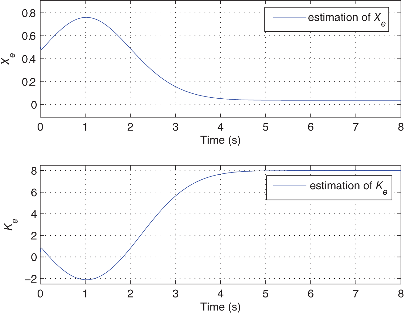
First, evaluation of the proposed adaptive algorithms in varied environment locations and environment stiffnesses is investigated. Initially, the desired environment information is set to be and with the initial environment locations , . Via trial and error, the following suitable parameters are chosen: , , .
The identification accuracies of the two environmental parameters interact with each other, as depicted in Figure 2. At the beginning of the identification, the performance in identifying and is poor for both. After around the fourth second when one of them is perfectly tracked, the other is also approaching its desired value.
Online identification of and .
Position control of robust NN-based IPBIC
Planned trajectories for the position controller are calculated from (13), where the time-varying reference force that mimics robot-aided cell injection (Huang et al., 2008; Xie et al., 2010) is utilized. To fully evaluate the tracking performance, reference force trajectories along the - and -axes are specified by and . The parameters of the impedance controller are chosen to be , and , which represents a critically damped second-order manipulator–environment system. For the NN controller, we have chosen five hidden neurons and the parameters are selected to be , , , and the parameters for the robust term are , .
In order to fully demonstrate the robustness of the robust NN-based term, comparisons are performed between the IPBIC and the NN-based IPBIC. The model uncertainties are approximated by a bounded disturbance taking the form
The disturbance is added to the system at the moment s so that the tracking performance without uncertainties and the robustness in the presence of uncertainties are fully examined.
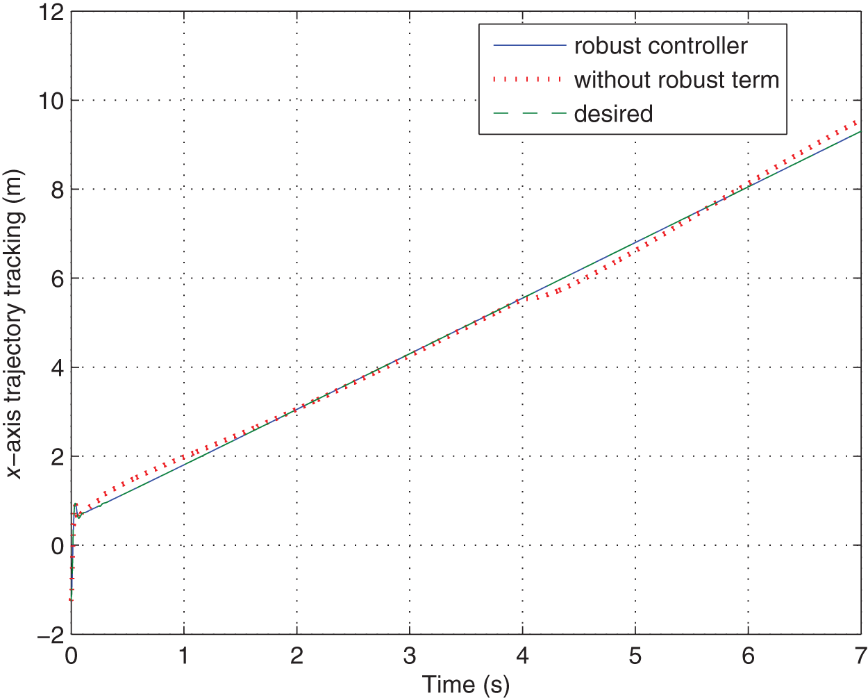
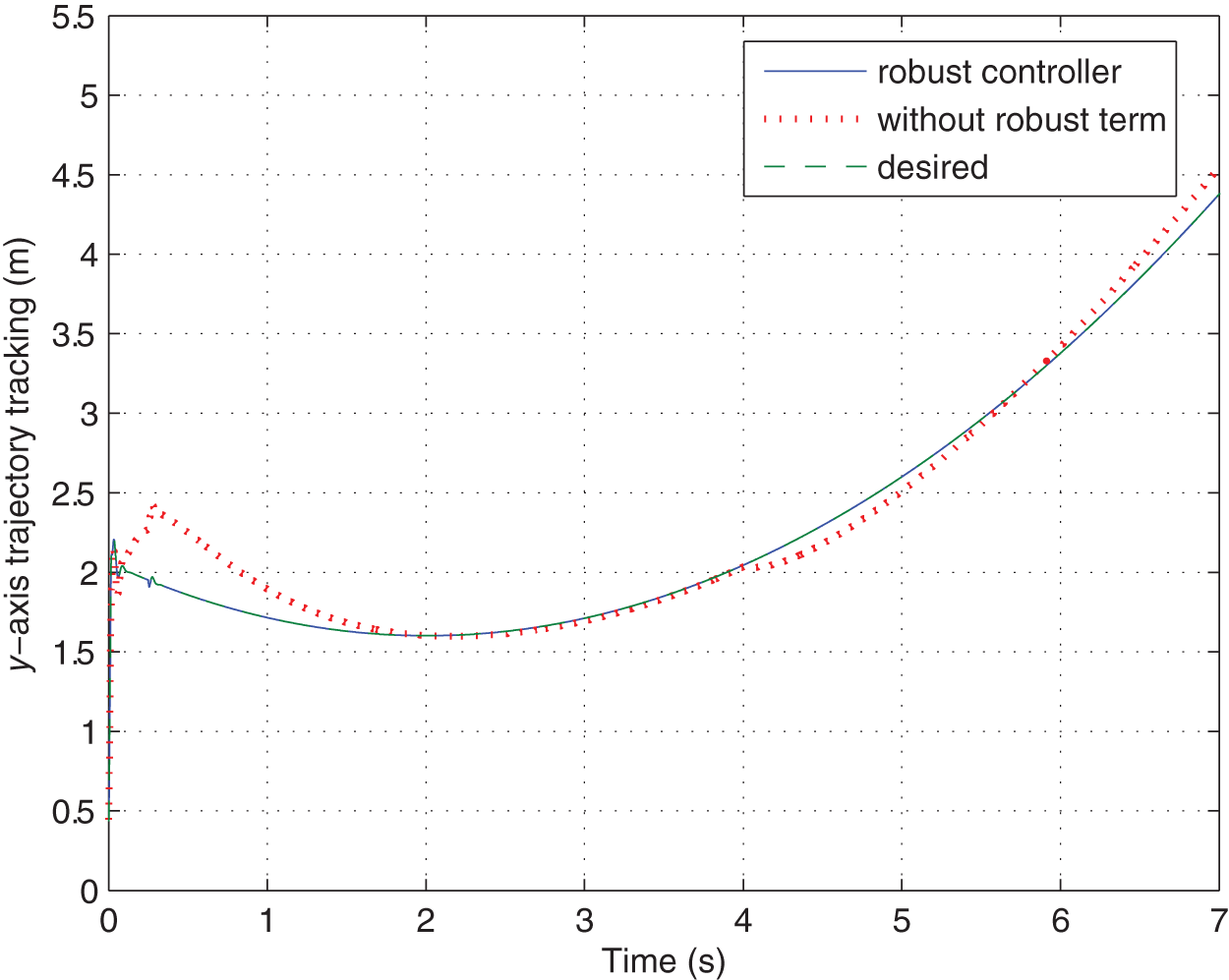
Position control responses with IPBIC along the - and -axes are plotted in Figures 3 and 4. In the absence of disturbance, overshoots mainly due to initial position deviations are observed during the initial s, however, these overshoots are quickly smoothed between 3 s and 4 s. When the disturbance is mixed at the fourth second, overshoots in both axes arise again, and proceed with periodical oscillations in the following 3 s.
Robust trajectory tracking in -axis.
Robust trajectory tracking in -axis.
As for the NN-compensated IPBIC method, initial overshoots are completely removed, and the trajectory tracking performances in the next s are fairly excellent. Again, when the disturbance is inserted at the fourth second, in contrast to the tracking without robust NN compensation, satisfactory trajectory tracking is always maintained. Thus, the proposed controller exhibits enough robustness to both initial position deviation and system uncertainties.
The results indicate that the proposed IPBIC method is able to perform accurate time-varying trajectory tracking in the absence of model uncertainties, and this tracking is no more guaranteed in the presence of disturbances. However, the proposed robust control scheme is proved to be effective enough in dealing with both initial position deviation and uncertain disturbances.
Time-varying force tracking
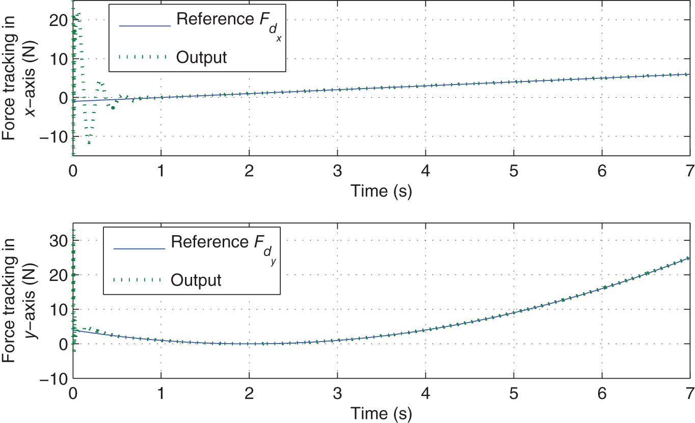
Corresponding to position control with NN-based IPBIC, the time-varying force tracking performances along the - and -axes are examined. Figure 5 shows the time-varying force tracking performances in both the - and -axes under the proposed NN-based IPBIC controller. Except for the moderate oscillations happening between and s, the time-varying tracking responses are rather accurate and stable. Potential reasons for the initial oscillations might be the initial position deviation of the end-effector, and the poor performance of the adaptive law at the beginning of the environment identification.
Time-varying force tracking in the - and -axes.
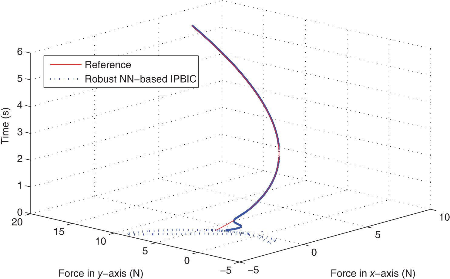
Figure 6 shows the resultant force tracking performance in the -plane. Again, oscillations are only observed at the beginning of the tracking, and then settle down within a short period of time. After this, the output converges accurately to its reference signal. The specified reference trajectory is precisely tracked in rectangular coordinates.
Time-varying force tracking in -plane.
The above results suggest that the developed IPBIC method is able to perform accurate time-varying force tracking, and the proposed NN controller is robust to the model uncertainties. Based on the robust position controller and the adaptive law for the uncertain environment, satisfactory force tracking is achievable with the proposed IPBIC, even in the presence of both internal and external uncertainties.
Conclusion
The problem of time-varying force tracking for -joint robotic manipulators in the presence of system uncertainties and unknown environmental variations has been investigated in this paper. A newly improved PBIC method is developed to perform time-varying force tracking. In order to compensate for the system uncertainties, a robust NN-compensated position controller is designed and the stability analysis is rigorously given. A simple adaptive algorithm is then developed for environment identification. Comprehensive simulation studies are performed upon a two-link robotic manipulator and the results confirm the effectiveness of the proposed robust NN-based force control scheme.
The improved position-based impedance controller is designed with a view to overcoming limitations of the traditional method in performing time-varying force control. It is also developed to extend the research of robot force control and to meet the requirements of time-varying force control in recent robot-based applications.
Footnotes
Acknowledgements
The authors are grateful to the anonymous reviewers for their valuable comments and suggestions.
Funding
This work was supported by the National Natural Science Foundation of China (grant numbers 61174038 and 61104064).
References
1.
AmirAAkbarK (2000) Force tracking of hydraulic manipulators within an impedance control framework. PhD Thesis, University of Manitoba, Canada.
2.
BascettaLRoccoP (2010) Revising the robust-control design for rigid robot manipulators. IEEE Transactions on Robotics26(1): 180–186.
3.
BigrasPLambertMPerronC (2012) Robust force controller for industrial robots: Optimal design and real-time implementation on a Kuka robot. IEEE Transactions on Control Systems Technology20(2): 473–479.
4.
ChiaveriniSSicilianoBVillaniL (2002) A survey of robot interaction control schemes with experimental comparison. IEEE/ASME Transactions on Mechatronics4(3): 273–285.
5.
FierroRLewisFL (1998) Control of a nonholonomic mobile robot using neural networks. IEEE Transactions on Neural Networks9: 589–600.
6.
FreemanCTRogersEHughesA. (2012) Iterative learning control in health care: Electrical stimulation and robotic assisted upper-limb stroke rehabilitation. IEEE Control Systems Magazine32(1): 18–53.
7.
GilardiGSharfI (2002) Literature survey of contact dynamics modelling. Mechanism and Machine Theory37(10): 1213–1239.
8.
GoldenbergAA (1988) Implementation of force and impedance control in robot manipulators. In: IEEE international conference on robotics and automation, pp. 1626–1632.
9.
HoganN (1985) Impedance control: An approach to manipulation. Part I – Theory. Part II – Implementation. Part III – Applications. ASME Journal of Dynamic Systems, Measurement and Control107(1): 1–24.
10.
HuangHBSunDMillsJK. (2008) Integrated vision and force control in suspended cell injection system: Towards automatic batch biomanipulation. In: IEEE international conference on robotics and automation, pp. 3413–3418.
11.
HuangHBSunDSuH. (2012) Force sensing and control in robot-assisted suspended cell injection system. In: Tauseef GulrezTHassanienAE (eds) Advances in Robotics and Virtual Reality (Intelligent Systems Reference Library, vol. 26). Berlin: Springer-Verlag.
12.
HuntKCrossleyF (1975) Coefficient of restitution interpreted as damping in vibroimpact. Journal of Applied Mechanics42(2): 440–445.
13.
JungSHsiaTC (1998) Neural network impedance force control of robot manipulator. IEEE Transactions on Industrial Electronics45(3): 451–461.
14.
JungSHsiaTC (2000) Robust neural force control scheme under uncertainties in robot dynamics and unknown environment. IEEE Transactions on Industrial Electronics47(2): 403–412.
15.
KrebsHIConroySSBeverCT. (2012) Forging mens et manus: The MIT experience in upper extremity robotic therapy. In: Neurorehabilitation Technology. London: Springer, pp. 125–140.
16.
LawrenceDA (1988) Impedance control stability properties in common implementations. In: IEEE international conference on robotics and automation, pp. 1185–1190.
17.
LeeSLeeHS (1991) Intelligent control of manipulators interfacing with an uncertain environment based on generalized impedance. In: Proceedings of the IEEE symposium on intelligent control, pp. 61–66.
18.
LewisFLJagannathanSYesildirekA (1999) Neural Network Control of Robot Manipulators and Nonlinear Systems. London: Taylor and Francis.
19.
LewisFLLiuLYesildirekA (1995) Neural net robot controller with guaranteed tracking performance. IEEE Transactions on Neural Networks6(3): 703–715.
20.
PelletierMDoyonM (1994) On the implementation and performance of impedance control on position controlled robots. In: IEEE conference on robotics and automation, pp. 8–13.
21.
RaibertMCraigJ (1981) Hybrid position/force control of manipulators. ASME Journal of Dynamic Systems, Measurement and Control103(2): 126–133.
22.
SciaviccoLSicilianoB (2000) Modeling and Control of Robot Manipulators. 2nd edn.Berlin: Springer-Verlag.
23.
SerajiH (1994) Adaptive admittance control: An approach to explicit force control in compliant motion. In: IEEE international conference on robotics and automation, pp. 2705–2712.
24.
SerajiHColbaughR (1997) Force tracking in impedance control. The International Journal of Robotics Research16(1): 97–117.
25.
SeulJHsiaTCRobertGB (2004) Force tracking impedance control of robot manipulators under unknown environment. IEEE Transactions on Control Systems Technology12(3): 474–483.
26.
SpongMWHutchinsonSVidyasagarM (2008) Robot Dynamics and Control. 2nd edn.New York, NY: Wiley.
27.
SunYNelsonBJ (2002) Biological cell injection using an autonomous microrobotics system. The International Journal of Robotics Research21: 861–868.
28.
ValencyTZacksenhouseM (2003) Accuracy/robustness dilemma in impedance control. ASME Journal of Dynamic Systems, Measurement and Control125: 310–319.
29.
VarkutiBGuanCPanY. (2013) Resting state changes in functional connectivity correlate with movement recovery for BCI and robot-assisted upper-extremity training after stroke. Neurorehabilitation and Neural Repair27(1): 53–62.
30.
VolpeRA (1990) Real and artificial forces in the control of manipulators: Theory and experiments. PhD Thesis, Carnegie Mellon University, PA.
31.
VolpeRKhoslaP (1993) A theoretical and experimental investigation of explicit force control strategies for manipulators. IEEE Transactions on Automatic Control38(11): 1634–1650.
32.
XieYSunDLiuC. (2008) An adaptive impedance force control approach for robotic cell microinjection. In: IEEE international conference on intelligent robots and systems, pp. 907–912.
33.
XieYSunDLiuC. (2010) A force control approach to a robot-assisted cell microinjection system. The International Journal of Robotics Research29(9): 1222–1232.
34.
ZengGHemamiA (1997) An overview of robot force control. Robotica15: 473–482.