
Abstract
Four-wheel independent drive electric vehicle cannot follow the driver’s command when one or more motor drive systems fail, which may lead to some serious accidents when the vehicle is running. In order to deal with this problem, a control strategy is proposed in this paper to maintain the stability of 4WID electric vehicle under the failure of motor drive systems. Firstly, failure states of motor drive systems are analysed and classified into Failure-Driving mode and Failure-Stopping mode according to the ability of the vehicle to drive safely. Secondly, a two-layer-control model is designed to maintain the vehicle performance and stability by controlling the remaining normal working motor drive systems for Failure-Driving mode. Thirdly, a control algorithm is designed to help the driver stop the vehicle safely in Failure-Stopping mode. Simulation based on Matlab/Simulink and veDYNA demonstrate that the proposed control strategy can maintain the stability of the 4WID electric vehicle in both Failure-Driving mode and Failure-Stopping mode.
Keywords
Introduction
As a solution for energy and environmental problems, electric vehicles (EVs) are receiving considerable attention (Maeda et al., 2012). Some solutions, such as the Tesla MODEL S, have performed extremely well with improved motor and batteries. A four-wheel independent drive (4WID) EV is a vehicle that is driven by four motors (in-wheel or hub) independently. The design of 4WID EVs permits packaging flexibility by eliminating the central drive motor, the associated transmission and drive-train components (including the transmission, the differential, the universal joints and the drive shaft; Tahami et al., 2004). As each wheel of 4WID EV can be controlled independently, yaw-moment control is used to improve its lateral dynamics (Demirci and Gokasan, 2013; Kim et al., 2008; Sakai et al., 1999; Tahami et al., 2003).
In 4WID EVs, the motor drive system consists of a motor, inverter and sensors (current sensors, speed sensors, etc.). As there are four motor drive systems in a 4WID EV, the failure rate of a 4WID EV is higher than an EV with one motor drive system, and the failure of motor drive systems may cause serious accidents when the vehicle is running (Mutoh et al., 2008; Wang and Wang, 2011).
In the research field of EVs, fault-tolerant control methods have been designed to ensure the system’s stability when speed sensors, current sensors, position sensors, etc., failure happens (Diallo et al., 2004; Gaied, 2014; Jeong et al., 2005; Parsa and Toliyat, 2007; Yang et al., 2010). These studies on fault-tolerant control focused on how to diagnose the fault state of the constituting components and how to compensate for the failed situation, but cannot deal with the situation when the drive system fails to generate a driving force (Mutoh and Tomita, 2006). Miyazaki and Ohmae (2005) studied the characteristics of vehicle motion when one inverter in the two-wheel independent drive EV breaks down, and control methods are proposed to improve the instability that occurs when one inverter breaks down. The failsafe performance of a front-and-rear-wheel independent drive-type EV has been studied (Mutoh and Nakano, 2012). Chu et al. (2012) proposed a rule-based strategy to enhance drive capability and lateral stability when failure happens in a distributed electric drive vehicle.
For a 4WID EV, the primary target of the control is safety. If motor drive systems fail, the remaining normal working motor drive systems can be used to maintain the driving performance as usual and drive safely. This study aims to give some contributions in this field; all of the motor drive failures are classified and analysed as Failure-Driving mode or Failure-Stopping mode. Furthermore, on the one hand, a control strategy is proposed to maintain the vehicle’s stability and desired performance in Failure-Driving mode; on the other hand, as the vehicle cannot be driven safely in Failure-Stopping mode, a control strategy is presented to help the driver stop the vehicle safely. The rest of the paper is structured as follows: system modelling is studied in the next section; we analyse the vehicle behaviour at the time of failure; the proposed control strategy is designed; our simulation and the results are introduced and finally, the main conclusion and future works are summarized.
Vehicle modelling
Vehicle model
The proposed method is based on an eight-degrees-of-freedom (8DOF) vehicle model, which is shown in Figure 1. Four degrees of freedom related to the vehicle body are longitudinal velocity (
Longitudinal motion:
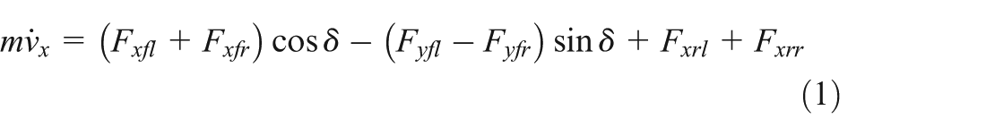
Lateral motion:

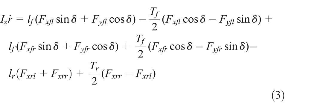
Yaw motion:
Roll motion:

Wheels rotational motion:
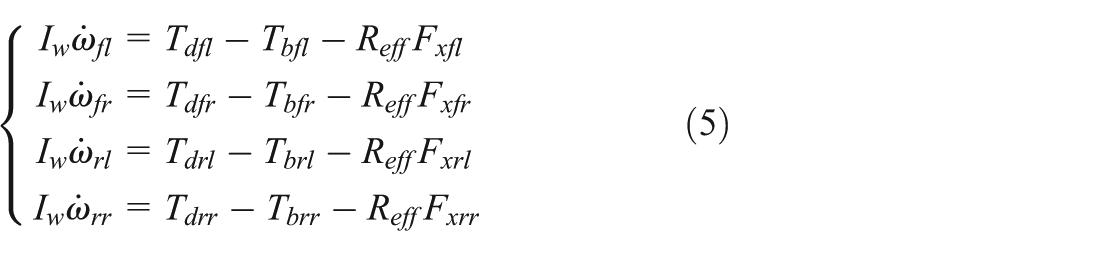
where m is the mass of the vehicle;
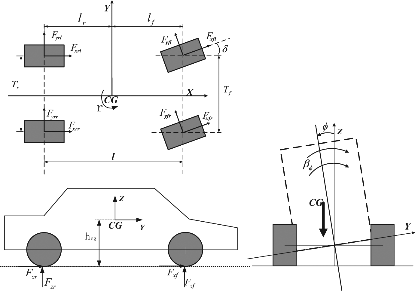
Eight-degrees-of-freedom (8DOF) vehicle model.
Tyre model
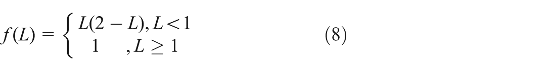
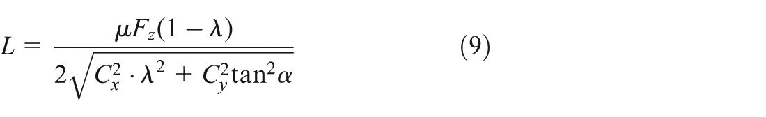
The tyre–road forces highly influence the vehicle dynamics. The tyre–road model proposed by Dugoff et al. (1970) is used in this study. For the Dugoff tyre model, the tyre forces are directly related to the tyre–road friction coefficient in more transparent equations than other tyre models (Rajamani, 2011). Let
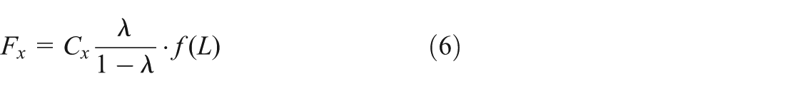
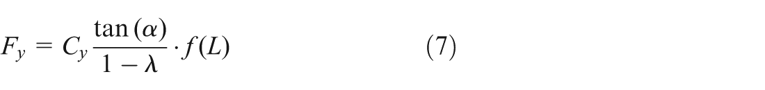
where
and
where
Vehicle behaviour analysis at the time of failure
For the purposes of controlling the vehicle when motor drive systems fail, we should first study the failure dynamics of vehicle. A simulation case is conducted to analyse the vehicle dynamics when the motor drive system fails. The known parameters of the 4WID EV model are listed in Table 1.
Specification of vehicle model.
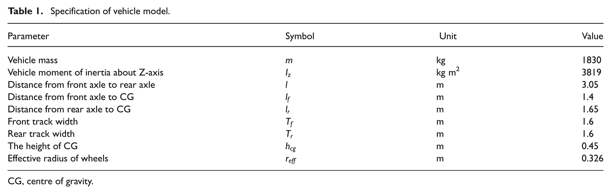
CG, centre of gravity.
In this simulation, the vehicle runs in a straight line and the drive torque of the four wheels is set to 40 Nm. At 2 s, the front left motor drive system fails and the drive torque of the front left wheel drops to 0 Nm. Simulation results are shown in Figures 2–5.
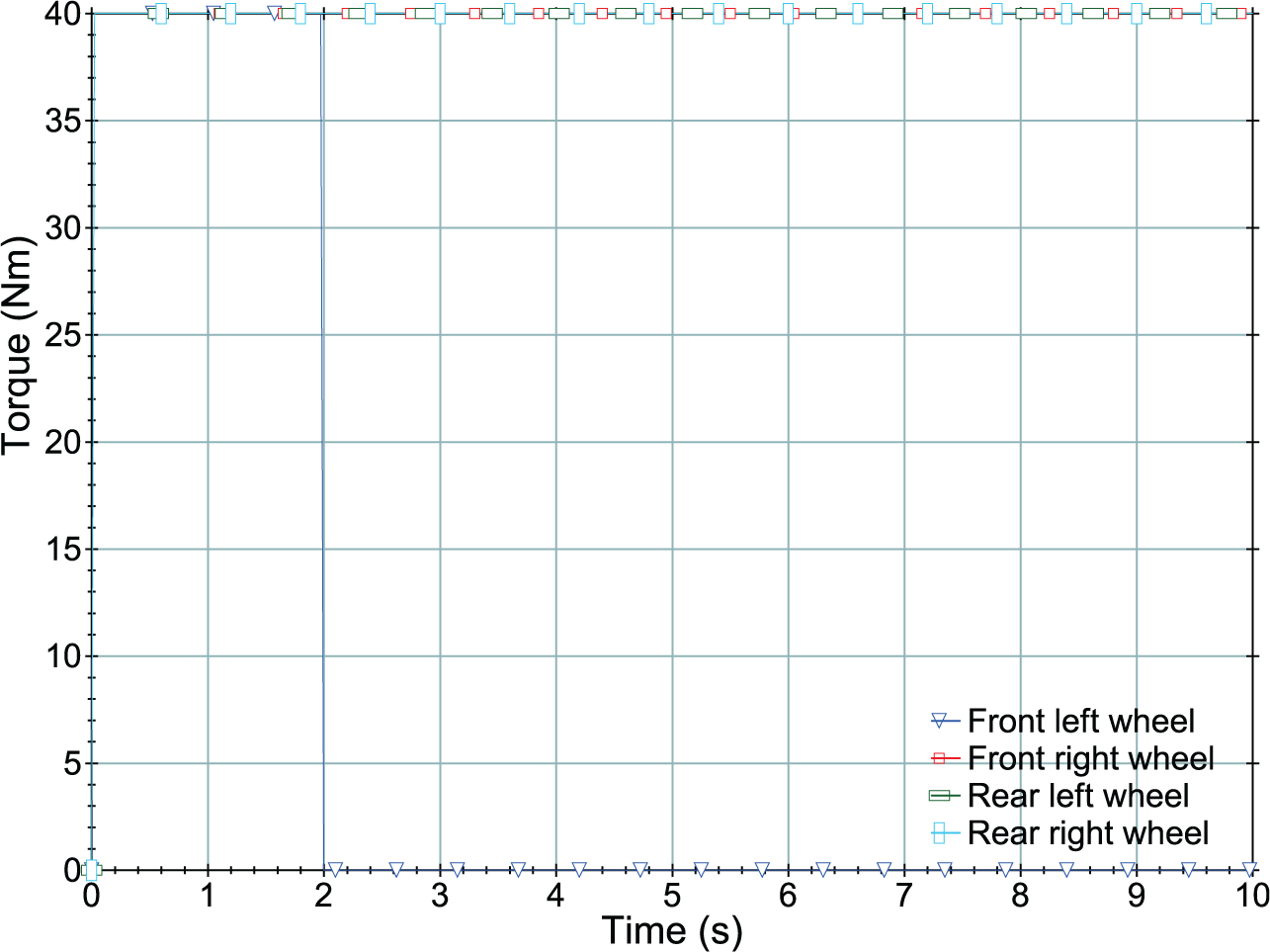
Drive torque in motor drive system failure simulation.
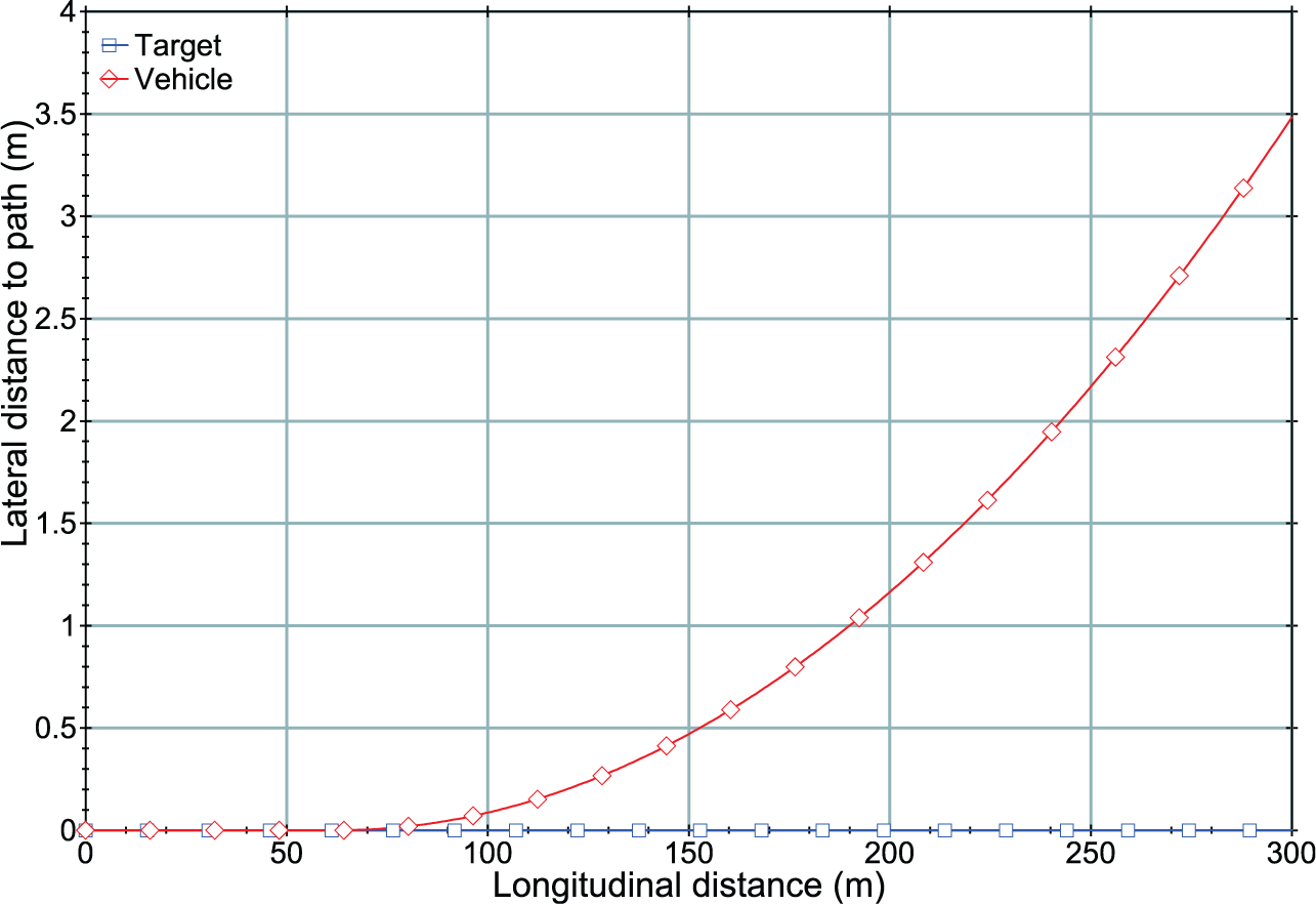
Vehicle trajectory in motor drive system failure simulation.
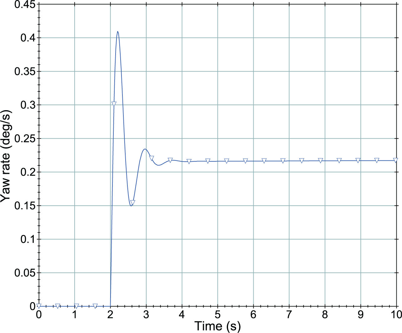
Yaw rate in motor drive system failure simulation.
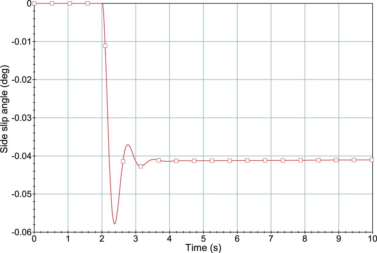
Side-slip angle in motor drive system failure simulation.
As is shown in Figure 2, before 2 s, the four wheel’s drive torque is 40 Nm. At 2 s, the front left motor drive system fails, and the drive torque of front left wheel drops to 0 immediately. Figure 3 shows that the vehicle rotates to left and cannot follow the target trajectory after failure occurs at 2 s. It can be seen from Figures 4–6 that a sudden change in yaw rate, side-slip angle and longitudinal speed are caused by the front left motor drive system failing at 2 s.
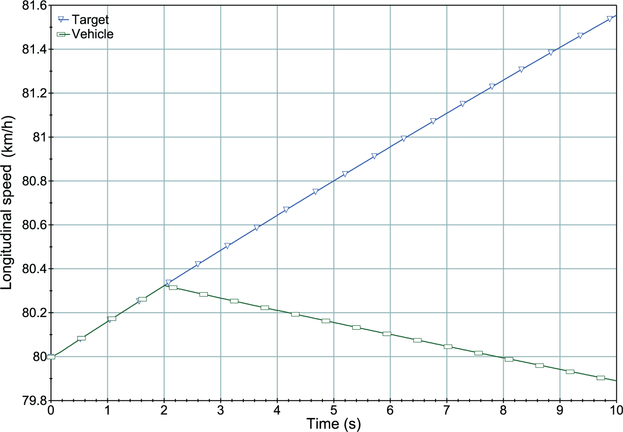
Longitudinal speed in motor drive system failure simulation.
It can be seen from the simulation results that the vehicle cannot follow the driver’s commands when the motor drive system fails. A control method should be designed to deal with this situation.
Control strategy design
Failure mode
Failure of the motor drive system may be caused by motors, inverters or sensors and Fault Detection and Isolation (FDI) of motor drive system is not discussed in this paper. If the failed motor is separated from the power supply after failure happens, the motor can still rotate freely under all the electric failures of the motor drive system, and the failed wheel can still be used as a non-driven wheel if the motor can still rotate freely. In this paper, only the electric failure of motor drive system is considered. It is apparent that the work state for each motor is a binary variable, either work or fail. The work state of each motor drive system is defined by
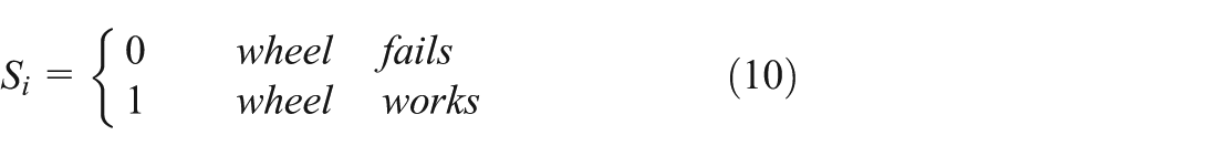
where

where is the failure mode.
The control algorithms for Failure-Driving mode and Failure-Stopping mode are different. In Failure-Driving mode, a Failure-Driving controller is proposed so that the vehicle can still be driven safely; In Failure-Stopping mode, a Failure-Stopping controller is designed to stop the vehicle safely.
Control for Failure-Driving mode
A double-layer-control-model is proposed in Failure-Driving mode – fuzzy logic-based direct yaw-moment control (DYC) in the upper layer and a torque distribution algorithm in the lower layer. Figure 7 shows the block diagram of the controller in Failure-Driving mode. In the upper direct yaw-moment control layer, a fuzzy-logic-based controller is designed to calculate the deviation of the drive torque; in the lower torque distribute layer, a driving torque calculator and a torque distributor are proposed to distribute the recalculated drive torque to the driven wheels.
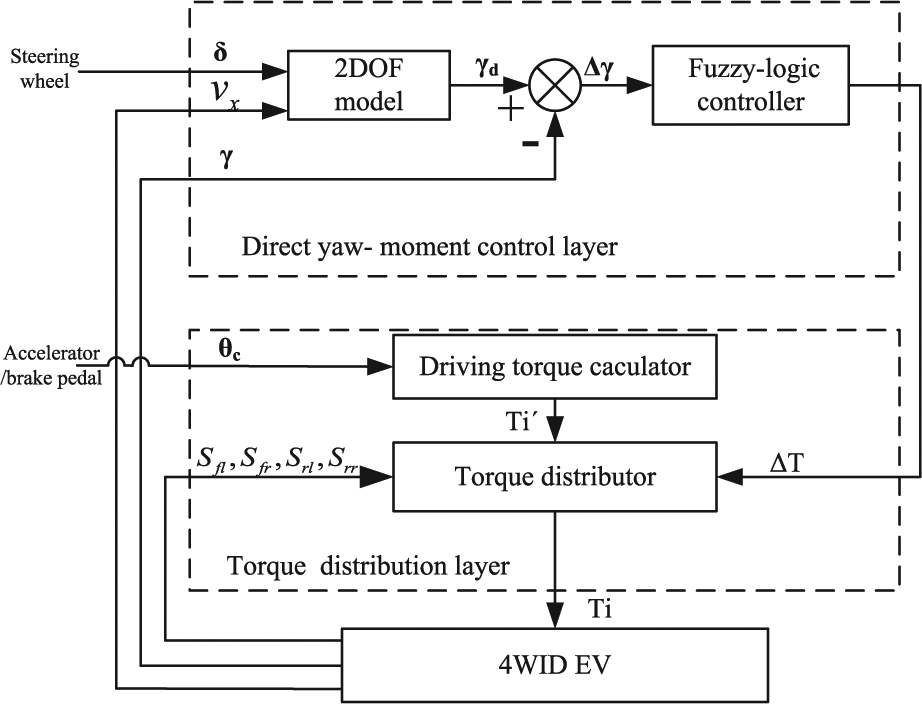
Controller for Failure-Driving mode.
The yaw rate of the vehicle and side-slip angle are in close connection with the vehicle’s stability, and yaw moment control is effective for enhancing the vehicle stability. The aim of yaw moment control is to adjust the yaw rate and side-slip angle to the desired yaw rate and side-slip angle. In our research, it is assumed that the side-slip angle is small, and yaw rate can reflect vehicle’s steady state when the side-slip angle is small. The two-degree-of-freedom (2DOF) vehicle model is widely used to calculate the desired yaw rate and side-slip angle in the application of active stability control of the vehicle (Boada et al., 2005; Rajamani, 2011; Tahami et al., 2003). Equations for the 2DOF vehicle model can be written as
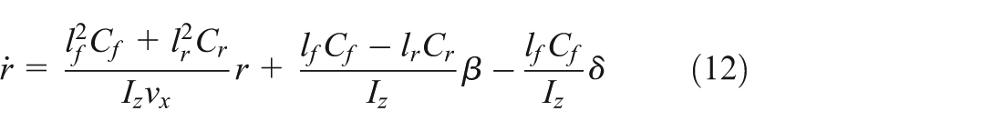
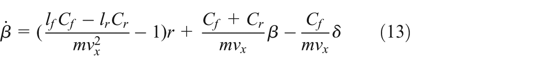
As can be seen from Equations (12) and (13), the 2DOFs are the motion of yaw rate and motion of side-slip. In our study, the 2DOF model is enough to calculate the desired yaw rate and side-slip angle. The equation between reference yaw rate and front wheel angle can be described as
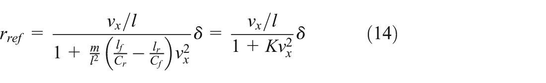
and
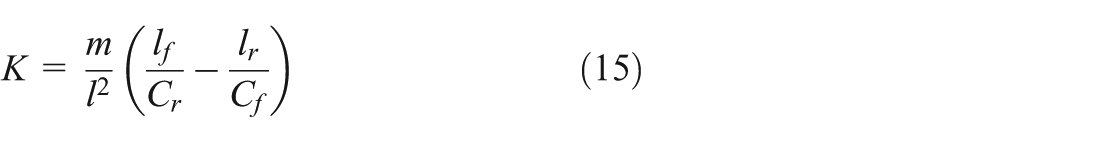
where K is the stability coefficient of the vehicle, and
where

DYC is a yaw moment control method that distributes proper traction and braking forces on the right and left tyres to provide a very effective means of stabilizing the vehicle characteristics. According the yaw motion equation in Equation (3), applying different torque to the left-side and right-side wheels can directly control the yaw rate. As the torque of each wheel can be adjusted independently, DYC can be applied to 4WID EV conveniently.
A fuzzy-logic controller is proposed in this paper to calculate the deviation yaw-moment (Figure 8). Fuzzy control is a non-linear control method, which can be used to deal with a complicated non-linear dynamic control problem (Efstathiou, 1988; Wang and Jordan, 1994). The number of applications of fuzzy logic to vehicle control has increased significantly over the last few years (Bauer and Tomizuka, 1996; Boada et al., 2005; Tahami et al., 2002).
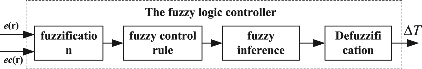
Structure of the fuzzy-logic controller.
There are two inputs in the fuzzy-logic controller:


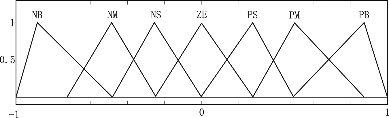
The number of linguistic variables describing the fuzzy subsets of a variable varies according the application. Fuzzy controllers with seven fuzzy sets are predominant, as they perfectly match a human’s perception of linguistic values (Kovacic and Bogdan, 2005). Seven fuzzy sets are used for both inputs

where NB is Negative Big, NM is Negative Medium, NS is Negative Small, ZE is Zero, PS is Positive Small, PM is Positive Medium and PB is Positive Big.
Various combinations of shapes and distributions of fuzzy sets result in a variety of possible controller structures. The triangular membership function with a linear distribution of fuzzy sets is the most widely used in the design of fuzzy logic controllers (Pedrycz, 1994). The triangular membership function is chosen as the membership function of the fuzzy logic controller’s inputs and output. The membership function for
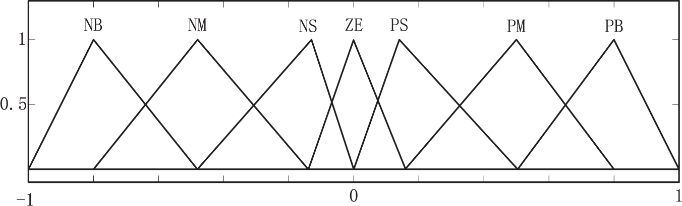
Membership function for yaw rate error.
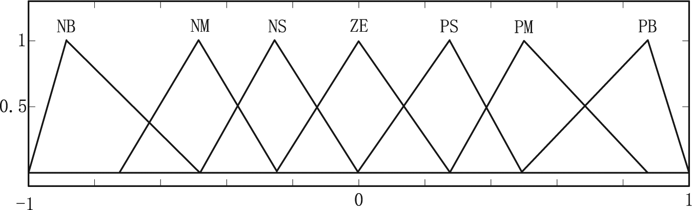
Membership function for yaw rate error of change.
For the fuzzy controller’s output, either an absolute controller output or controller output increment are usually generated. A controller output increment is used in this paper, and the control output

The membership function for
Membership function for deviation torque.
The rule-base is a set of rules that define the relation between the input and output of the fuzzy controller, and the rule-base can be found using the available knowledge in the area of designing the system. The knowledge required to generate the fuzzy rules can be derived from the understanding of the behaviour of the dynamic system under control and offline simulation. These rules in this paper are based on expert knowledge and the extensive simulations performed offline. The fuzzy rule-base for DYC is shown in Table 2.
Fuzzy rule-base for yaw moment controller.
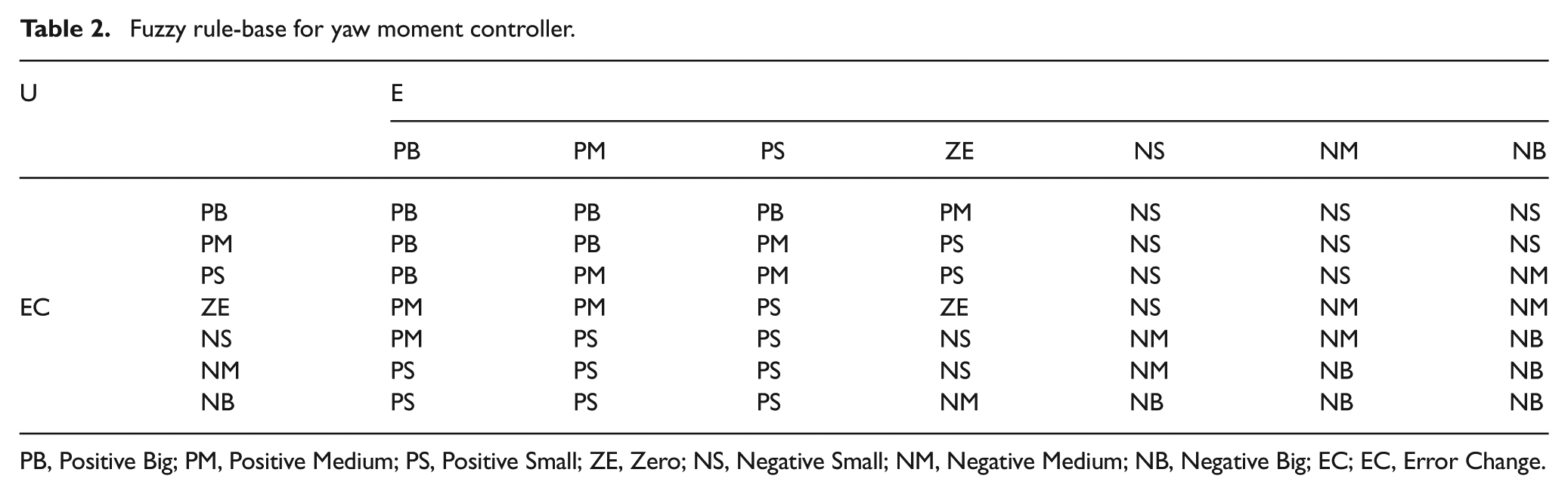
PB, Positive Big; PM, Positive Medium; PS, Positive Small; ZE, Zero; NS, Negative Small; NM, Negative Medium; NB, Negative Big; EC; EC, Error Change.
In Failure-Driving mode, if one motor drive system fails, the remaining three motor drive systems can be controlled, but the control of three driven wheels is complex, so we chose two wheels as the driven wheels and the other wheel as a non-driven wheel. In the situation when one wheel fails, the rule to choose driven wheels is defined as
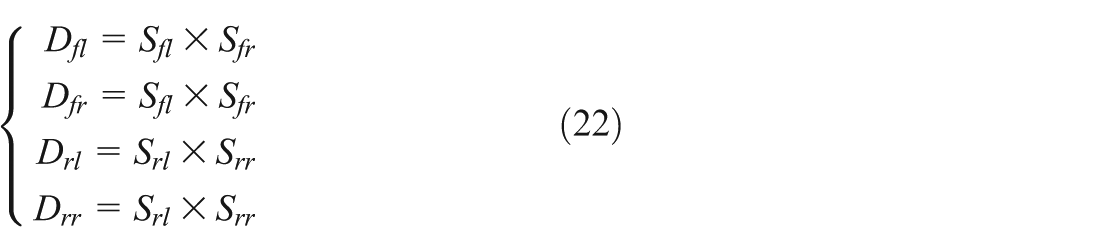
where
The driving torque calculator in Figure 7 is used to calculator the driving torque in Failure-Driving mode. is a one-dimension map where the input is the accelerator pedal position and output is the desired driving torque

In the torque distributor shown in Figure 7, the desired torque of the four motor drive systems can be expressed as
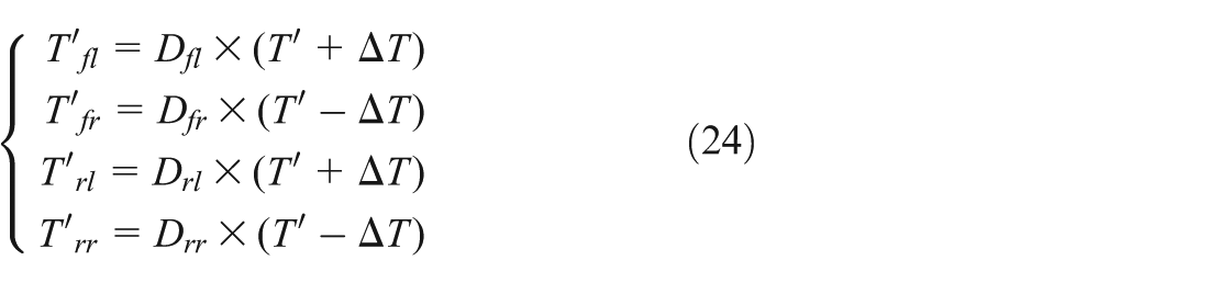
where

According the algorithms designed above, the control strategy for each failure case in Failure-Driving mode can be explained as follows. If the front left motor drive system fails,
Control for Failure-Stopping mode
In Failure-Stopping mode, because two motor drive systems in the same side fail or three motor drive systems fail at the same time, the vehicle cannot be driven normally. In the case of driving in a straight line, the drive torque of the four motor drives should be set to zero. If the vehicle is turning or changing lane in Failure-Stopping mode, the different torque on two sides of vehicle may cause deflection of driving directions. The vehicle should be stopped in Failure-Stopping mode, but the driver has the option to drive in a real-world application. In our study, a control strategy is presented to improve the performance by controlling the remaining normal working motor drive systems (Figure 12).
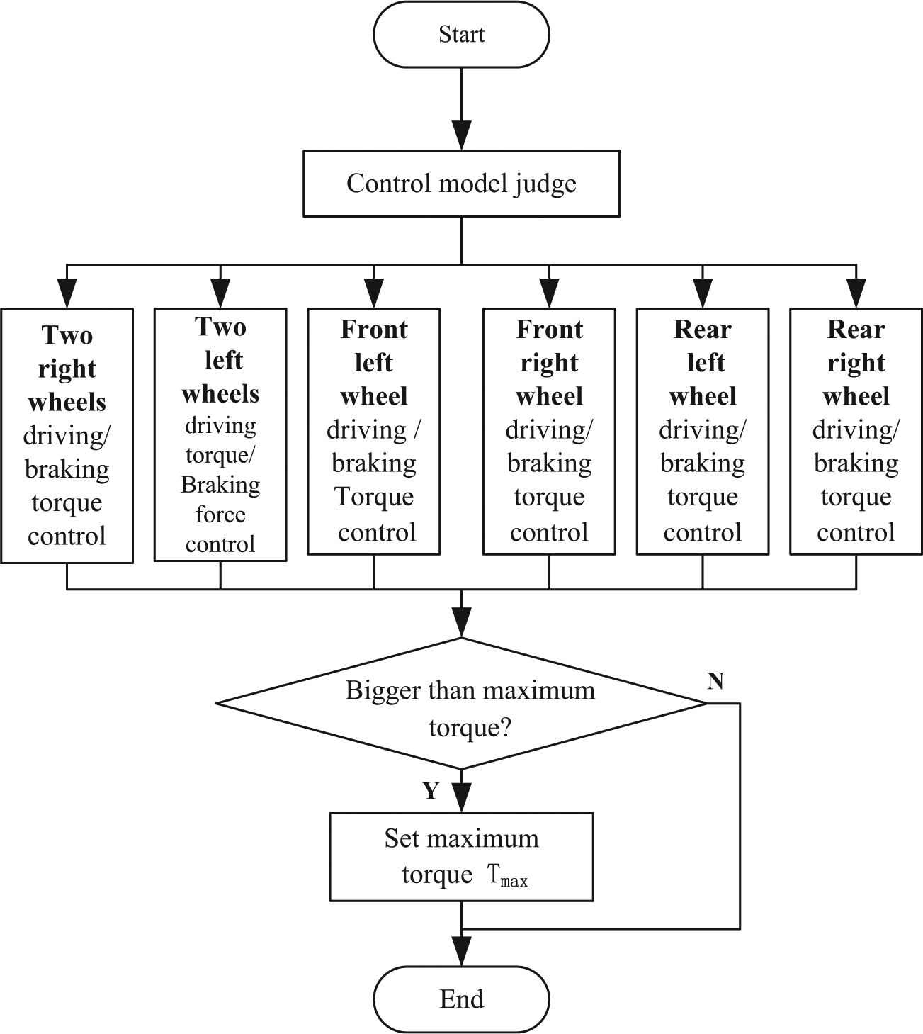
Flow chart of torque distribution in Failure-Stopping mode.
Taking the two left motor drive failures for an example, over-steering happens when vehicle turns left. By applying the braking force to the two right wheels, yaw moment decreases effectively and over-steering can be adjusted. The driving torque of the two right motor drive systems is reduced. The driving torque drops until it equals the maximum braking force torque. The driving torque remains unchanged after it is equal to the maximum braking force torque.
Simulation results
Two simulation cases are conducted based on Matlab/Simulink and veDYNA (Figure 13). The vehicle dynamics program veDYNA is developed and commercially distributed by TESIS DYNAware. The veDYNA simulation results show good agreement with real vehicle behaviour (Butz et al., 2002).
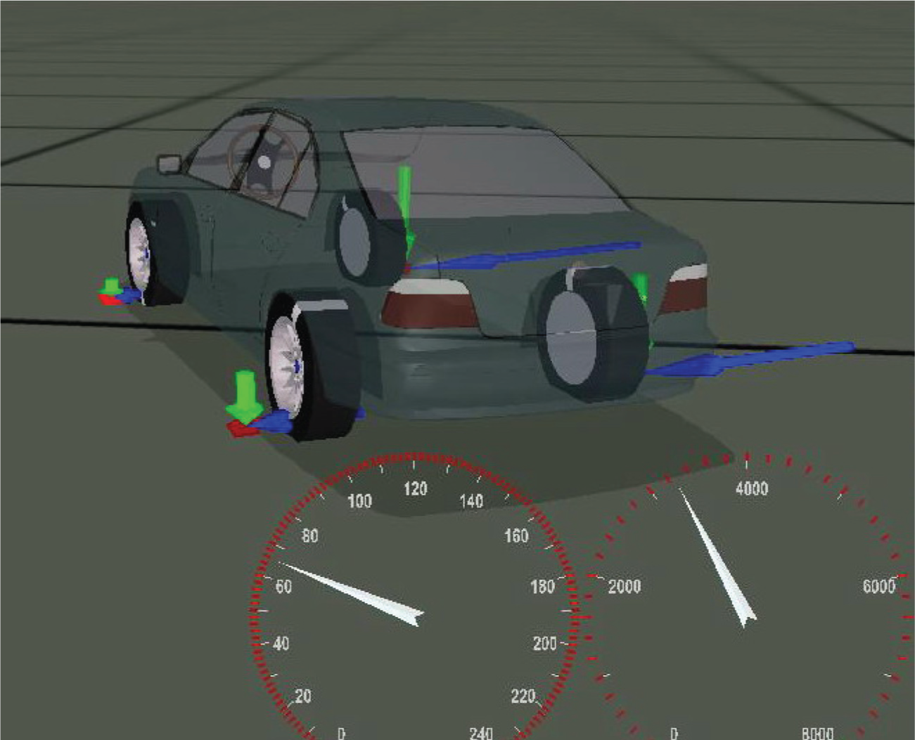
Human machine interface of the driving simulator.
Failure-Driving mode simulation
Friction coefficient on road surface is set to 0.8. The simulation case of Failure-Driving mode is set as follows: for 15 s, the vehicle accelerates after start-up until its speed is 80 km/h; the steering wheel is turned 70° to the left at 15 s; the front left motor drive system failed at 17 s.
Simulation results are shown in Figures 14–16.
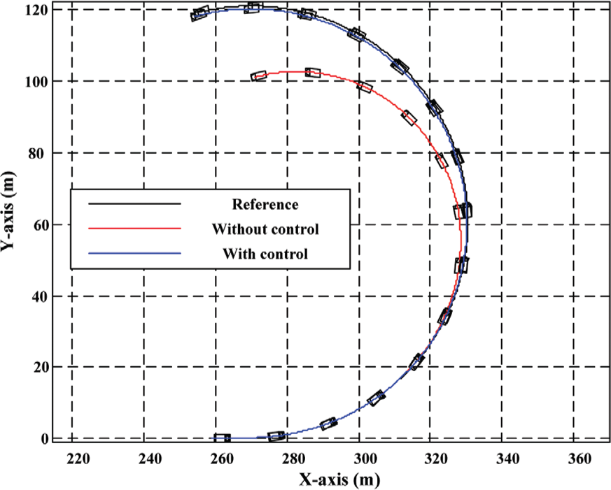
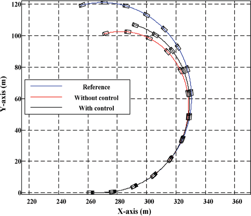
Vehicle trajectories in Failure-Driving mode simulation.
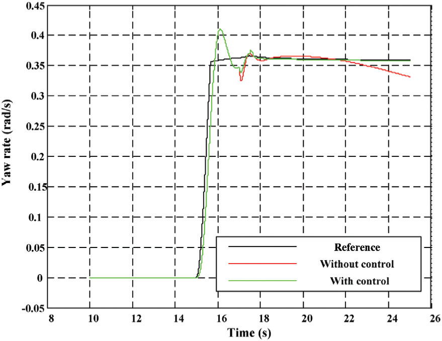
Yaw rate in Failure-Driving mode simulation.
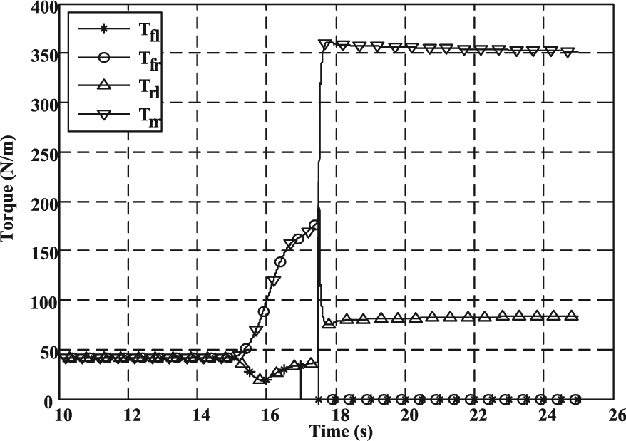
Torque in Failure-Driving mode simulation.
Figure 14 shows the trajectories of the vehicle. It can be seen that the trajectories with control can follow the reference, and the vehicle without control is over-steered because the front left motor drive system fails when the vehicle turns left. In Figure 15, after the failure happened, the value of yaw rate cannot follow the reference value without control, but the value of yaw rate can follow the reference value with control.
As is shown in Figure 16, torque of the front left wheel reduces to 0 after it failed at 17 s; the torque of the front right wheel reduced to 0 at 17.5 s because of the proposed control strategy adjusting; the torque of the two rear wheels are doubled to maintain normal driving performance. Meanwhile, the yaw moment controller adjusted the output torques of the two rear wheels to maintain the stability of the vehicle.
These simulation results show that the control strategy in Failure-Driving mode can maintain the performance and stability like driving normally. The simulation results of any other case of Failure-Driving mode are similar to this simulation case.
Failure-Stopping mode simulation
The simulation case of Failure-Stopping mode is set as follows: for 15 s, the vehicle accelerates after start-up until its speed is 80 km/h; the steering wheel turns 70° to the left at 15 s; the front left wheel and two rear wheels failed at 17 s. Simulation results are shown in Figures 17 and 18.
Vehicle trajectories in Failure-Stopping mode simulation.
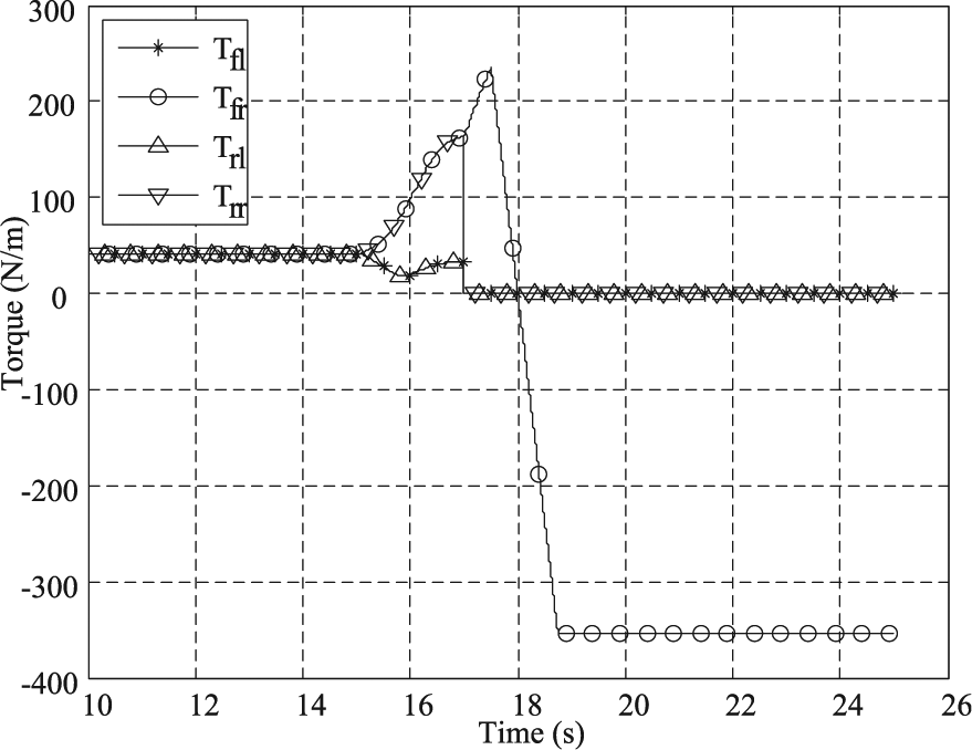
Torque in Failure-Stopping mode simulation.
As is shown in Figure 17, trajectories of the vehicle with control are different from the reference, but they are better than the vehicle without control.
As can be seen from Figure 18, the torque of the front left and two rear wheels reduces to 0 at once. The driver should stop the vehicle as soon as possible for safety.
Conclusion and future works
In this paper, the control strategy for a 4WID EV under failure of motor drive systems is studied. Two motor drive failure modes are defined for vehicles in terms of safety, and the control strategy is designed respectively to the two failure modes. Simulation results clearly demonstrate that the proposed control strategies can maintain the stability of the vehicle when the motor drive fails. This study would be useful to enhance the safety of 4WID EVs. For future work, a new design for control strategy may be investigated when the 4WID EV’s main ECU fails.
Footnotes
Declaration of conflicting interest
The authors declare that there is no conflict of interest.
Funding
This research received no specific grant from any funding agency in the public, commercial or not-for-profit sectors.