
Abstract
A novel device used to measure the velocity of a projectile for the military has been developed. This set of equipment based on the principle of statistics is composed of five groups of sensors. These five groups of sensors are symmetrically arranged to ensure that the groups of sensors measure the same point velocity, and the average value of the groups of sensors is regarded as the final test result. Compared with the traditional test method for projectile velocity, this method reduces the uncertainty of measurement by increasing the measurement samples. In this paper the F-test, T-test and variance are used to prove that the measurement value of this device is an unbiased, consistent and a valid estimation of the true value. Experiments are carried out over a wide operational range from 40 m/s to 2000 m/s velocity and from 4-mm to 12.7-mm calibre. The results show that the measurement uncertainty of this device is less than 1‰ (k = 2). This device can be suggested as a prior calibration in order to estimate other devices for measuring projectile velocity.
Introduction
The velocity of a projectile, as one of the exterior ballistic parameters, has been used extensively to monitor some important attributes of shooter and ammunition. Usually, velocity measurement of a projectile is categorized in three different methods, which are respectively radar, high-speed photography and zone-block. The radar measuring velocity is mainly based on the Doppler effect principle whereby the frequency difference between a transmitted wave and reflected wave is related to the velocity of the projectile (He and Li, 2009). Because high-speed photography recording frequency is fixed, the velocity of the projectile can be analysed by recording the frames and capturing the moving position of the object in the field of view. The zone-block method is widely used to measure the velocity of projectiles. As shown in Figure 1, the zone-block device consists of two targets. Each target with an induction area is perpendicular to the trajectory line, and when the projectile passes through this area, an induction signal will be generated. If the distance between two targets known as L, then by detecting the time difference Δt of these two induction signals, the velocity of an intermediate point between two targets can be calculated with Equation (1).

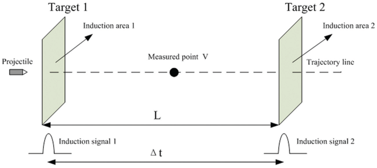
The principle of zone-block device measuring velocity.
According to the different principles of the induction area, zone-block can be divided into three types, including light screen, electromagnetic induction and switch. The main advantages of zone-block are that it is easy to design, has low maintenance cost and is inexpensive. However, there are also some disadvantages, such as the sensitivity not being high, it is susceptible to external stray light and shows poor vibration resistance. This study selects the light screen as zone-block where the laser is chosen as the light source to form a sensing area. The reason for choosing a laser as a light source is that the laser has the advantages of being stable, and having high energy and high sensitivity (Kang et al., 2011).
For velocity measurement, there is still a problem in there is no standard instrument directly calibrating the velocity measuring device, as the velocity is a calculated value (Wang et al., 2009). The most common method is to calibrate the zone-block by firing standard ammunition; the calibration of the ammunition fired is important for accuracy of measuring the projectile velocity device and determining the indication error, but there is a velocity error of 2–5% for standard ammunition because of inconsistency, so the calibration precision is difficult to guarantee. In this study, we hope not only to improve the test precision, but also hope that this set of equipment can be used as a standard to calibrate other zone-block devices.
Theory and method
Statistical theory and method
In this study, the measurement principle of the device is shown in Figure 2. Through the trajectory line, five groups of zone-block are symmetrically arranged at both sides of the monitored point. For each shot, five velocity values will be obtained.

Measuring principle.
These five values can be calculated by Equation (2), where v is the velocity, j the range and Δt the time difference.

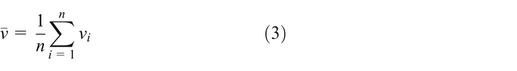
The average velocity of the five-group zone-block can be calculated by Equation (3), where n is the total number of the zone-blocks. In this study, n is equal to five.
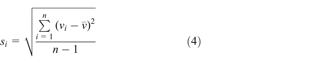
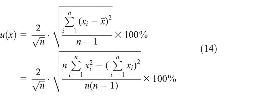
The standard deviation of each group is evaluated with the Bessel formula, as shown in Equation (4).
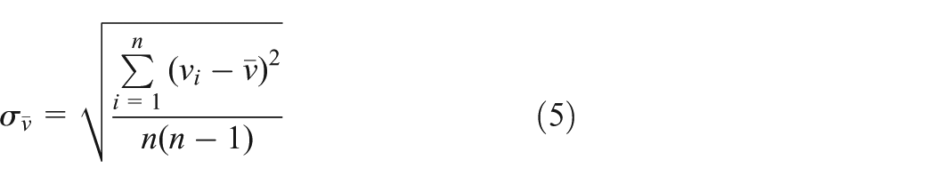
The standard uncertainty of the average velocity can be evaluated by Equation (5).
Based on the above analysis, the velocity measurement accuracy of the measured point can obviously be improved by increasing the number of zone-block devices, and when n = 1, this is the common used method.
Unbiased, consistent and valid test
It should be discussed whether the result calculated by Equation (3) can be regarded as an estimation for true value, in an unbiased, consistent and valid test.
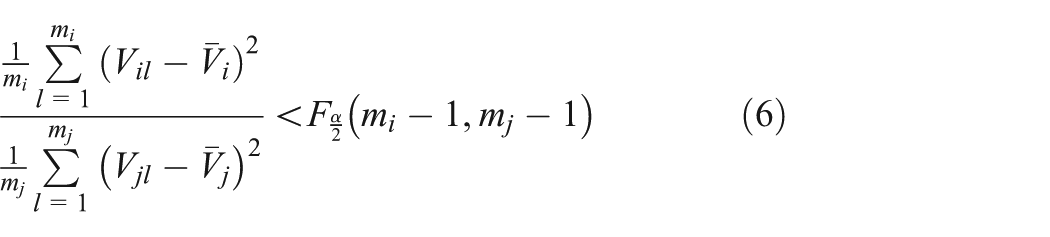
If the mathematical expectation of the estimators is equal to itself, they is unbiased estimators. When the sample number is limited, whether the estimator is unbiased can be checked by the F-test. Adopting the F-test method, if the Equation (6) is true, it can be considered that the result of Equation (3) is unbiased compared with other groups. In Equation (6), m is sample size for each experiment,
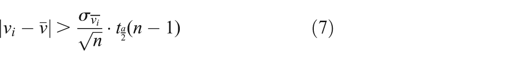
Howell (2012) and Chen et al. (2005) have used the T-test as a method of consistency estimator, so the method is used in this study. The T-test is used to infer the probability difference happening with the t-distribution theory, and then the difference of the average value is estimated. The projectile velocity measured by each zone-block obeys normal distribution. The consistency can be decided by Equation (7), wherein
The test results

Systems architecture
The system architecture consists of five groups of zone-blocks, the frame, the signal conditioning module and the data acquisition equipment, shown in Figure 3. The detailed architecture will be explained in this section.
System architecture.
A zone-block, as shown in the Figure 4, is composed of two parts that are the light-emitting portion and the photosensitive part. The frame size of the zone-block is 1360×920 mm and the internal dimension of zone-block is 800×800 mm. In the light-emitting part, many lasers pass through the optical lens and the diaphragm, and form a light area of a thickness of 3 mm.
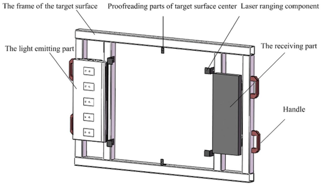
Zone-block.
The performance of the light-emitting portion is shown in Figure 5. The photosensitive part comprises a plurality of photoelectric sensors, as shown in Figure 6 (Dabov et al., 2007). One piece of the photosensitive device has 16 photosensitive pixels. The signal processing circuit is composed of a photoelectric conversion, the amplifier circuit, a comparing circuit and a shaping circuit (Kejzlar and Fischer, 2003). The principle block diagram is shown in Figure 7. A projectile target occlusion causes a light changing flux and a photoelectric sensor will convert the changing flux into a current signal. The current signal is finally converted into a pulse signal output after the signal processing circuit (Garinei and Marsili, 2013).
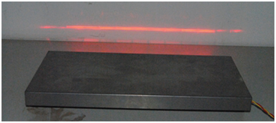
The performance of the light-emitting portion.
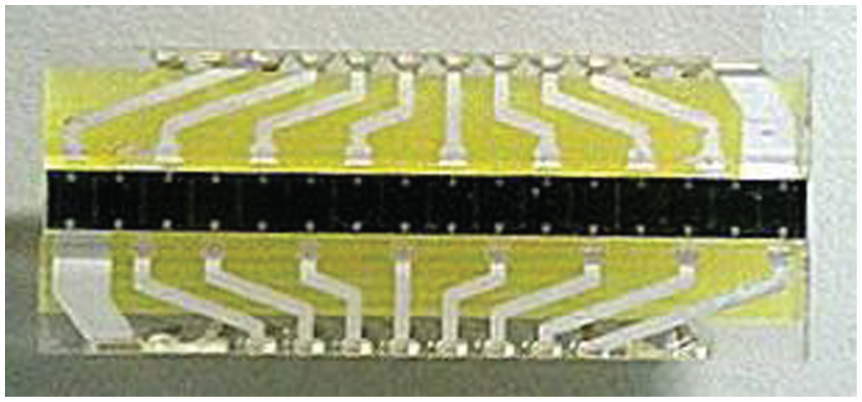
Photosensitivity.

Signal processing circuit block diagram.
The device uses an NI data acquisition system with a timer of 60 MHz frequency. The measurement accuracy of the timer depends on the frequency. LABVIEW provides special engineering tools to gain information from the data obtained by the hardware platform.
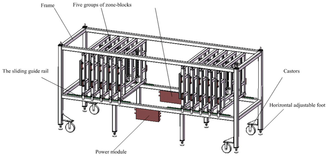
The framework is built of aluminium alloy with high strength and rigidity, as shown in Figure 8. The section dimensions are 80×80 mm. The outer frame section adopts a special link part and a fasteners link. The lead rail providing support and installation guide is mounted, the dimensions of which are 3980×1360×1620 mm (length×width×height).
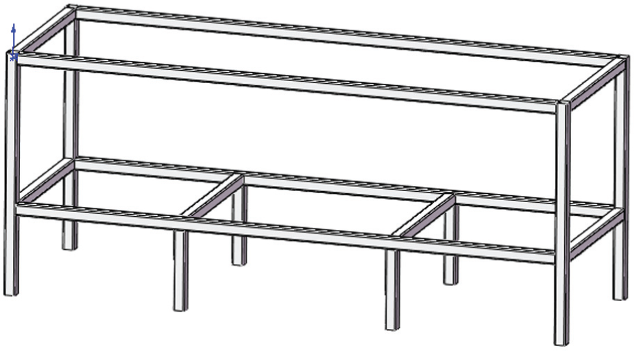
The framework built with aluminium alloy.
The conditioning signal is sampled by a data acquisition system, and the test data display, analysis and processing through the special test program written (Qiu, 2013).
Uncertainty analysis
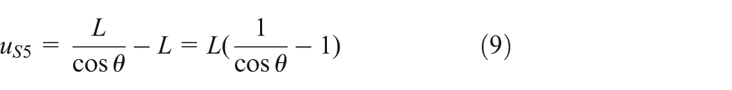
As seen from Equation (1), the uncertainty of the velocity is determined by the distance L and the time difference Δt. Measuring the distance uncertainty is composed of five parts: 1) the error
The laser ranger used to measure the distance has an accuracy of 1 mm, so
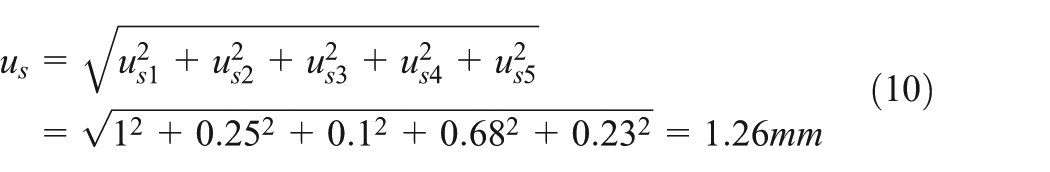
From the above analysis, the composite error can be obtained by Equation (10) (Fei, 2010).
The time difference Δt uncertainty is composed of two parts, including the uncertainty of the instrument measuring time and the uncertainty caused by the electrical characteristics differences from the signal processing circuit. As the time difference is measured by the data acquisition device with a sampling frequency of 60 MHz, the maximum measurement error is about 0.0167 µs, a measuring time uncertainty so small that can be neglected. The differences in electrical characteristics can cause the two timing signals from a group of zone-blocks to generate a phase difference.
Based on strictly screening the electronic components and ensuring consistency of each functional unit, the uncertainty
The temperature, pressure and crosswind must influence the measurement result in measurement as a type B uncertainty, but the influence of the temperature and pressure is so small that it can be neglected in the measurement. When test is carried out indoors, it is not necessary to consider the influence of crosswinds because of the windless condition; the calibre of projectile is small and the body of projectile is based on the principle of reducing air resistance. The wind speed is negligible when the test is carried out outdoors, so the uncertainty caused by crosswind is much smaller than that caused by instruments and can be neglected.
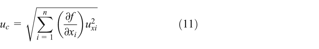
According to Equation (11) of the combined standard uncertainty, the standard uncertainty
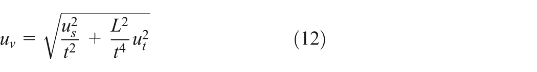
If the zone-block distance L is regarded as 1500 mm and the maximum velocity of projectile v is 2000 m/s, the standard uncertainty of velocity can be calculated by Equation (12). So the uncertainty of a group of zone-block can be confirmed as less than 0.2% by Equation (12).
From the above analysis, for actual operations considering the uncertainty of various factors for measurement, the measurement uncertainty of a group of zone-blocks is better than 0.2%. If the measurement uncertainty of a group of zone-blocks is
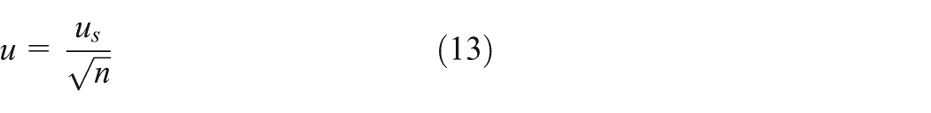
Taking the
Experimental investigation
Experimental
In order to check whether the system measurement uncertainty meets the design requirements, the experimental investigations are carried out indoors and outdoors. The indoor test objects are those weapons with different calibres of 5.56, 5.8 and 7.62 mm, and the velocity range is from 400 to 1000 m/s. Outdoor experiments are conducted on 12.7-mm and 30-mm-calibre weapons and the examination velocity range is from 1000 to 2000 m/s.
As shown in Figure 9, the system is assembled in the room with the requirements that each zone-block is perpendicular to the horizontal plane and trajectory, so the error is not more than ±1°. Regarding the measured point as the centre, the five groups of zone-blocks are arranged symmetrically to ensure that the groups of zone-blocks measure the velocity of the same point.
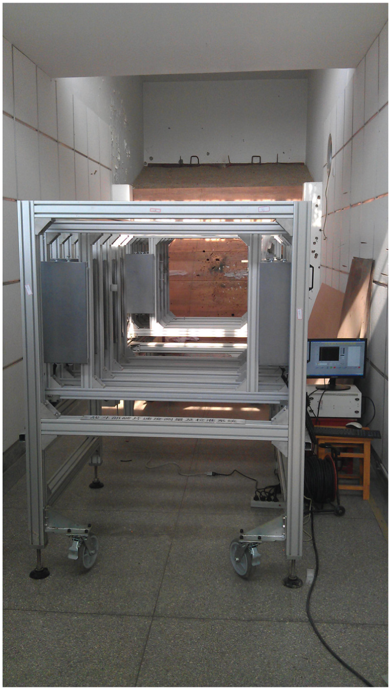
The system assembled in the room with these requirements that each zone-block is perpendicular to the horizontal plane and trajectory.
Figures 10 and 11 for the shooting scene firing test requires each group to launch 10 rounds and in 20 minutes the shooting is over. Data acquisition and processing software programmed in the data acquisition system can give the velocity measured by each zone-block, the average velocity of the five group targets and its uncertainty.
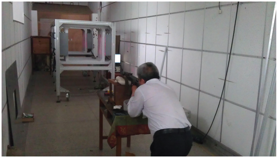
The 4-mm air gun weapons firing test are carried out indoors.
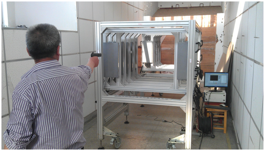
The 5.56-mm rifle weapons firing test are carried out indoors.
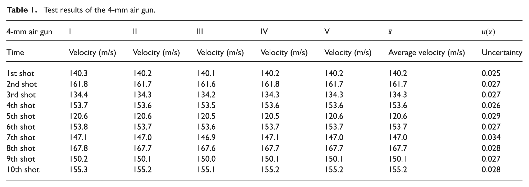
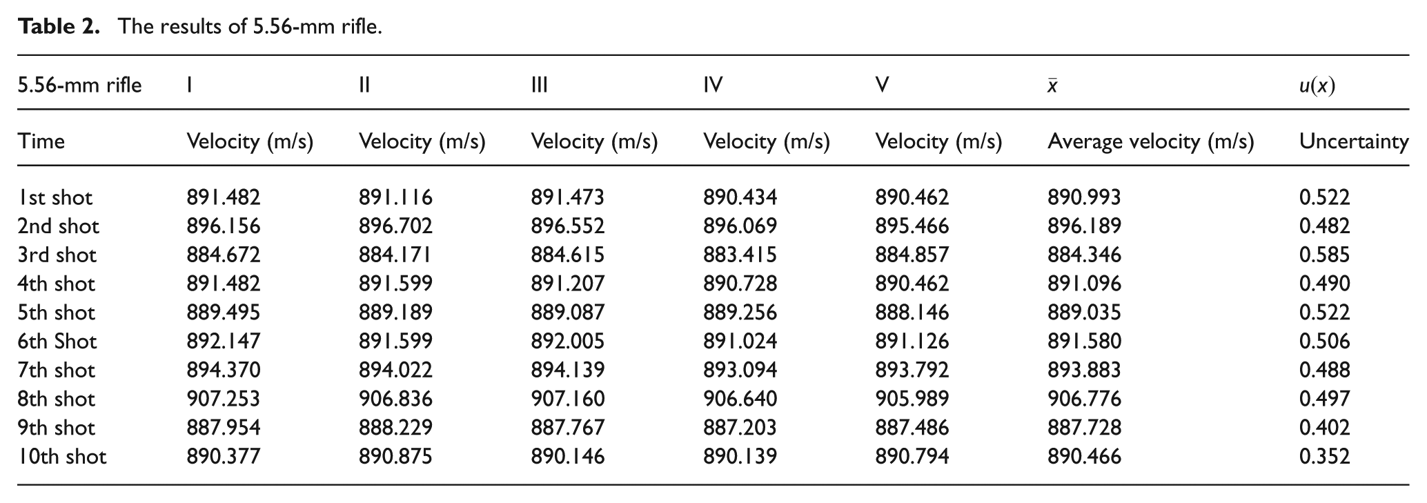
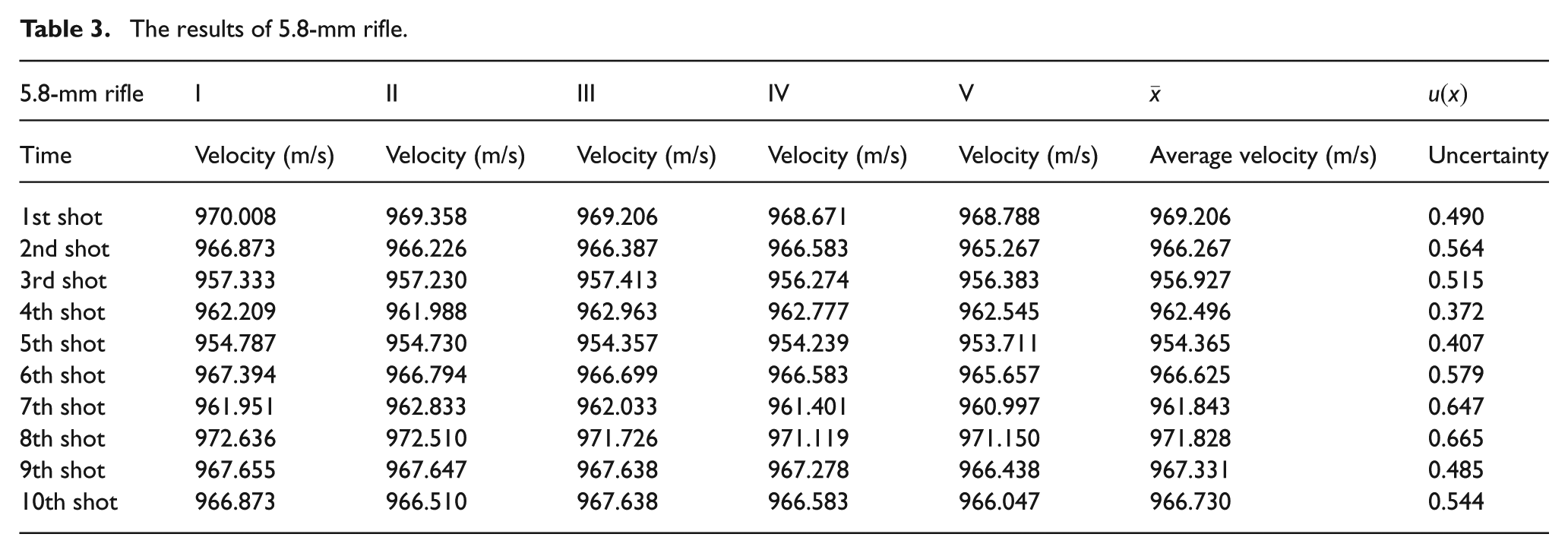
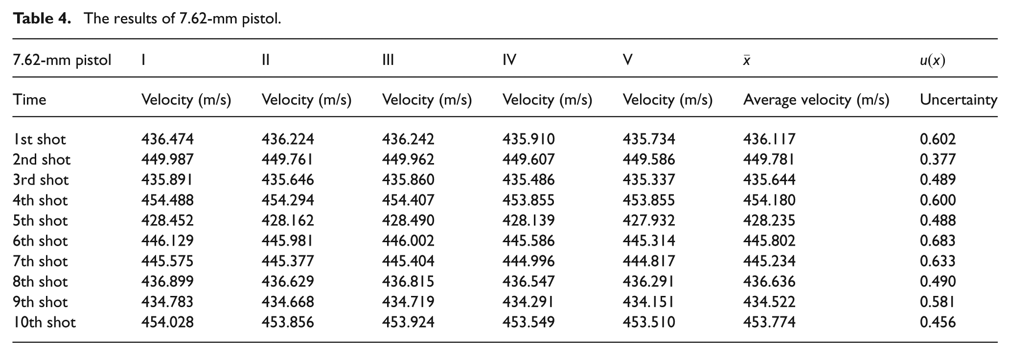
The test results are shown in Tables 1–7. The uncertainty (k = 2) of
Test results of the 4-mm air gun.
The results of 5.56-mm rifle.
The results of 5.8-mm rifle.
The results of 7.62-mm pistol.
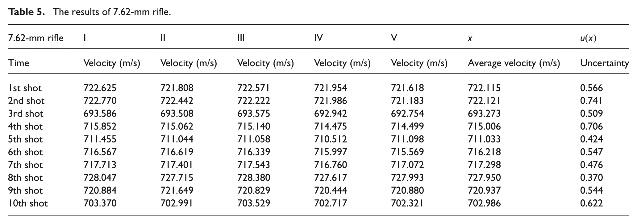
The results of 7.62-mm rifle.
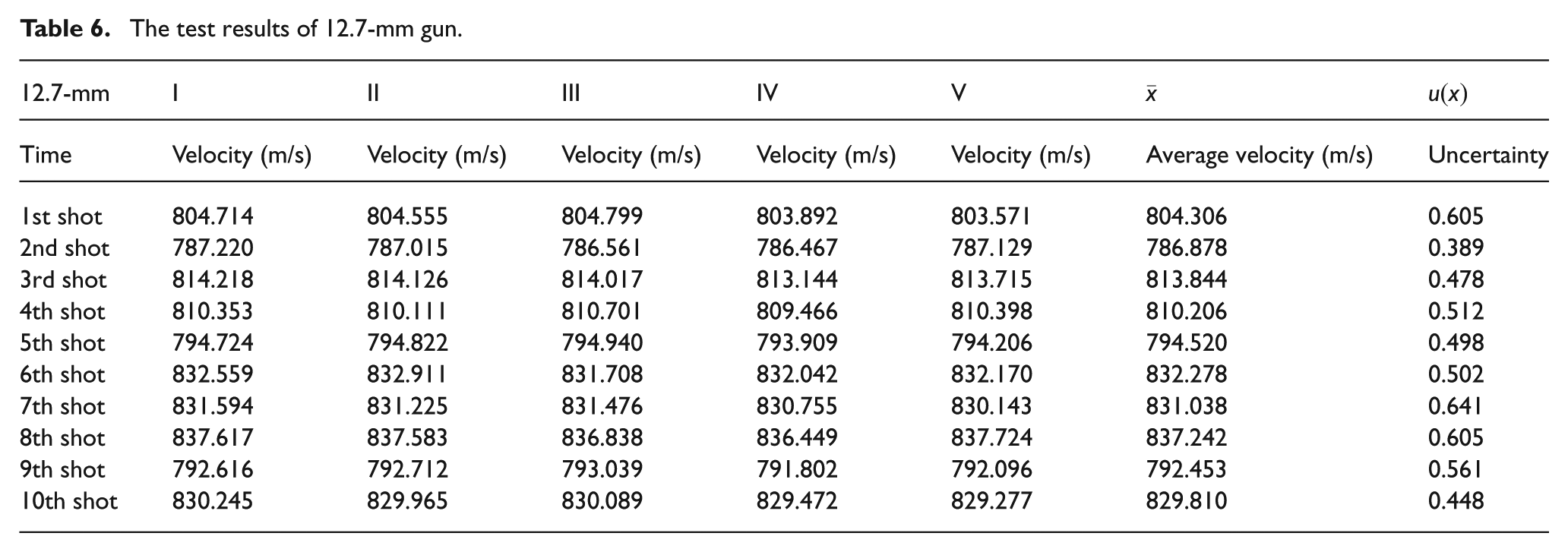
The test results of 12.7-mm gun.
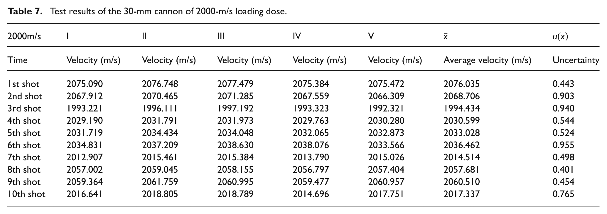
Test results of the 30-mm cannon of 2000-m/s loading dose.
The velocity, average velocity and uncertainty with 4-mm calibre air gun firing are measured for each zone-block device.
From the test and calculation results in the tables, the uncertainty of the system can meet 1‰ (k = 2) requirements.
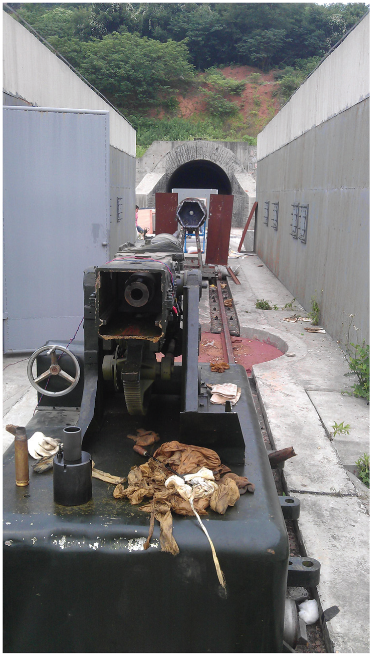
As shown in Figures 12 and 13, the 12.7-mm and 30-mm-calibre weapons firing tests are carried out outdoors.
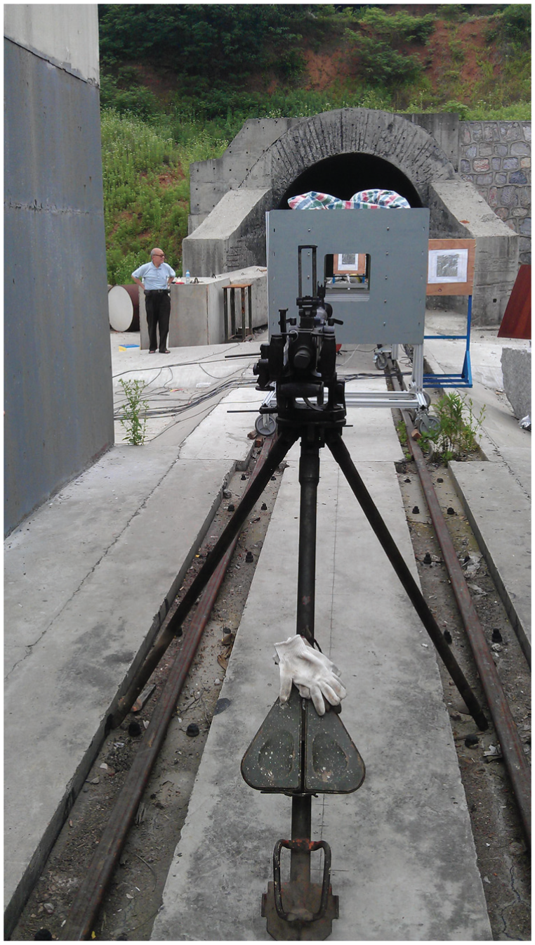
The 12.7-mm-calibre weapons firing test are carried out outdoors.
The 30-mm-calibre weapons firing test are carried out outdoors.
Statistical analysis
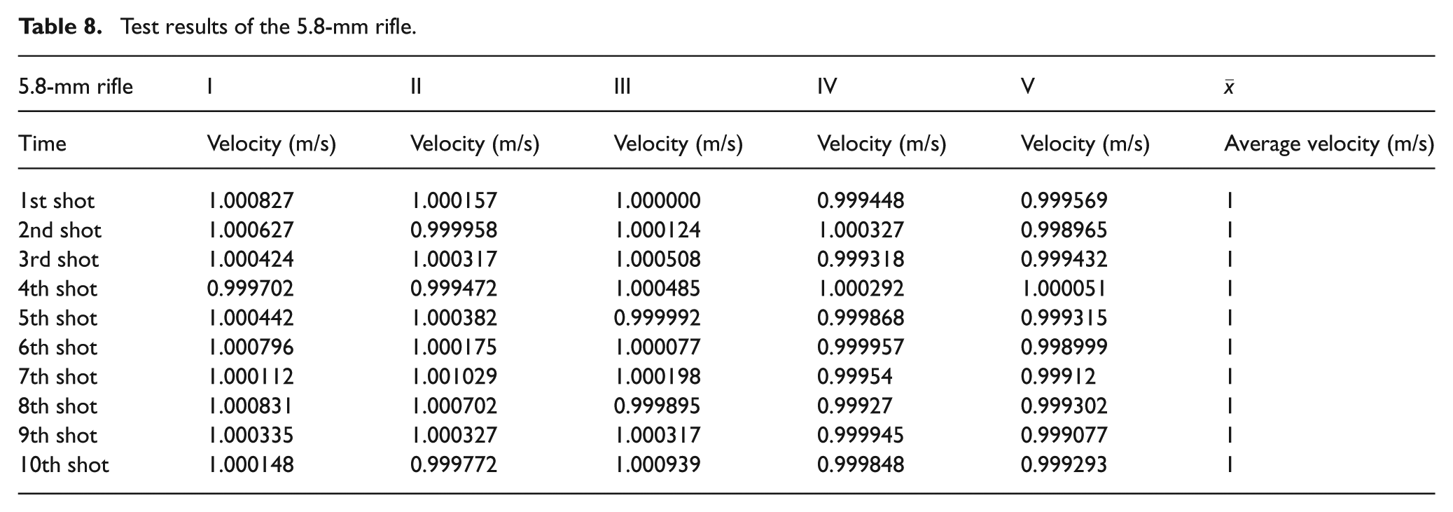
In order to verify that the measurement result is unbiased, consistent and valid for this true velocity, the methods described above may be put to the test. The method of analysis is the same in each one, so here only the 5.8-mm test results are analysed. Table 3 is the test results of the 5.8-mm rifle. By the normalization of processing, Table 8 can be obtained.
Test results of the 5.8-mm rifle.
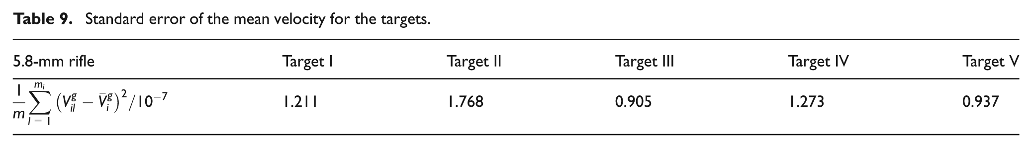
The average velocity standard deviation of each target is shown in Table 9, in which it can be seen that the standard deviation is not equal for each one. If the significance level
Standard error of the mean velocity for the targets.
Data analysis results based on F hypothesis test for each target.
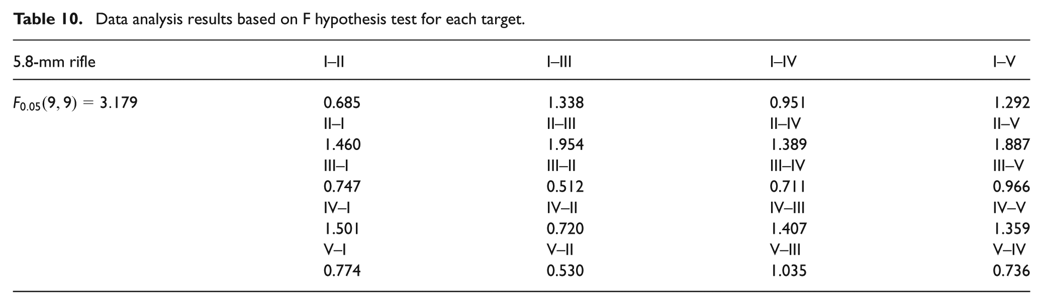
From the above results can be seen, for different kinds of projectile data to calculate the F hypothesis testing results greater than the I–V target, the ratio between any two target standard deviation can be obtained, and therefore the target accuracy requirements.
With Equation (7), the data in Table 8 can be estimated. If the significance level
T-test results.
As shown in Table 11, the significance level
If Equation (8) is a criterion for the validity of estimated value, it is obviously for Equation (3) that
In summary, by analysing the normalized firing data, the measured velocity in this study is unbiased, consistent and valid for the true velocity value.
Conclusions
This set of equipment based on the principle of statistics to design a projectile testing system, compared with the traditional velocity measurement system, is effective for improving test precision.
The equipment frame for the aluminium section is built and equipped with rubber wheels, a zone cutting device of the modular design, and has convenient disassembly, assembly and movement.
A sensor that comprises a laser-generating, photoelectric induction is a silicon photocell array sensor with higher strength and better stability, and can improve the test sensitivity, detect the target object diameter over 2 mm and detect a maximum speed range of 2000 m/s.
Because mostly a derived quantity for speed and not speed directly calibrated, and equipment has a high precision, so the system can be used not only as the projectile velocity detecting device, but also can be used for the calibration of other projectile velocity measurement equipment.
Footnotes
Conflict of interest
The authors declare that there is no conflict of interest.
Funding
This research received no specific grant from any funding agency in the public, commercial or not-for-profit sectors.