






Abstract
The aim of the study is to develop a measuring and presetting system for tool electrodes used for machining rimmed turbine blisks. A data-sampling method based on voltage monitoring was established as the foundation of this study. The proposed system, which consisted of three parts (mechanical, electric control and computer numerical control system software), was then realized. The method for extracting characteristic points from the theoretical model of the tool electrode and the bicubic B-spline algorithms for reconstructing the actual model of the tool electrode were established. A simulation analysis of the surface deviation was conducted to verify the extracting method and the algorithms. Next, a suitable accuracy evaluation method was developed to evaluate the accuracy of the tool electrode. Several experiments were performed to verify the performance of the system. Currently, the system is applied to practical production and has shown satisfactory results.
Introduction
A rimmed turbine blisk (Figure 1) is a key part of an engine. The blisk has numerous blades; moreover, its rims, blades and hubs are all machined from the same piece of metal (Figure 1a). Every blade has a free-form surface with a complex shape and acutely changing curvatures, and the channels between blades are very narrow (Figure 1b) (Han et al., 2005). The material of the blisk is difficult to cut (Klockea et al., 2014). Thus, the machining accuracy requirement is very high. The aforementioned features of a rimmed turbine blisk result in its poor machinability and complex feed tracks. Presently, the main machining method used for rimmed turbine blisks is multi-axis electrical discharge machining (EDM) through shape-copying with a tool electrode (Hou et al., 2013; Huang, 2010). The working surfaces of the tool electrode are designed according to the shape of the blade, as shown in Figure 2.
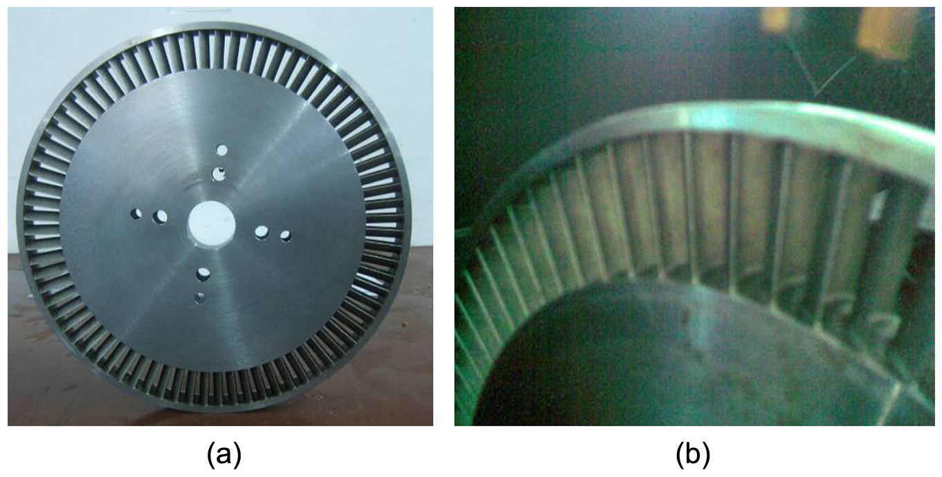
Rimmed turbine blisk: (a) rimmed turbine blisk; (b) blades of the blisk.
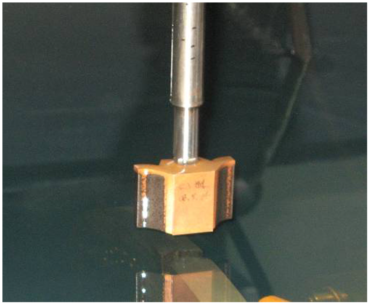
Tool electrode.
The blades of the turbine blisk should meet the following requirements:
The profile error range should be ±0.05 mm.
The error range of the radial dimension should be ±0.05 mm.
The shape of all the blades must be in high concordance.
The centerline must pass through the center of the turbine blisk and the error range should be±0.3 mm.
The error range of the central angles of the adjacent blades should be ±5′ and the error range of the central angles of all the blades should be ±12′.
The tool electrode must have a high shape accuracy because the shape accuracy requirement of the blades is very high and the blades are machined through shape-copying with a tool electrode. Otherwise, the inaccurate shape of the tool electrode can lead to an inaccurate machining gap distance that, in turn, leads to an inaccurate shape of blades. Furthermore, the initial position of the tool electrode must be accurate owing to the extremely high positional accuracy requirement of the blades.
The working surfaces of the tool electrode are especially designed according to the shape of the blade; thus, the tool electrode should also have a free-form surface with a complex shape and acutely changing curvatures. Current precision evaluation of a complex surface usually adopts digital measurement. Digital measurement is carried out by extracting the point cloud data of the surface and then calculating the error by numerical analysis (An et al., 2013; Choi and Kurfess, 1999; Yan et al., 1999; Yau, 1999). The main measurement modes are contacting and contactless (Ji, 2008; Ping et al., 2005; Zhang, 2006). The most common contacting measuring instrument is a coordinate measuring machine (CMM) (Ping et al., 2005), whereas the most common contactless measuring equipment are laser scanners and digital radiography systems (Zhuang et al., 2015). In addition, in the field of non-traditional machining, contact sensing technology is often used in carrying out measurements. In previous studies, the authors used this technology for the rough measurement of blades (Wu et al., 2003). However, these measuring methods are time consuming, costly and must be conducted in a designated place because of the high environmental requirement; as a result, production sampling of tool electrodes has to be adopted. However, not only is production sampling inconvenient, it also leads to the omission of unqualified tool electrodes and introduces some risks.
Usually, the initial position of the tool electrode is adjusted by the worker with a dial indicator on the machining equipment. During the process of adjustment, machining has to be stopped. This practice wastes considerable machining time and significantly reduces the production efficiency. For example, for a disk with 94 blades, every blade must be machined with four kinds of tool electrodes (Li, 2010). Moreover, the tool electrode can be used for machining five blades on average, the tool electrodes have to be changed and adjusted 76 times during the entire machining procedure, and the total unproductive time reaches up to 38 h under ideal conditions (Li, 2010). Some unpredictable man-made factors may also result in longer unproductive time.
Thus, it is particularly urgent to develop a measuring and presetting system for tool electrodes. With this system, the measuring and presetting can be accomplished successively on the same device. While machining is ongoing, the shape accuracy of the new tool electrode that will be used subsequently can be measured easily, quickly, conveniently and at a lower cost. Furthermore, the initial position of the tool electrode can be preset. When the old tool electrode has to be replaced, the new tool electrode can be installed on the machine tool directly and the machining can continue immediately.
Data-sampling method based on voltage monitoring
This entire work is founded on the data sampling method, which can realize the measuring demands mentioned in the previous section. The data-sampling method based on voltage monitoring is established while considering that the tool electrode is made of metal (usually copper) and it is electrically conductive. The sampling circuit is shown in Figure 3 (Lu et al., 2009).
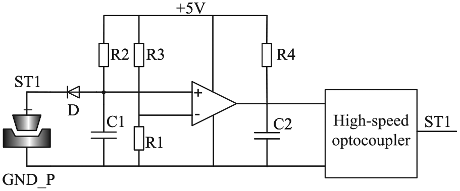
Data sampling circuit.
The probe and tool electrode are installed in the two poles separately. The voltage between them is inputted as a measuring voltage into the in-phase input terminal of the voltage comparator and 5 V of direct voltage is inputted as reference voltage into the out-phase input terminal of the voltage comparator after division. The output terminal outputs of the voltage comparator are signalled into the interface card through a high-speed optocoupler. The sampling procedure is described here. First, the probe moves to the tool electrode. Then, when the probe and tool electrode arrive at the critical contact state, the measuring voltage drops suddenly, causing a change in the output signal of the voltage comparator. Finally, after receiving the change, the control system records the coordinate information of the contact point. With reasonable trajectory planning and sampling strategy, the geometric information of the tool electrode can be sampled easily and quickly. The theory behind this data-sampling method is not complex; hence, it can be realized easily and at a lower cost.
Realization of the system
The measuring and presetting system of the tool electrode is developed based on the theory of the data sampling method. In addition, it is designed in accordance with the specific working conditions of the tool electrode and follows the principle of minimalist design, as shown in Figures 4 and 5 (Chen et al., 2013).
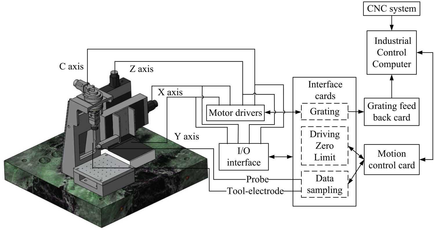
Measuring and presetting system for the tool electrode.
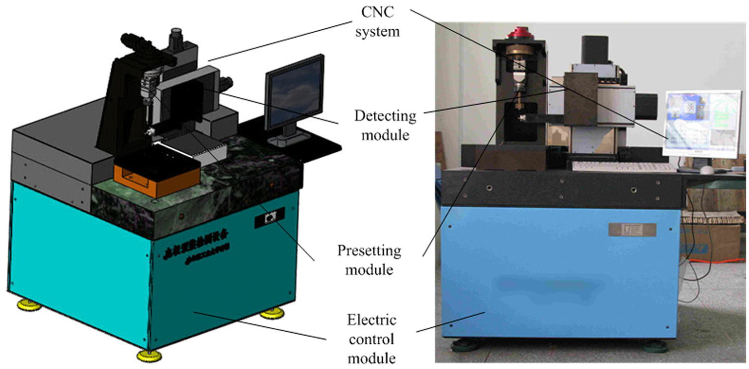
Solid figure and photo of the system.
The system consists of three parts: mechanical, electric control and computer numerical control (CNC) system software. The system can be placed at the machining site of the rimmed turbine blisks. While machining is ongoing, with this system, the tool electrode to be used subsequently can be first measured to determine whether it is qualified; it is then preset. The system not only makes the entire measuring and presetting work convenient but also avoids the omission caused by production sampling. After presetting, the new tool electrode can be directly installed on the machine tool without readjustment and the machining can continue immediately. This process significantly reduces unproductive time.
Mechanical and electric control parts
The mechanical and electric control parts are the two closely related hardware parts of the system. Both parts can be divided into three modules: measuring module, presetting module and electric control module.
The measuring module mainly realizes the measuring function; it includes the linkage of four axes: the X-, Y- and Z-axes, which are the linear axes, and the C-axis, which is the rotating axis. As shown in Figures 4 and 5, the C-axis is installed on the left side and the presetting module is installed on the C-axis. The other three axes are installed on the right side and the probe is installed on the X-axis. During the measuring procedure, the C-axis drives the presetting module to rotate to adjust the pose of the tool electrode, while the other three axes drive the probe to approach the tool electrode and sample the geometric information of the tool electrode.
The presetting module mainly realizes the presetting function and assists the measuring module, as mentioned in the previous paragraph. The presetting module consists of two parts: standard system 3R fixture and pose-adjusting unit. The standard system 3R fixture is installed on the C-axis. This fixture is the same as that installed on the machine tool, so it can be used as the reference for presetting, and it is the foundation and basis for presetting. The 3D explosion model of the pose-adjusting unit is shown in Figure 6.
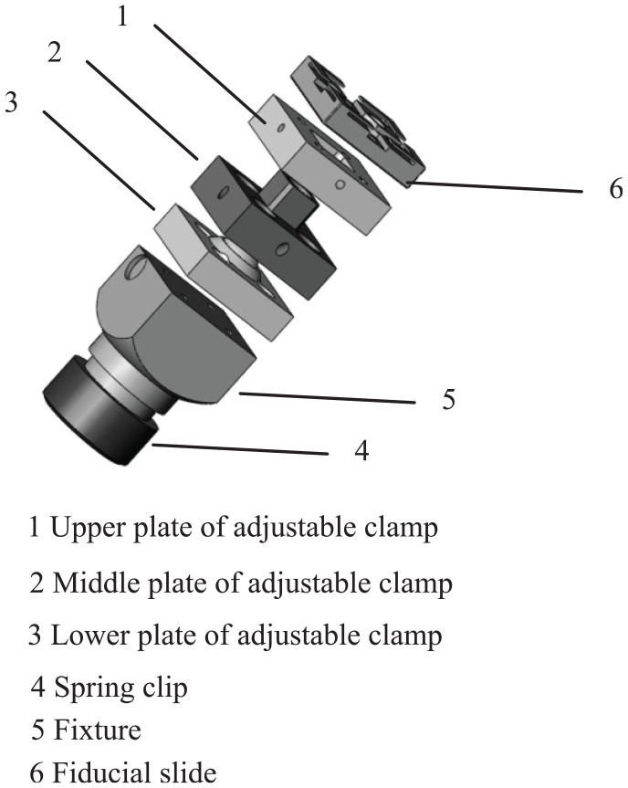
3D explosion model of the pose-adjusting unit.
The pose-adjusting unit mainly includes the upper, middle and lower plates of the adjustable clamp, the spring clip, fixture and fiducial slide. The tool electrode is installed on the fixture with a spring clip. The fiducial slide is fixed on the standard system 3R fixture to establish the location standard. All other adjustments are based on this location standard. The translational adjustment is realized through the large clearance fit between the middle plate and the lower plate of the adjustable clamp, whereas the angular adjustment is realized through the spherical fit between the upper plate and the middle plate of the adjustable clamp. When the old tool electrode has to be replaced, the new tool electrode that has been preset is installed together on the standard system 3R fixture of the machine tool, along with the pose-adjusting unit. The replaced pose-adjusting unit is used for the subsequent presetting work.
The electric control module serves as the connection between the other two modules and the CNC system software. The CNC system software controls the measuring and presetting modules to ensure that they perform their functions through the electric control module. An industrial control computer is used as the control platform and it runs the CNC system software. In turn, the CNC system software drives the servomotor to control the axis movement with the use of a motor driver and a motion control card, and then realizes an accurate control through grating feedback. The motion control card has a special part for realizing data sampling. With this part, the CNC system software monitors the status between the probe and the tool electrode, and performs data sampling at the right time.
CNC system software
The graphical user interface of the software is shown in Figure 7. The software has the functionalities for measuring and presetting the tool electrode, as well as other necessary assistive functionalities (Wang et al., 2006).
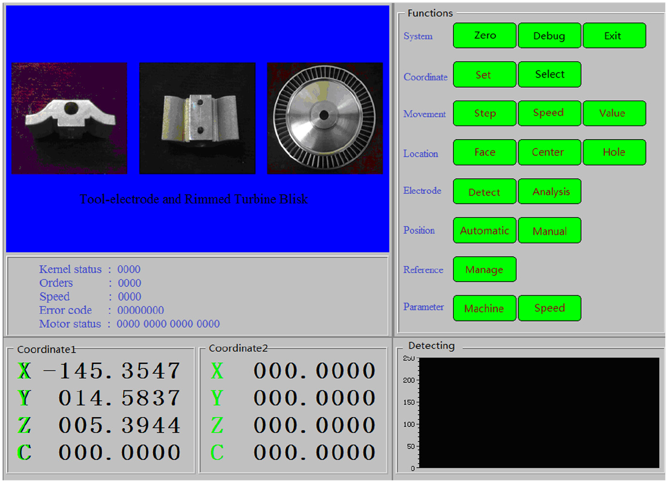
Graphical user interface of the software.
Figure 8 presents the flowchart of the measuring procedure. The measurement principle is explained here. First, the data-extracting coordinate system and measuring coordinate system are established according to the theoretical model of the tool electrode. Second, the theoretical geometric data of the characteristic points of the tool electrode are extracted from the theoretical model. Third, the measuring path is planned according to the theoretical geometric data (Ma et al., 2013; Wang et al., 2008), with these characteristic points as the target points. Fourth, the measuring module is driven to measure the actual geometric data of the characteristic points of the tool electrode. Fifth, the actual model of the tool electrode is reconstructed after processing the actual geometric data. Finally, the accuracy of the tool electrode is evaluated by comparing the actual model and the theoretical model.
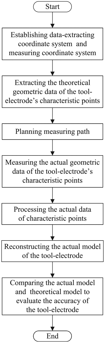
Flowchart of the measuring procedure.
Given that presetting is a simple application of measuring with the presetting module, the following sections mainly focus on the key parts of the measuring procedure.
Data of the characteristic points
Extracting the theoretical geometric data of the characteristic points
The data volume of the surface of the tool electrode is very large. Thus, the key to accomplishing rapid measurement is to establish a reasonable method to extract characteristic points from the theoretical model. Given that the working surfaces of the tool electrode are free-form surfaces, mesh generation is adopted and the grid nodes are extracted as characteristic points, following the common practice. The working surfaces of the tool electrode are designed specifically according to the shape of the blade. In addition, the blade adopts a hierarchical design; thus, the designed section lines of the blade are used as the section lines of the tool electrode. The quantity of sampling points on each section line is determined according to the empirical equation given by
where K is the technical ability factor related to design tolerance T and normal distribution
The geometric data of the characteristic points are extracted through the secondary development of the UG/Open. The data format is shown in Equation (2), which includes three coordinates and their direction cosines expressed as
where
Processing the actual geometric data of the characteristic points
The tool electrode has four working surfaces, which are free-form surfaces (Figure 2). Given that the probe is on the fixed side, the tool electrode has to rotate during the measuring procedure (Figures 4 and 5). As a result, the geometric data extracted from the four surfaces are not in the same coordinate system. Thus, these data must be converted into the initial coordinates. The transformation matrix is shown in Equation (3)
where
Reconstructing the actual tool electrode model
Bicubic B-spline surface interpolation is adopted for the reconstruction of the model (Sun et al., 2006). Here, the key is to obtain the control mesh through the reverse of topological rectangular data points. On the basis of the control mesh, the surface can be generated using a recursion method.
Bicubic B-spline curve reverse algorithm
The two endpoints of the curve should be
Given that a bicubic B-spline curve is adopted (k = 3), Equation (4) can thus be changed into
Substituting the nodes in the definitional domain of
The last equation can be changed into the matrix types given by
To be expressed and solved directly, Equation (7) can be changed into
In the equation,
All the unknown control vertices can be obtained by solving Equation (9) using a chasing method. Finally, the bicubic B-spline curve can be determined.
Bicubic B-spline surface reverse algorithm
The known data points
In the equation, the control curve is given by
The control vertices of the section curve
are expressed as
Given that the known data points
Simulation verification
A simulation analysis of the surface deviation was conducted to verify the reasonability and accuracy of the method for extracting the characteristic points of the tool electrode and the algorithm for the reconstruction of the actual model of the tool electrode. The verification must be done to compare the theoretical point cloud data of the tool electrode’s theoretical model and the interpolated point cloud data, based on the theoretical geometric data of the characteristic points with the reconstruction algorithms. The two kinds of point cloud data were imported into Imageware to reconstruct the corresponding surface and generate the deviation analysis figure and report. The report was imported into MATLAB to obtain the deviation distribution (Al-Araji, 2015; Lei et al., 2014). Figure 9 shows the deviation analysis and Figure 10 shows the deviation distribution of the four working surfaces of the tool electrode.
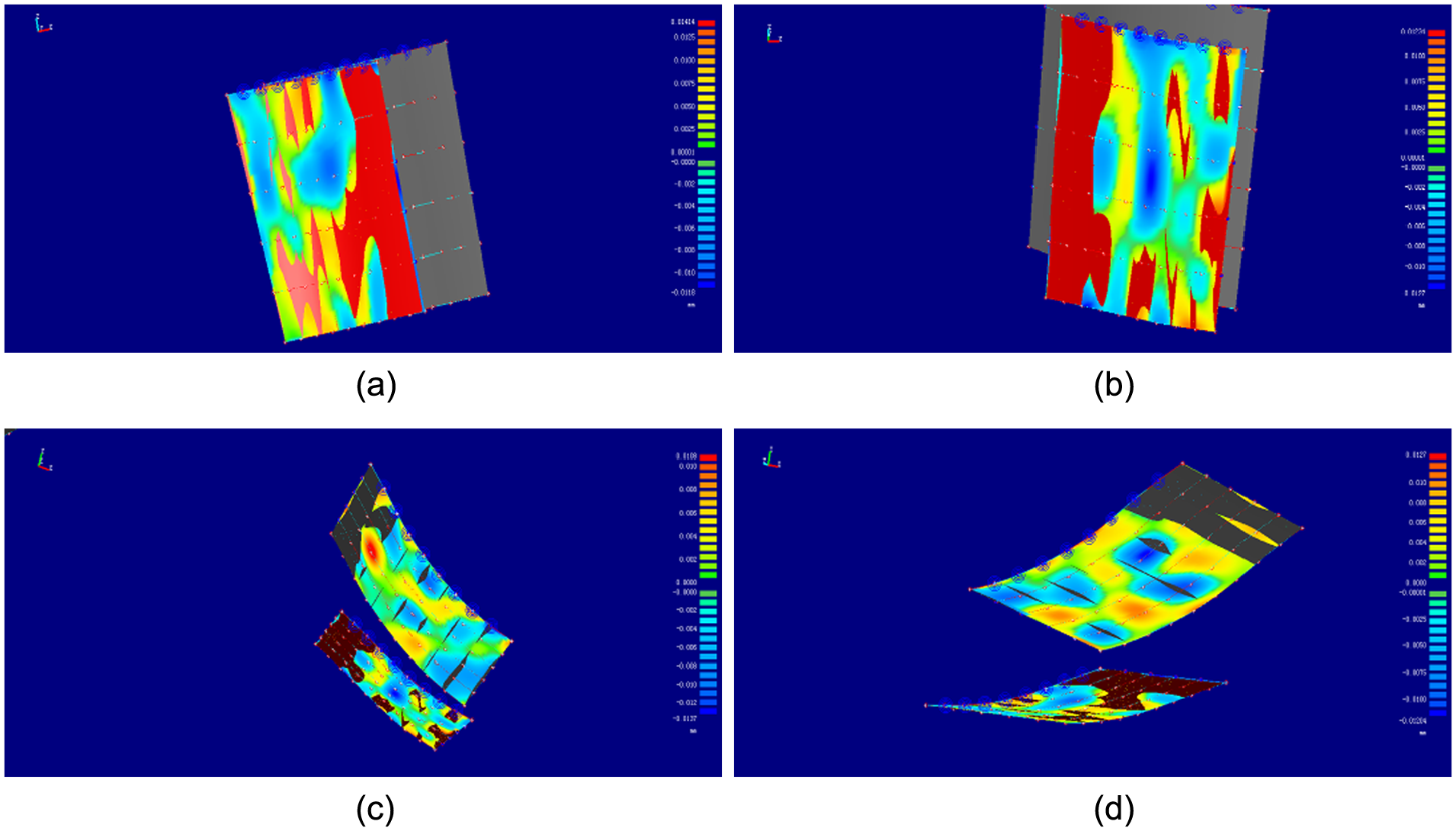
Deviation analysis figures of the four working surfaces of the tool electrodes: (a) no. 1 working surface; (b) no. 2 working surface; (c) no. 3 working surface; (d) no. 4 working surface.
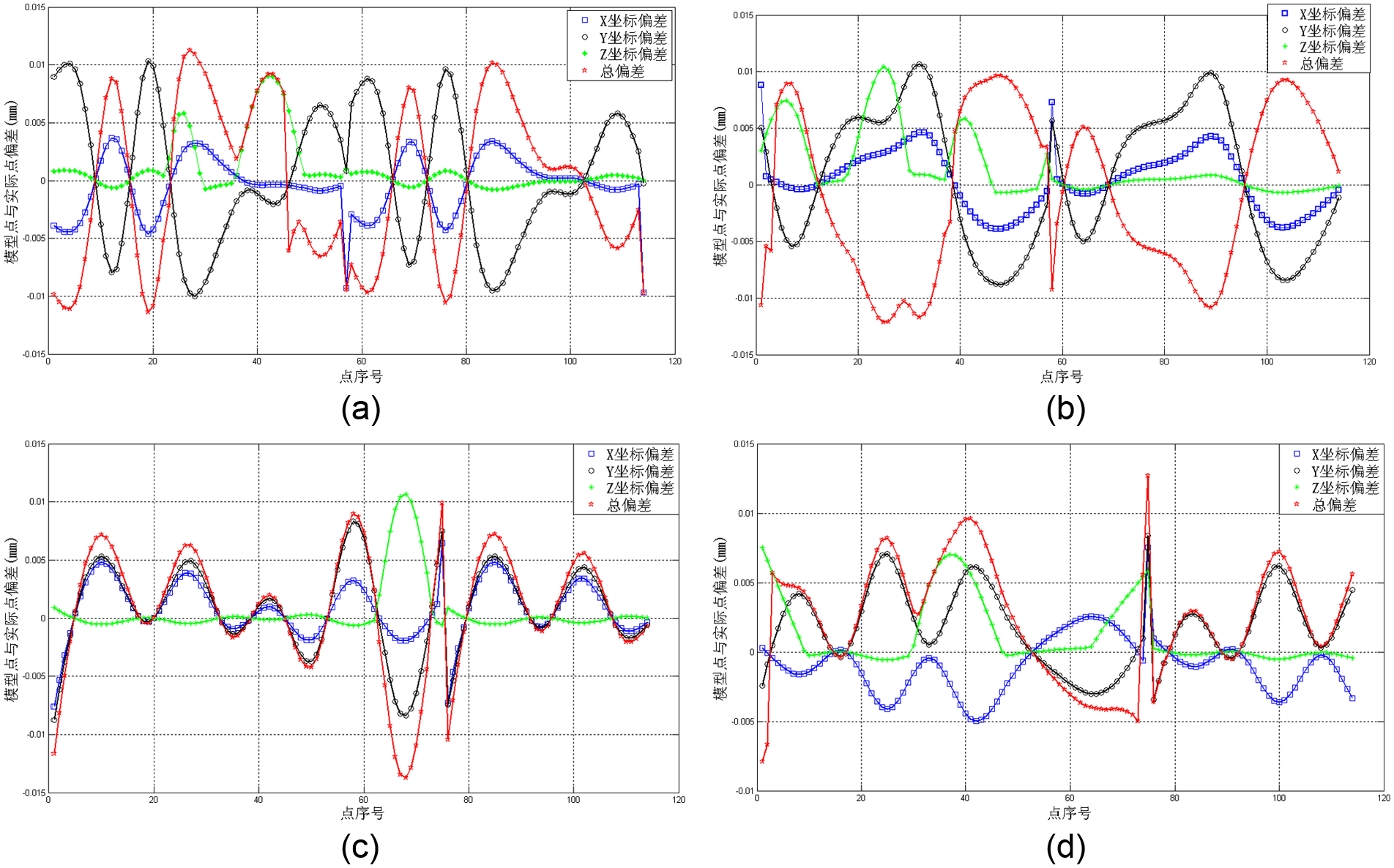
Deviation distributions of the four working surfaces of the tool electrodes: (a) no. 1 working surface; (b) no. 2 working surface; (c) no. 3 working surface; (d) no. 4 working surface.
Four lines are shown in Figure 10, each representing the deviations of the three coordinates and the total deviations of every point. The maximum total deviations of surfaces 1–4 are 0.01414, −0.0127, −0.0137 and 0.0123 mm, respectively. The reconstruction deviations satisfy the measuring requirement for the tool electrode.
Accuracy evaluation method of the tool electrode
A suitable accuracy evaluation method was established to evaluate the accuracy of the tool electrode. In the method, the intersection of the normal and actual surfaces of the theoretic point was first obtained and the deviation was subsequently obtained by calculating the distance between the theoretical point and the intersection. Given that
where M is assumed to be a theoretical point,
Equation (16) is the computational equation of intersection P. The equation is obviously the binary third-degree equation about u, v, and can be solved using a 2D optimization method. According to the characteristics of the B-spline fitting surface, the optimization of Equation (16) is non-restrictive and the parameter domain is linear.
Measuring experiments
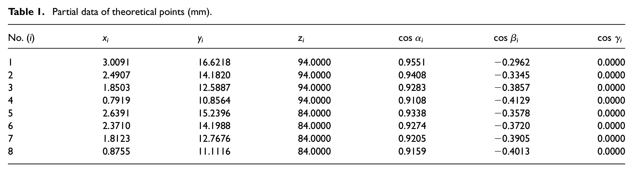
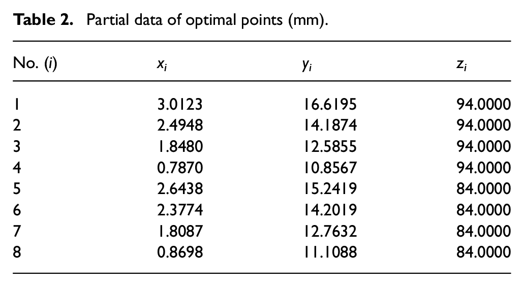
Several measuring experiments were conducted to verify the performance of the measuring and presetting system for the tool electrodes used for machining rimmed turbine blisks. Tables 1–3 present part of the experimental data at a certain time. Table 1 presents the partial data of the theoretical points, Table 2 presents the partial data of the optimal points and Table 3 presents the deviations. According the tolerance requirement, the shape accuracy of the tool electrode can be evaluated.
Partial data of theoretical points (mm).
Partial data of optimal points (mm).
Deviation of partial points (mm).
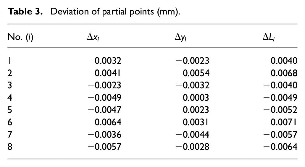
The experimental results can accurately reflect the actual shape accuracy of the tool electrode. At present, the system is applied to practical production and obtains satisfactory results.
Conclusion
In this paper, a data-sampling method based on voltage monitoring has been established. Based on the method, a measuring and presetting system for the tool electrodes that can be used for machining rimmed turbine blisks has been constructed. The application results show that the method is suitable and the design and accuracy of the measuring and presetting system are reasonable. With this system, measuring and presetting can be accomplished successively on the same device while machining is ongoing. This procedure not only makes the entire measuring and presetting work easy, quick and less expensive, it also significantly reduces unproductive time.
The method of extracting the characteristic points from the theoretical model of the tool electrode and the bicubic B-spline algorithms for reconstructing the actual model of the tool electrode has also been established. The simulation analysis results show that the reconstruction deviations satisfy the measuring requirement for the tool electrode.
A suitable accuracy evaluation method has also been developed to evaluate the accuracy of the tool electrode. Several experiments have been conducted. The experimental results show that the method and the system can achieve the actual shape condition of the tool electrode.
This study has practical significance and application value. Currently, the system is applied to practical production and has shown satisfactory results so far. If the cost of the system increases, our future work will focus on applying a manipulator to increase the accuracy and efficiency of the system.
Footnotes
Appendix
Conflict of Interest
The authors declare that there is no conflict of interest.
Funding
The author(s) disclosed receipt of the following financial support for the research, authorship, and/or publication of this article: This work was supported by the National High-tech. R&D Program, China, under Grant No. 2009AA044201.