






Abstract
For a bearingless motor that has two sets of stator windings, i.e. torque windings and suspension windings, the mutual inductance between the two sets of stator windings is a critical parameter; it is the basis of displacement sensorless control technology. Aiming at a three-phase bearingless motor, the equivalent two-phase mutual inductance model between two sets of stator windings is deduced. Then, based on the mutual inductance measurement method of a simple two-phase bearingless motor, a novel measurement algorithm of the equivalent two-phase mutual inductance is proposed, and the proposed measurement algorithm is applicable for a three-phase bearingless motor. Finally, based on a three-phase bearingless induction prototype motor, the experimental measurement of the equivalent two-phase mutual inductance is carried out. From the experimental results, it is clear that within the limited radial eccentricity of the rotor, the measured value of the equivalent two-phase mutual inductance is approximately proportional to the radial displacement of the rotor, and the correction coefficient kc of the equivalent two-phase mutual inductance model is derived; the consistency between measured and calculated values has verified the validities of the equivalent two-phase mutual inductance model and the proposed measurement algorithm from one instance. Thus, the theory foundation has been laid for research on the displacement sensorless vector control technology of a three-phase bearingless motor.
Keywords
Introduction
Conventional AC motors supported by mechanical bearings are widely used in various industrial fields (Sun et al., 2014a; Xin et al., 2016); its non-linear and intelligent control technology is being studied and applied systematically (Qiu et al., 2015, 2016). However, it is difficult to meet the requirement of long time and high speed operation; thus a motor supported by magnetic bearings has been developed (Chiba et al., 1994; Kim et al., 2014), but still has some disadvantages, such as higher cost of magnetic suspensions and limited critical speed (Bu et al., 2009; Huang et al., 2014; Sun et al., 2013a, 2014b). A bearingless motor is a new type of electric machinery proposed based on the comparability in structure between magnetic bearings and a conventional AC motor (Bu et al., 2009; Wang et al., 2012, 2015). With the study of the bearingless motor, a variety of bearingless motor structures have been developed (Bu et al., 2015; Chiba et al., 1994; Jia et al., 2014; Mitterhofer et al., 2015; Sun et al., 2013b; Wang et al., 2012). For most bearingless motors, there are two sets of stator windings, the number of pole pairs of which is different, include torque windings and suspension windings (Bu et al., 2009). Torque windings are the stator windings of the conventional AC motor, their number of pole pairs is P1 and their angular frequency of current is ω1. As for the suspension windings, their number of pole pairs is P2 and their angular frequency of current is ω2. When the suspension control magnetic field generated by suspension windings is superimposed on the rotating magnetic field of a conventional AC motor, the balance and symmetry of the air gap magnetic field is broken, the air gap magnetic field in some air gap area is enhanced and that in the space symmetric area is weakened; thus the resultant radial force is produced in the enhancement direction of air gap magnetic field. If the conditions P2=P1±1, ω2=ω1 are satisfied, the resultant radial force is controllable both in amplitude and in direction (Bu et al., 2009; Chiba et al., 1994). The controllable radial force is the so-called controllable magnetic suspension force; it can be used to counteract the inner unilateral magnetic pull and external radial load, and to achieve the stable suspension of the bearingless rotor. Compared with a motor with magnetic bearings, a bearingless motor has a series of advantages, such as shorter shaft, higher critical speed, etc. (Bu et al., 2009, 2014); the bearingless motor has become a research hotspot (Chiba and Santisteban, 2012; Wang et al., 2015). Figure 1 shows the generation principle of controllable magnetic suspension force. In Figure 1, Na and Nb represent four-pole torque windings, and Nα and Nβ represent two-pole suspension windings. On the moment when the current of stator windings is as shown in Figure 1, the controllable magnetic suspension force along the β direction can be generated. If the current direction of the suspension windings is reversed, the magnetic suspension force can be generated along the opposite β direction. The generation principle of magnetic suspension force along the α direction is similar.

Schematic diagram of generating controllable magnetic suspension force.
For a bearingless motor, the mutual inductance between the torque windings and suspension windings is a crucial parameter (Bu et al., 2009; Chiba et al., 1994). For example, the mutual inductance model between the two sets of stator windings is the theory basis of radial displacement self-sensing detection technology (Chiba and Santisteban, 2012; Tera et al., 2006). In addition, the ratio of mutual inductance to radial displacement is a key parameter in the controllable magnetic suspension force model. For different types of bearingless motor, there have been many studies on the controllable magnetic suspension force model and the decoupling control method (Bu, Zu and Lu, 2014, 2015; Hiromi et al., 2007; Jia et al., 2014; Wang et al., 2015). However, until now, there has been little research on the inductance model of a bearingless motor. Bearingless motors with a cylinder-type stator are classified into two basic types, i.e. bearingless motors with a salient-pole rotor, and those with a cylindrical rotor; the inductance model of a two-phase bearingless motor has been proposed by Chiba et al. (1994). Bu et al. (2009) normalizes the bearingless motor with a cylinder-type stator to a general structure and proposes a general inductance model of two-phase bearingless motor, thereby providing a way for research on the common principle of a bearingless motor. For a three-phase bearingless motor, with the change of radial displacement, the variation rule of mutual inductance between the torque windings and suspension windings is too complicated to be measured and used directly (Hiromi et al., 2007); but the mutual inductance model of the two-phase bearingless motor owns the characteristic of briefness (Bu et al., 2009; Chiba et al., 1994). In addition, the vector control technology has been widely used for AC motors (Bu et al., 2014), and the vector control has been achieved in an equivalent two-phase synchronous coordinate system. The equivalent two-phase mutual inductance model of a three-phase bearingless motor has higher practicality.
There is already a mature approach to the inductance parameter measurement of an ordinary three-phase AC motor, but the bearingless motor is a special AC motor, the pole pair number of torque windings is different from that of suspension windings, and the mutual inductance parameter between the two sets of windings varies with the radial displacement of the rotor (Bu et al., 2009; Chiba et al., 1994). In addition, the vector control technology of the bearingless motor may eventually enter the high power field, and the three-phase bearingless motor may be widely used in the future. Therefor, for an existing three-phase bearingless motor, how its equivalent two- phase mutual inductance between the torque windings and suspension windings may be measure is an urgent problem to solve. For a bearingless motor, only when reasonable measurement and calculation methods are adopted can the mutual inductance parameters be obtained accurately, and can the mutual inductance ratio coefficient M between the torque windings and suspension windings be further calculated. In this paper, the equivalent two-phase mutual inductance model of a three-phase bearingless motor is derived first. Then, according to the electromagnetism principle, a novel measurement algorithm of the equivalent two-phase mutual inductance of a three-phase bearingless motor is proposed. Finally, based on a three-phase bearingless prototype motor, the experimental measurement of the equivalent two-phase mutual inductance parameters and the experimental verification of the equivalent two-phase mutual inductance model are carried out.
Equivalent two-phase mutual inductance model of three-phase bearingless motor
For a two-phase bearingless motor, according to the relationship between magnetic flux linkage and current, the general mutual inductance matrix model between four-pole torque windings and two-pole suspension windings can be derived. The general mutual inductance model in an αβ stationary coordinate system and that in an xy rotor coordinate system can be expressed as follows (Bu et al., 2009):

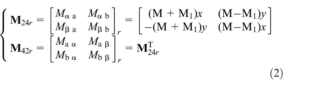
In (1) and (2), α and β are the radial displacement components in a stationary coordinate system; x and y are the radial displacement components in a rotor coordinate system; φ is the actual mechanical position angle of the salient pole on the rotor; M and M1 are mutual inductance ratio coefficients, and can be expressed as follows:
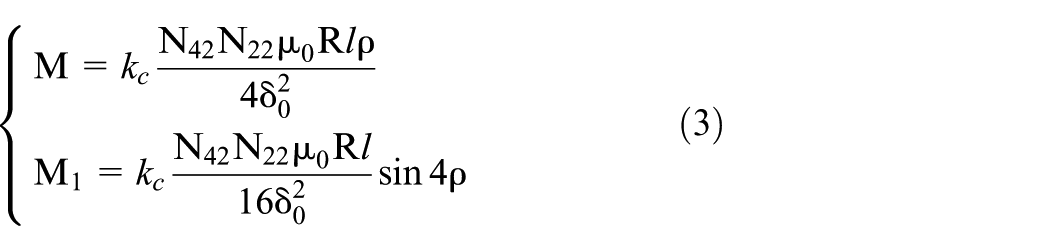
In (3), kc is a correction coefficient of mutual inductance and its value can be determined by mutual inductance experiment or finite element analysis; N42 is the effective turn number in series per phase of two-phase four-pole torque sine-windings; N22 is the effective turn number in series per phase of two-phase two-pole suspension sine-windings; μ0 is the magnetic permeability of air and μ0 equals 4π×10−7 H/m; ρ is an arc-width parameter, which is equal to one half of the arc-width of the salient pole on the rotor; R is the inner radius of stator; l is the length of iron core; and δ0 is the average air gap length of the bearingless motor on the unilateral side.
According to the vector coordinate transformation theory of AC motors, the relationships between the turn numbers in series per phase of three-phase bearingless motor and those of the equivalent two-phase bearingless motor can be expressed as follows:

In (4), N43 is the effective turn number in series per phase of three-phase four-pole torque sine-windings and N23 is the effective turn number in series per phase of three-phase two-pole suspension sine-windings.
Substituting (4) into (3), the equivalent two-phase mutual inductance radio coefficient of the three-phase bearingless motor can be derived as follows:
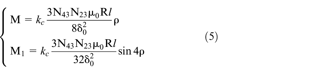
Equations (1), (2) and (5) constitute the equivalent two-phase mutual inductance model of the three-phase bearingless motor with a cylindrical stator, which is applicable for a bearingless motor with a cylinder-type stator, such as the bearingless induction motor, surface permanent magnet (SPM) bearingless motor and bearingless synchronous reluctance motor.
Based on the equivalent two-phase mutual inductance model and combined with the specific structural characteristics of the rotor, the equivalent two-phase mutual inductance model of a different type of three-phase bearingless motor can be derived. Taking the three-phase bearingless induction motor as an example, substituting ρ with π/4 in (5), following equations can be derived:
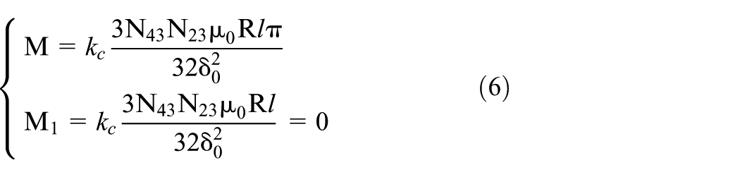
In (6), M and M1 are the equivalent two-phase mutual inductance ratio coefficients between four-pole torque windings and two-pole suspension windings of a three-phase bearingless induction motor, which are determined by the motor structure.
Then substituting (6) into (1) and (2), the following equations can be derived:
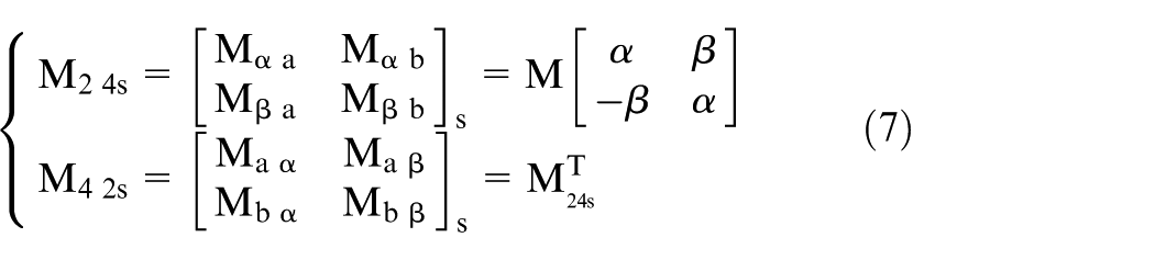
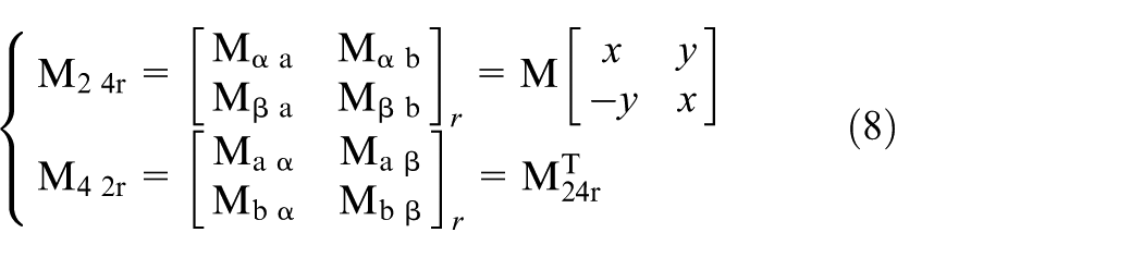
Equations (6), (7) and (8) constitute the equivalent two-phase mutual inductance model of a three-phase bearingless induction motor. From (6), (7) and (8), it is clear that for a three-phase bearingless induction motor, the equivalent two-phase mutual inductance model in the αβ coordinate system is similar to that in the xy coordinate system.
Measurement algorithm of the equivalent two-phase mutual inductance parameters of a three-phase bearingless motor
From the working principle of the bearingless motor, only when the rotor deviates from the stator centre can the electromagnetic coupling be generated between the torque windings and suspension windings. According to the electromagnetic coupling principle, the mutual inductance can be measured. Here, by exciting from line to line terminals, and by measuring from line to line terminals, the experimental measurement algorithm of the equivalent two-pole mutual inductance parameters of a three-phase bearingless induction motor is introduced.
Mutual inductance measurement method of two-phase bearingless motor
Figure 2 shows the mutual inductance measurement sketch map of a two-phase bearingless motor. The axis of four-pole a-phase torque windings is the same as that of two-pole α-phase suspension windings, and it is located on the stationary α coordinate axis.

Sketch map of mutual inductance measurement of a two-phase bearingless motor: (a) pulsant magnetomotive force production by single-phase four-pole torque windings; (b) Induced voltage measurement by single-phase two-pole suspension windings.
When exciting current is injected into torque windings, the produced two-phase four-pole magnetomotive forces can be expressed as follows:

In (9), N42 and N22 are the same as those in (3);
According to the working principle of the bearingless motor, when the bearingless rotor deviates from the stator centre, the electromagnetic coupling between the four-pole torque windings and the two-pole suspension windings comes into being, and the electromotive force in two-pole suspension windings is induced. Then, the analytical model of relevant mutual inductance parameters can be deduced as follows:
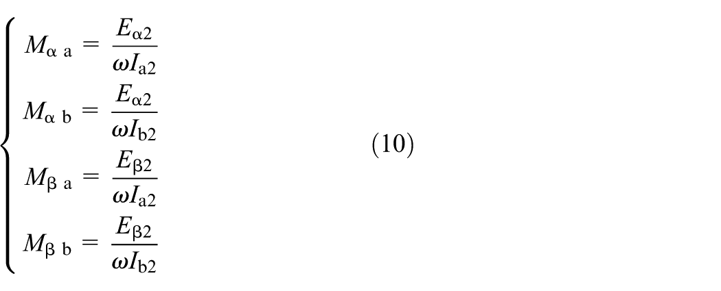
In (10),
Equivalent two-phase mutual inductance measurement algorithm of three-phase bearingless motor
Based on the three-phase bearingless prototype motor, the measurement algorithm of the equivalent two-phase mutual inductance between the three-phase four-pole torque windings and the three-phase two-pole suspension windings is deduced first; then by physical experiment, the variation rules of the equivalent two-phase mutual inductance parameters with the displacement are obtained, and the equivalent two-phase mutual inductance ratio coefficient is further corrected. The given measurement algorithm can be applied to the verification of the equivalent two-phase mutual inductance model; however, it can provide a theory and technology support for research on the displacement self-sensing detection based on the mutual inductance parameter variation.
Setting relationships between the relevant windings:
A1, B1 and C1 are the terminals of three-phase four-pole torque windings; A2, B2 and C2 are the terminals of three-phase two-pole suspension windings; ‘a’ and ‘b’ are the equivalent two-phase four-pole torque windings; ‘α’ and ‘β’ are the equivalent two-phase two-pole suspension windings.
The axis of A1-phase torque winding is in accordance with that of the equivalent a-phase torque windings; the axis of A2-phase suspension winding is in accordance with that of the equivalent α-phase suspension windings; the axis of a-phase torque winding is in accordance with that of the α-phase suspension winding.
When the equivalent two-phase mutual inductance are measured based on a three-phase bearingless induction motor, the magnetomotive forces along the axes of the equivalent a-phase and equivalent b-phase torque windings should be produced, and the inducted voltages or inducted electromotive forces along the axes of the equivalent α-phase and equivalent β-phase suspension windings should be measured.
Based on a three-phase bearingless induction motor, Figure 3 shows the production methods of the equivalent pulsant magnetomotive forces along the axes of the equivalent a-phase and equivalent b-phase torque windings. In Figure 3(a), B1-phase and C1-phase torque windings of three-phase bearingless motor are parallel connected, and the A1-phase torque winding is connected in series. Then a single-phase exciting current


Sketch map of producing equivalent two-phase pulsant magnetomotive force based on three-phase bearingless motor: (a) producing equivalent pulsant magnetomotive force along the axis of the equivalent a-phase torque windings; (b) producing equivalent pulsant magnetomotive force along the axis of the equivalent b-phase windings.
According to the connection method of windings presented in Figure 3(b), a single-phase exciting current

The magnetomotive force produced by the three-phase windings is equal to that produced by its equivalent two-phase windings:

According to (4), (9) and (13):

Under the same magnetic circuit conditions, when the exciting currents satisfy the qualifications in (14), then according to the windings connection presented in Figure 3, the same pulsant magnetomotive forces can be produced as those produced in Figure 2(a), and the same distributing of pulsant magnetic field can be achieved.
Figure 4 shows the measurement methods of the induced voltages of the equivalent two-phase suspension windings. In Figure 4(a), B2-phase suspension windings are parallel connected with the C2-phase, and then A2-phase suspension windings are connected in series. After the connections are completed, the inducted voltage along the axis of the equivalent α-phase suspension windings can be measured. According to the connection method of windings presented in Figure 4(a), the inducted voltage along the axis of the equivalent β-phase suspension windings can be measured.

Sketch map of measuring the induced voltage along the axes of the equivalent two-phase suspension windings of three-phase bearingless induction motor: (a) measuring the induced voltage along the axis of the equivalent α-phase windings; (b) measuring the induced voltage along the axis of the equivalent β-phase windings.
According to Figure 4:

Under the excitation of the magnetomotive force along α direction, the relationship between the induced electromotive force of the equivalent two-phase suspension windings and that of A2-windings in Figure 4(a) can be expressed as follows:

Under the excitation of magnetomotive force along the β direction, the relationship between the inducted electromotive force of the equivalent two-phase suspension windings and that of the B2-windings and C2-windings in Figure 4(a) can be expressed as follows:

According to (15)–(17):

According to (14), (18) and (10), the measurement algorithms of the equivalent two-phase mutual inductance of a three-phase bearingless motor can be derived as follows:

In (19),
From (19), it is clear that the proposed measurement algorithm has a series of advantages, such as simple connection of motor windings, smaller calculation amount, higher application efficiency and stronger practicability.
The practical application method can be concluded as follows: the radial displacement of the rotor along the α or β directions should be adjusted to an appropriate value first. Second, adopting the connection method of three-phase torque winding shown in Figure 3, a single-phase exciting current should be injected, and the required equivalent two-phase pulsating magnetic motive force can be generated. Then, according to the connection method of the three-phase suspension winding shown in Figure 4, the induced equivalent two-phase mutual inductance electromotive force can be measured. Finally, bringing the experimental data into (19), the equivalent two-phase mutual inductance parameter can be calculated. Under the conditions of different α or β radial displacement, multi-group mutual data can be directly measured and calculated, and the variation laws of mutual inductance parameters with α or β radial displacement can be directly drawn out. In addition, to avoid the obvious magnetic circuit saturation, the injected exciting current should be a little lower than its rated value.
Experiment and analysis of equivalent two-phase mutual inductance
Now, based on a three-phase bearingless induction prototype motor, the equivalent two-phase mutual inductance parameter is measured. As for SPM bearingless motor and bearingless synchronous reluctance motor, the experimental measurement method is similar and will not be described here.
The three-phase bearingless induction prototype motor is shown in Figure 5 and its parameters are as follows: four-pole torque windings: 2.2 kW, the rated voltage is equal to 120 V, N43 is equal to 204; two-pole suspension windings: the rated voltage is equal to 85 V, N23 is equal to 168; iron core dimension: R=62 mm, l=82 mm and δ0=0.6 mm.

Three-phase bearingless induction prototype motor.
Substituting the motor parameters into (6), the equivalent two-phase mutual inductance ratio coefficient can be derived as follows:

Then, (20), (7) and (8) constitute the mathematical model of the equivalent two-phase mutual inductance of the three-phase bearingless induction prototype motor.
To avoid the influence of induced current in rotor windings (Chiba and Santisteban, 2012; Tera et al., 2006), the iron core rotor without windings is adopted. During the experiment, in order to measure the mutual inductance parameters under different radial displacement, the radial displacement of the rotor needs to be adjusted according to an approximate equal span. Figure 6 shows the changing method of radial displacement.

Sketch map of experimental measurement device.
During the experiment, when the radial displacement of the rotor is set to a different value, the 50 Hz single-phase exciting currents ia3 and ib3 are in turn injected into the three-phase four-pole torque windings that are connected according to Figure 3; at the same time, the induced voltages of three-phase two-pole suspension windings are measured, and the suspension windings are connected according to Figure 4. After the experiment, the relevant data are processed according to (19). Then, under the conditions of different displacement, the experimental measurement values of the equivalent two-phase mutual inductance are calculated, and the actual change rules of the equivalent two-phase mutual inductance along with α and β displacements can be obtained. During the experiment, to avoid the influence of magnetic circuit saturation, the injected exciting current should be a little smaller than the rated value.
Figure 7 shows the change rules of the equivalent two-phase mutual inductance Mαa and Mβb along with α radial displacement. Figure 8 shows the change rules of the equivalent two-phase mutual inductance Mβa and Mαb along with β displacement. For the convenience of comparison, according to (7), (8) and (20), the model calculation curves of the equivalent two-phase mutual inductance are presented also. Here, the correction coefficient kc of mutual inductance is set to 1.0, i.e. the influences of the windings’ leakage flux and the iron core’s magnetic circuit pressure drop are ignored for a while.
From Figures 7 and 8, it is clear that:
Under conditions with no magnetic saturation and within the limited radial eccentricity of the rotor, the experimental measurement values of the equivalent two-phase mutual inductance between three-phase four-pole torque windings and three-phase two-pole suspension windings vary linearly along with α and β radial displacements; the linear change trend of experimental measurement value is in accordance with that of the model calculation value.
Under conditions with no magnetic saturation and within the limited radial eccentricity of the rotor, the average error between the experimental measurement value and the model calculation value is within 10%. The correction coefficient kc of mutual inductance is within the approximate range from 0.85 to 0.95, and the typical value of correction coefficient kc is about 0.9.
When the rotor’s radial eccentricity increases to a certain degree, the mutual inductance shows a non-linear enhancement trend along with α and β displacements.

Experimental results of the equivalent two-phase mutual inductance with the change of α displacement: (a) mutual inductance between equivalent a-phase torque windings and equivalent α-phase suspension winding; (b) mutual inductance between equivalent b-phase torque windings and equivalent β-phase suspension winding.

Experimental results of the equivalent two-phase mutual inductance with the change of β displacement: (a) mutual inductance between equivalent a-phase torque windings and equivalent β-phase suspension winding; (b) mutual inductance between equivalent b-phase torque windings and equivalent α-phase suspension winding.
The experimental process and results have shown the advantage characteristics of the proposed measurement algorithm in a further step, including smaller calculation amount, higher application efficiency, stronger practicability, etc.
Discussion and conclusions
In a common bearingless motor, there are two sets of stator windings with different numbers of pole pairs, i.e. torque windings and suspension windings. The mutual inductance between the two sets of stator windings is a crucial parameter; its change rule with the radial displacement of the rotor is the theory base of displacement sensorless control technology. However, for an existing three-phase bearingless motor, how its equivalent two-phase mutual inductance between the torque windings and suspension windings is measured is an urgent problem to solve. To meet the needs of displacement sensorless vector control of three-phase bearingless motors, the equivalent two-phase mutual inductance model between the torque windings and suspension windings, and the experimental measurement algorithm of the equivalent two-phase mutual inductance parameters of three-phase bearingless motor has been analysed in detail.
Based on the general mutual inductance model of a common two-phase bearingless motor (Bu et al, 2009), the equivalent two-phase mutual inductance model of three-phase bearingless motor is derived, and can be applicable for the bearingless induction motor, SPM bearingless motor and bearingless synchronous reluctance motor. Then an experimental measurement algorithm of the equivalent two-phase mutual inductance parameters of three-phase bearingless motor is proposed. Finally, based on an existing three-phase bearingless induction prototype motor, the proposed experimental measurement algorithm and the equivalent two-phase mutual inductance model have been verified and analysed.
According to the experimental results, there are following conclusions:
Under conditions with no magnetic saturation and within the limited radial eccentricity of the rotor, the experimental measurement values of the equivalent two-phase mutual inductance between two sets of stator windings vary linearly along with α and β displacements, i.e. the equivalent two-phase mutual inductance ratio coefficient is a constant. The average error between the experimental measurement value and the model calculation value is within 10%; the change trend of experimental measurement value is in accordance with that of the model calculation value.
The better accord between the measured mutual inductance value and the model calculation value has verified the validity of the proposed equivalent two-phase mutual inductance model of the three-phase bearingless motor and the validity of the proposed experimental measurement algorithm from one instance.
Under conditions with no magnetic saturation and within the limited radial eccentricity of the rotor, the correction coefficient kc of the equivalent two-phase mutual inductance model is within the approximate range 0.85–0.95; the typical value of correction coefficient kc is about 0.9. In actual applications, if the magnetic circuit appears a saturation phenomenon, a lower correction coefficient kc should be selected.
The equivalent two-phase mutual inductance model of three-phase bearingless motor, and the experimental measurement algorithm of the equivalent two-phase mutual inductance parameters have provide a theory and technology basis for research on the displacement sensorless vector control technology of the three-phase bearingless motor.
Analyses and discussions
Under conditions with no magnetic circuit saturation and within the limited radial eccentricity of the rotor, there is still about a 10% error between the measured value and the model calculation value of the equivalent two-phase mutual inductance. The causes that lead to the error mainly include leak magnetic flux of stator windings, neglected magnetomotive force down on magnetic circuit and the limitations of experimental conditions.
When the rotor’s radial eccentricity increases to some level, the mutual inductance presents non-linearly boosting along with α and β displacements, i.e. the equivalent two-phase mutual inductance ratio coefficient between the torque windings and suspension windings is not a constant again. This is caused by the badly lopsided distribution of the air gap magnetic field when the rotor deviates greatly from the stator centre. The result under this condition belongs to an extremity. However, in reliable operation of the bearingless motor, the displacements are far smaller than the average air gap length of motor and the rotor’s radial eccentricity is very much smaller. On the other hand, there is a mechanical bearing to meet an emergency in the bearingless motor; its average air gap is smaller than the average air gap of the motor. Thus, the present non-linearly boosting phenomenon of the equivalent two-phase mutual inductance with α and β displacements may not come into being in the actual operation of bearingless motor.
In practical applications, the motor parameter is unavoidably affected by temperature and magnetic circuit saturation. Whereas these factors are not considered in the presented equivalent two-phase mutual inductance model, it is a problem for further study.
Now, non-linear and intelligent control theory has been gradually applied to the high performance control of a common AC motor (Qiu et al., 2013a, 2013b). In order to realize the low cost and high performance control of the bearingless motor, based on the presented equivalent two-phase mutual inductance model and advanced control theories, research on non-linear prediction and compensation method of radial displacement, and that on intelligent control technology of bearingless motor, are all important tasks to complete.
Footnotes
Declaration of conflicting interest
The authors declare that there is no conflict of interest.
Funding
The author(s) disclosed receipt of the following financial support for the research, authorship, and/or publication of this article: The support of the National Natural Science Foundation of China (51277053), International Cooperation Project on Sci & Tech of Henan Province (114300510029) and Nature Science Fund of Henan Province Education Bureau (2010B510011) are acknowledged.