






Abstract
In this paper, position control is addressed for a two-joint robot finger system driven by pneumatic artificial muscles. It is hard to obtain high precision control for a two-joint robot finger system due to coupling and nonlinearities. A two-input and two-output decoupling problem is solved via active disturbance rejection control without complicated calculations. An extended state observer is designed to estimate the nonlinearities. Furthermore, the stability of the two-joint robot finger system is shown by a back-stepping method. Results from experiments are demonstrated to show the effectiveness of the proposed control approach.
Keywords
Introduction
Anthropomorphic pneumatic robots have drawn increasing attention in the biorobotic fields in recent years. Pneumatic artificial muscles (PAMs) are widely used as muscle-like actuators in hominine robotics due to their large output force-weight/force-volume ratio, high-tension force, long durability, low cost, cleanliness, and compliance (Ahn et al., 2007). There exists an obvious advantage for pneumatic actuators over rigid actuators when robots need to interact with human beings (Park et al., 2002; Shin et al., 2014). However, the compressibility of air and nonlinear elasticity of the rubber tube cause unwanted properties for PAMs, such as nonlinearities and time-varying behaviour (Chang et al., 2011). Hence, it is difficult to get a satisfactory control performance for a system driven by PAMs. Many control methods for systems actuated by PAMs have been designed recently. Some conventional proportion-integration-differentiation (PID) controllers are introduced for certain mechanisms driven by PAMs. A fuzzy self-tuning PID controller is designed to achieve desired dynamic performance targets under different conditions (Nuchkrua and Leephakpreeda, 2013). Moreover, a nonlinear PID controller based on neural networks is introduced for a 2-axes PAM manipulator to address the nonlinearities and time-varying problems in Thank and Ahn (2006). These controllers show a latent conflict between the fast nonlinear dynamics and the slow parameters updating, controllers give certain degrees of compensation for nonlinearities (Shen, 2010). Sliding mode control can guarantee the performance of trajectory tracking for a PAM driven joint system which is robust enough (Xing et al., 2010). A high order sliding mode controller is employed to assure the convergence of the electro-pneumatic systems (Girin et al., 2009). It is shown that sliding mode controllers guarantee a good transitional process and acceptable tracking accuracy, but it is hard to address the chattering in the tracking process (Zhang et al., 2007). Adaptive robust controllers are designed for unmeasurable uncertainties and disturbances (Zhu et al., 2008; Yang et al., 2014b). In Slotine and Li (1985), an adaptive controller is designed to deal with uncertain loads. An adaptive extended active observer is proposed to estimate the force and states in nonlinear robot systems (Chan et al., 2013). A robot arm system is convergent in finite time by adaptive control and sliding mode control methods (Malyuddin et al., 2014). An adaptive recurrent neural networks method is introduced to control the PAM manipulator under load varying situations (Ahn and Ahn, 2009). Controllers based on neural networks are good at fast learning, but they are limited by an inherent slow convergence rate. A decentralized single-input single-output (SISO) controller is introduced for a dexterous robot hand which is implemented in a sophisticated mechanism (Grossard et al., 2015). Therefore, to overcome the drawbacks of the aforementioned control methods, an active disturbance rejection controller is introduced in this paper.
Active disturbance rejection control (ADRC) technology was proposed by Jingqing Han in the late 1980s. A Tracking differentiator (TD), an extended state observer (ESO) and a nonlinear state error feedback controller (NSEFC) make up three main parts of the ADRC framework. There exist two properties in ADRC which are independence on the concrete model and strong anti-disturbance. Hence, it has been employed more and more for nonlinear control systems in recent years (Han, 1998, 2009). ADRC is applied in the fields of aeronautics and astronautics to tackle highly nonlinear, coupling, and uncertainty problems (Yang et al., 2016b). The ADRC approach tracks given input signals swiftly with reducing noise signals by TD (Xia et al., 2007). Severe uncertain nonlinearities are estimated by the ESO of the ADRC approach (Yang et al., 2015). The NSEFC realizes good static and dynamic performances of systems (Yang et al., 2014a). ADRC achieves a good control output performance for nonlinear disturbance problems and coupling problems. There is too much calculation involved when using a control method which needs a concrete system model. Note that ADRC is suitable to solve the multi-input and multi-output decoupling problem without too many complicated calculations. An ADRC controller shows its robustness for estimating and compensating uncertainties (Han, 2008). A nonlinear robust controller for horizontal motor-tendon driven joints and a PID controller for vertical cylinder-tendon driven joints are given in Beytullah et al. (2015) and Takahiro et al. (2005). To the best of our knowledge, there are few researches on two-joint robot finger driven by PAMs in a coupling power transmission way via ADRC, which motivates us to do this work.
In this paper, a two-joint robot finger system with a specific tendon transmission route driven by PAMs is designed. For the robot finger system with 2 degrees of freedom (DOFs), control shortcomings not only lie in the nonlinearities of PAMs but also lie in the unmodelled dynamics and coupling which is caused by tendon transmission route. That is, there exist severe uncertain nonlinearities in the two-joint robot finger system. An active disturbance rejection nonlinear controller is proposed based on a back-stepping method, which is used to solve the nonlinearities in the trajectory tracking process of the 2 DOF two-joint robot finger system. Some comparison results with this proposed method is presented in the experiment section.
Experiment setup and dynamical model
Experiment setup
In this paper, the research aims at emulating the movement of the distal index finger joint (DIFJ) and the proximal index finger joint (PIFJ) of the index finger, which is demonstrated in Figure 1.

Movement of the PIFJ and DIFJ.
Note that fingers are driven by muscles in the forearm via tendons, which is shown in Figure 2.

Anatomy of finger tendon.
Tendons are elastic tissues which connect the muscles and bones like a bridge. It has the tenacity to transmit large power. Some tendons are responsible for the extension of fingers, the other tendons control bending. In recent years, many biomechanically-designed robots’ dexterous hands have applied the tendon bionic principle, such as DIST hand (Caffaz and Cannata, 1998), it is demonstrated in Figure 3.

DIST dexterous hand.
The movement of the two joints is realized by two cables and four PAMs. In the two joint fingers, each joint is driven by a pair of artificial muscles and their cables. When the PAM diastoles, the cables will not diastole. To emulate the synergetic principle of agonist-antagonist muscles of a human being, an artificial muscle will inflate while another artificial muscle deflates in the same pair of actuators. If the joint needs to rotate counter clockwise, the PAMs need to deflate/inflate reversely as in the situation of clockwise. It doesn’t matter if the PAMs are inflated or deflated, the cables always are tensed. Hence, the cables are fixed on each joint by screws so that the cables can not skid on the joints. Figure 4 shows the diagrammatic drawing of the detail of a 2 DOF two-joint tendon driven finger actuated by four PAMs.

Detail diagram of a 2 DOF two-joint tendon driven finger.
A 3D model is established via SolidWorks software according to the principle of Figure 4, and an experiment setup is manufactured following the 3D model. The 3D model and manufactured setup are depicted in Figure 5.

Design and realization of two joint mechanism. (a) 3D design model. (b) Realization of 3D design.
The two-joint control experiment facility is depicted in Figure 6. Figure 6(a) demonstrates the work principle of Figure 6(b), which is a picture of the overall facility.

Principle and actual experiment setup. (a) Principle of the two joint system. (b) Two joint control experiment setup.
It realizes angle measure, control algorithm computation, and desired position tracking by PAMs and cables. Angles are measured by the optical-electricity encoders (OMRON, E6B2-CWZ3E 2000P/R. HENGXIANG, S18-J3N 1600P/R), a counting card (ADVANTECH, PCI-1784U) in the control computer (ADVANTECH, 610H) which receives the angle pulse signals sent by the encoders. Control signals are processed by the computer, sent from a D/A output card (ADVANTECH, PCL-726) to four electric proportional valves (SMC, ITV0050-3MS). These four electric proportional valves regulate the air pressure of the four related PAMs according to the control signals, then the PAMs will drive the joints to desired position.
Dynamic model
Based on Yang et al. (2014c) and Karayiannidis and Doulgeri (2012), the dynamic expression of the 2 DOF two-joint finger system is expressed as

where

in which

with

where

with


Details of executive mechanism.
Moreover,

with

Furthermore,

in which

where

where

where b denotes the length of wire mesh fibre, N is the winding number of the fibre,

where

where

where

where

Setting

and

where

where

The nonlinear function
Active disturbance rejection controller
An ADRC technique is proposed to control the angles of two joints to desired ones in this paper. The ADRC controller consists of a TD, an ESO, and a nonlinear controller based on a back-stepping method.
Tracking differentiator
In this paper, a continuous smooth signal and its differential signal are obtained by TD. This is a practical algorithm to mediate the conflict between rapidity and overshoot. A second order TD is designed for system (12). Which gives an error vector as follows

where

is the desired angle signal vector. The TD is expressed as follows

with

where

where
Extended state observer
In this section, an ESO is designed to deal with the nonlinear interior disturbance part of the 2 DOF two-joint finger system. The nonlinear term is extended as an extended system state, i.e.

where

The concrete expression of the extended state observer is written as follows

where

and

The concrete expression of function

where
ESO (18) is a vector expression which consists of two sub-ESOs. The two sub-ESOs share a similar expression structure. Only the convergence of one sub-ESO is needed to verify and the other sub-ESO is obtained in the same way. One sub-ESO state reconstructed error system is established based on ESO (18) and system (17). Let

where
Two functions are set based on the following state error reconstructed system as

where both
Given two regions

and two Lyapunov functions

To relax notation,

where

where

It is obtained that

The derivative of
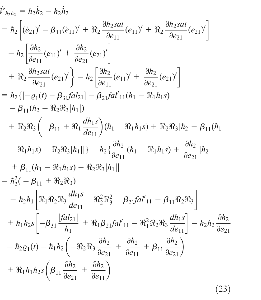
The derivative of the extended state

Choose parameters

and

holds.

A Lyapunov function

The derivative of the Lyapunov function
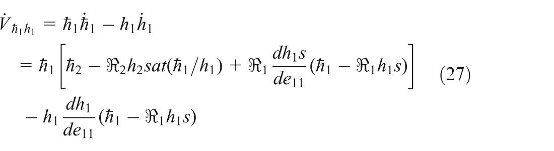
According to inequation (26),

There exists

Design a Lyapunov function

then the derivative of

There exist
Taking Theorems 1 to 4 into consideration comprehensively, no matter which region a trajectory belongs to initially, every error trajectory will converge to the origin directly, or it will be attracted by a certain region and go into it, or it will arrive to the utmost point after some time. It is obtained that
Nonlinear controller
In this paper, a nonlinear controller is designed to make the rotary movement of both joints of the robot finger track the desired angles precisely. The error variable system is shown as

where

with

Taking the derivative of the error variable system (31), it is rewritten as follows

The ADRC controller is designed as

where

The nonlinear controller (34) is substituted into system (33), the close-loop system is obtained as follows


Taking the derivative of the Lyapunov function

To relax notation,
Step 2: A Lyapunov function is given as follows

Taking the derivative of

Considering controller (34), there exists

where

with

where
Experiment results
In this section, some experiment results are given to demonstrate the performance of the proposed nonlinear controller under desired step signal. To show the executive mechanism, Figure 7 gives details on the facility.
Note that the experiment is carried out in a maximal air pressure 0.6Mpa, and the input-output function of the electrical proportional valve is expressed as follows

where P is the output air pressure(Mpa) and E is input voltage(v).
Firstly, the coupling effect is measured. One joint is controlled to track a step signal while the other one is under passive control, respectively. Coupling effect results are recorded in Figure 8. Figure 8(a) depicts the tracking result of the first joint when it is given a

Coupling effect of the two joints. (a) Joint 1’s tracking when Joint 2 is passive. (b) Joint 2’s tracking when Joint 2 is passive. (c) Joint 1’s tracking when Joint 1 is passive. (d) Joint 2’s tracking when Joint 1 is passive.
Set the step length h as 0.01. The gain matrix parameters for ESO are tuned by trial and error method, which are demonstrated as follows

The gains matrix of the controller

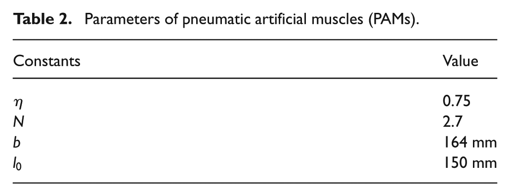
Other parameters with respect to the two-joint finger system are presented in Tables 1 and 2.
Parameters of the 2 DOF two-joint finger system.

Parameters of pneumatic artificial muscles (PAMs).
A step reference signal with

Comparison performance of two joints under two control methods. (a) Position tracking of the first joint. (b) Position tracking of the second joint.

Control signals of both control methods. (a) Control signals of ADRC method. (b) Control signals of PID method.
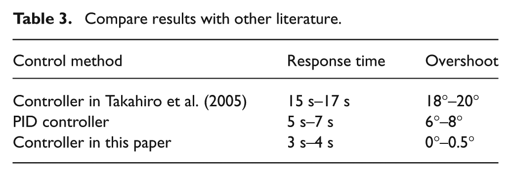
As shown in the Figure 9(b), there exists an overshoot of 6°–8° and a response time of 5 s–7 s by using the PID controller in the controlling joints. In contrast, ADRC controller can overcome the coupling effect in controlling the system, which is demonstrated from the low overshoot in Figure 9. A response time of 3 s–4 s and a steady error of
Compare results with other literature.
Conclusion
In this paper, an ADRC controller has been designed to study the position tracking problem of a 2 DOF two-joint coupling finger system which is actuated by PAMs. A desired trajectory has been tracked via TD with low overshoot by arranging transitional process. All state variables have been estimated via a designed ESO effectively. The close-loop control system is stable if the gain matrices are tuned large sufficiently, which is proved by a back-stepping method. Experiment results show the validity of proposed ADRC method. The response time of the close-loop system is 3 s – 4 s and the steady error is demonstrated as 0.02°.
Footnotes
Acknowledgements
The authors would like to thank the anonymous reviewers for their detailed comments which helped to improve the quality of the paper.
Funding
The author(s) disclosed receipt of the following financial support for the research, authorship, and/or publication of this article: The work of Ling Zhao was supported by National Natural Science Foundation of China (grant number 51505413) and the Hebei Provincial Natural Science Fund (grant number E2014203122). The work of Tao Wang was supported by National Natural Science Foundation of China (grant number 51375045).