
Abstract
This paper presents a pressure relief synchronous control method for four small entrapped high-pressure fluid volumes on a huge hydraulic machine. Firstly, as the existing pressure relief methods cannot behave well for small entrapped high-pressure fluid volumes, a novel electrohydraulic proportional pressure relief circuit is proposed. The electrohydraulic proportional pressure relief circuit is composed of a proportional pressure relief valve, a damping orifice and a constant pressure source, through which the pressure can be relieved proportionally to the command signal. Secondly, as the machine is a manned hydropower carrier, a very safety-critical application, a simple and easy to implement hybrid control scheme consisting of a synchronization controller and a pressure tracking controller is developed. As the pressure relief circuit has a wide range of operating conditions and parameter uncertainties, a practical self-tuning fuzzy proportion integration (PI) pressure tracking controller with feedforward is proposed, and a master–slave PI synchronization pressure controller with dead band is employed for the four entrapped fluid volumes. Finally, the experimental verification is implemented on a test stand to demonstrate the effectiveness of the proposed synchronous control system. The experimental results confirm that the pressure deviations among the four small entrapped high-pressure fluid volumes are bound within
Keywords
Introduction
A shiplift is a modern alternative for slipways, graving dry docks or floating dry docks. It can dramatically reduce the passing time for a ship through the dam.The wire rope hoist shiplift at the Wujiang River Sinlin hydropower station is designed to lift vessels with up to
When high-pressure oil rapidly discharges to a tank in a hydraulic system, there is a good chance of decompression shock. Decompression shock is one of the greatest types of damage to cylinders, piping and valves in hydraulic machines. The pipes and hoses can be broken and cylinder seals can be displaced by the energy released during decompression. Therefore, a pressure relief circuit can increase reliability and extend the hydraulic system’s service life (Wang et al., 2016). Prefill valves, triple-stage cartridge valves and electrohydraulic proportional cartridge valves are used in those pressure relief circuits. The existing proportional pressure relief circuits, usually used in large-scale hydraulic press machines, can relieve the high-pressure trapped fluid volumes in proportion to the given instructions (Ren, 2013). In fact, the high-pressure trapped fluid volumes on those large-scale hydraulic machines are usually bulky: for instance, the volume size is 584L on an 8000 ton thermoforming press (Chen, 2013). However, the size of the high-pressure trapped fluid volumes on the LDCs is approximately 1L. Because the bulk modulus of hydraulic oil is enormous (e.g.
The issue of synchronizing hydraulic actuators arises in many applications, and motion synchronization, pressure synchronization and velocity synchronization have found their applications in wider areas such as large-scale construction machines, hydraulic forming equipment, lifting equipment, multiple robot manipulator coordination, and so on. There is much literature on electrohydraulic position control and motion synchronization control, and various control algorithms have been proposed to achieve the desired synchronization and tracking accuracy (Chen et al., 2013; Xiao et al., 2012; Yao et al., 2015b). An independent linear and nonlinear motion synchronization control algorithm was proposed for the dual-cylinder electrohydraulic lift system, in which a nonlinear single input single output (SISO) perturbation-observer-based pressure-force controller was designed as the inner-loop controller for individual cylinder and a linear multiple input multiple output (MIMO) robust controller was designed as an outer-loop motion synchronization controller (Sun and Chiu, 2002). An integrated hybrid motion synchronization controller was presented for a dual-cylinder electrohydraulic system in the presence of unbalanced loading and uncertainties, which included a feedforward controller and a tracking fuzzy controller for an individual cylinder and a synchronous fuzzy controller to eliminate the motion synchronization error (Chen, 2007). A synchronization motion controller in a thrust hydraulic system of a shield tunnelling machine was achieved by compensating for displacement error using a master–slave PID with dead band (Yang et al., 2009). A hybrid control strategy was proposed to control a high-precision quad-cylinder electric-hydraulic levelling platform by a combination of fuzzy logic, sliding mode and PID MIMO techniques (Geranmehr et al., 2014). An integrated fuzzy controller was proposed to synchronize a primary flight control system, using a feedforward controller, an individual fuzzy position tracking controller and a fuzzy force coupled controller (Rehman et al., 2015). A digital sliding mode synchronization controller was presented to achieve the motion synchronization of several hydraulic cylinders, in which the state signals (position and velocity) of the previous cylinder and next one were employed for the proposed controller (Blagojević et al., 2015). An adaptive backstepping controller was proposed to improve the tracking performance in the presence of friction in hydraulic and mechanical engineering (Yao et al., 2015a). However, as the counterpart of hydraulic motion synchronization, hydraulic pressure synchronization has seldom been explored in the literature. Considering the parameter variations, outside disturbances and computer hardware conditions, a simple and practical fuzzy PI and feedforward hybrid control algorithm is adopted as the pressure tracking controller for individual actuators, and a master–slave PI controller with dead band is used as the pressure synchronization compensation controller, because of their simplicity and robustness.
Working principle of the proportional pressure relief circuit
As shown in Figure 1, the hydraulic circuit of each group cylinder on the LDC is made up of a pressure-reducing valve, a solenoid directional valve, a flow control valve, a counterbalance valve, two cylinders, a pressure sensor, a solenoid directional seat valve, a proportional pressure relief valve, a damping orifice, and so on. The function of the pressure-reducing valve is to supply a stable pressure source from the pump station; the solenoid directional valve and the flow control valve are used to control the direction and velocity of the cylinders respectively; and the counterbalance valve can balance the negative load and make the cylinders move smoothly. The proportional pressure relief circuit is composed of the proportional pressure relief valve, the solenoid directional seat valve, the damping orifice and the constant pressure source from the pressure-reducing valve. Before the proportional pressure relief circuit works, the solenoid directional valve and solenoid directional seat valve are de-energized. The high pressure in the piston chamber of the two cylinders is built up by the extra load. When the proportional pressure relief circuit begins to work, the solenoid directional seat valve and the proportional pressure relief valve are energized. The proportional pressure relief valve, the damping orifice and the constant pressure source constitute a B-type hydraulic semi-bridge, through which the pressure in the cylinder piston chamber can be relieved proportionally. The proportional pressure relief circuits on the four LDCs should work synchronously and keep the pressure deviations at less than
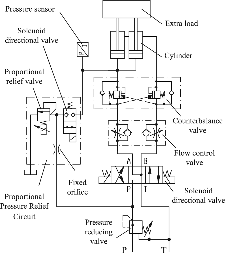
Schematic diagram of LDC hydraulic circuit.
Mathematical model of proportional pressure relief circuit
Figure 2 is a sketch of the analysed proportional pressure relief circuit. The pressure chamber, approximately
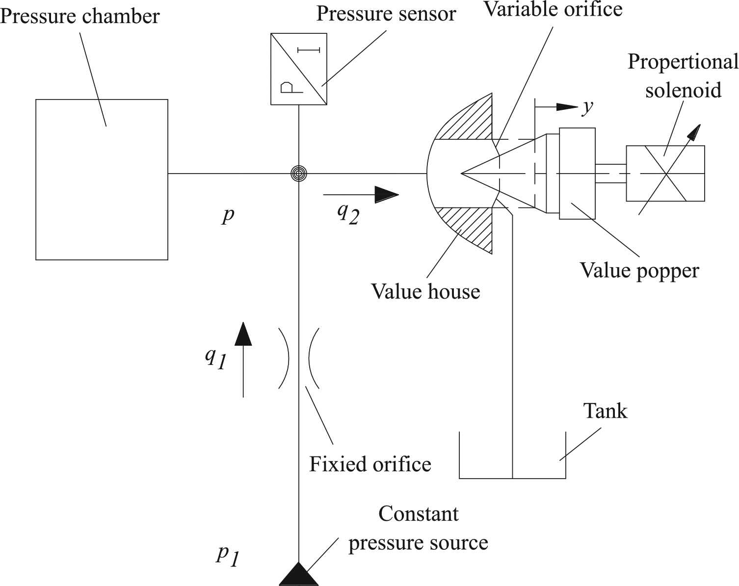
Sketch of the analysed proportional pressure relief system.
As shown in Figure 2, ignoring the leakage and volume change of the pressure chamber, when the continuity equation is applied to the pressure chamber it yields

where

where
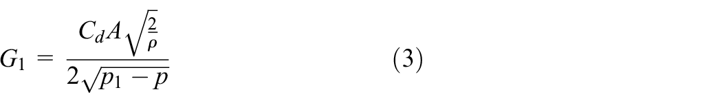
where
The valve poppet is subjected to pressure, jet reaction, spring force, viscous friction and electromagnetic force from the proportional solenoid. Its dynamic equation can be described by the following equation (Lu and Hu, 1988):

where
Based on equation (4), the dynamic mathematical model of the valve poppet is established using linearization and Laplace transform as
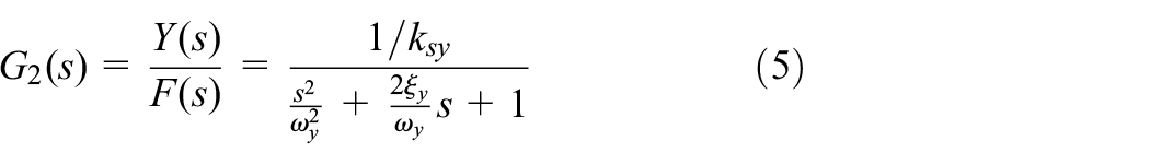
where
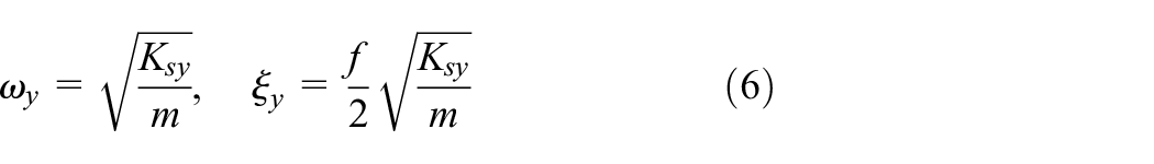
Equations (1) to (6) are the governing equations describing the pressure dynamic behaviour of the studied pressure chamber, through which the block diagram is obtained as shown in Figure 3.
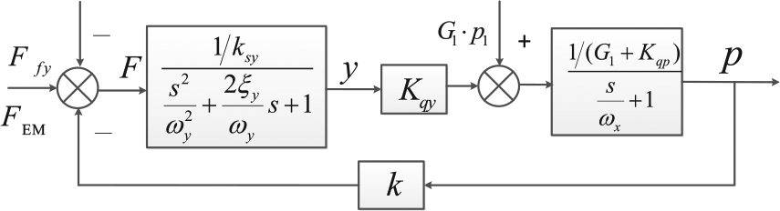
Control block diagram of the proportional pressure relief circuit.

Figure 3, equation (6) and equation (7) show that the dynamic characteristics of the pressure chamber are dominated by a second-order lag system and a first-order inertia system. The former reflects the dynamic characteristics of the proportional pressure relief valve, which is determined by the natural frequency of the industrial proportional pressure relief valve and can be found on its data sheet. The latter shows the resultant effect of the pressure volume, the proportional pressure relief valve and the fixed orifice, which is determined by these parameters: the flow-pressure coefficient of the fixed damping orifice
Controller design for the proportional pressure relief system
When the proportional pressure relief valve is used, it is found that nonlinearity appears due to the following three main factors (Gad, 2013).
The nonlinear change of the throttling area of the valve restriction.
The nonlinear velocity change of the fluid flow caused by the pressure change.
The discharge coefficient of the valve throttling area restriction does not remain unchanged.
Considering the uncertainty of system parameters and the nonlinearity in the hydraulic system, sufficient control accuracy cannot be guaranteed by the open-loop control mode for the proportional pressure relief valve control system. The influence of the various uncertainties on the performance of the pressure control must be attenuated by a closed-loop controller. To achieve acceptable control performance facing various uncertainties and constraints, different control algorithms have been proposed in some of the literature (Chen et al., 2016, 2015; Kumar et al., 2015; Sun et al., 2011, 2015; Yao et al., 2014; Yuan et al., 2017). As the shiplift is a manned hydropower carrier, a very safety-critical application, preference has to be given to simple controllers (Wang and Maré, 2014). A simple and easy to implement hybrid control scheme is developed in the literature.
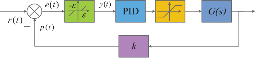
In most industrial PID controllers, the proportional gain
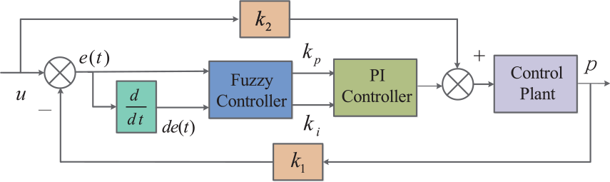
Block diagram of the self-tuning fuzzy PI controller with feedforward.
The complete fuzzy controller is composed of four components: fuzzification, knowledge base, inference engine and defuzzification. In the paper, there are two inputs for the fuzzy controller: pressure error


The knowledge base and inference engine include the input and output membership functions, the fuzzy control rules and so on. Here, let NB, NM, NS, ZE, PS, PM, PB, ZZ, SS, MM and BB all be triangular membership functions, and the membership functions of inputs and outputs are shown in Figure 5 and Figure 6. The fuzzy control rules contain information on how these inputs can be used to get new control actions. The experience and knowledge of an expert in a certain control field is usually used to make the knowledge base. In this paper, the fuzzy control rules have been chosen basing on how the PI controller parameters:
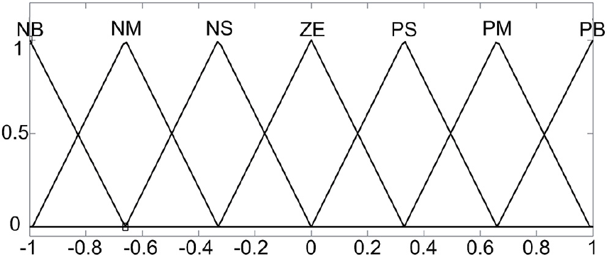
Membership functions for inputs.
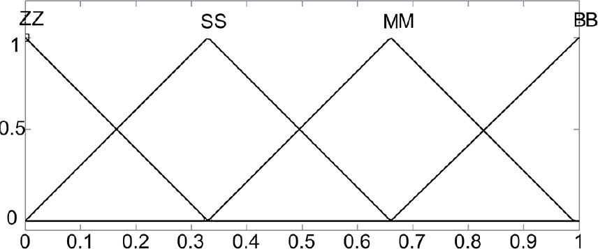
Membership functions for outputs.
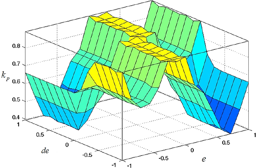
Three-dimensional view of the fuzzy rule
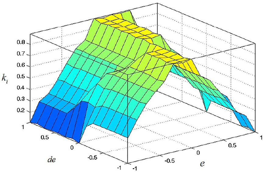
Three-dimensional view of the fuzzy rule
The designed synchronous pressure relief control system is controlled in four groups, and the pressure synchronous deviation between the four groups must be less than

where
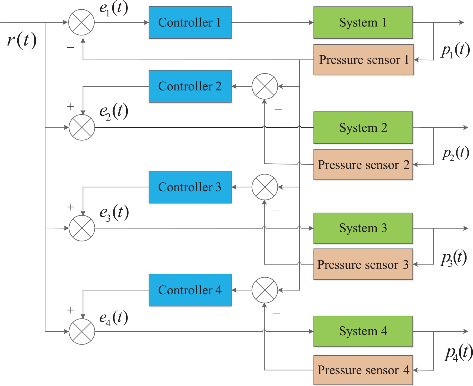
Block diagram of the synchronous proportional pressure relief circuit.
Block diagram of the PID with dead band.
Experimental results and discussions
As shown in Figure 11, the test stand mainly consists of a pump station, four proportional pressure relief valves, four pressure chambers, a data acquisition card and the Matlab/xPC control program. The pump station and proportional pressure relief valves are those used in the Wujiang Sinlin shiplift, and are shown in Figure 12. Four high-pressure hydraulic hoses are used as the trapped pressure chamber. A 16-bit national instruments (NI) data acquisition card 6229 is installed on a Yanhua industrial personal computer. The Matlab/xPC control program is finished in MATLAB R2014a. The list of main components used in the experiment system is shown in Table 1, and the list of main design parameters used in the experiment system is shown in Table 2.
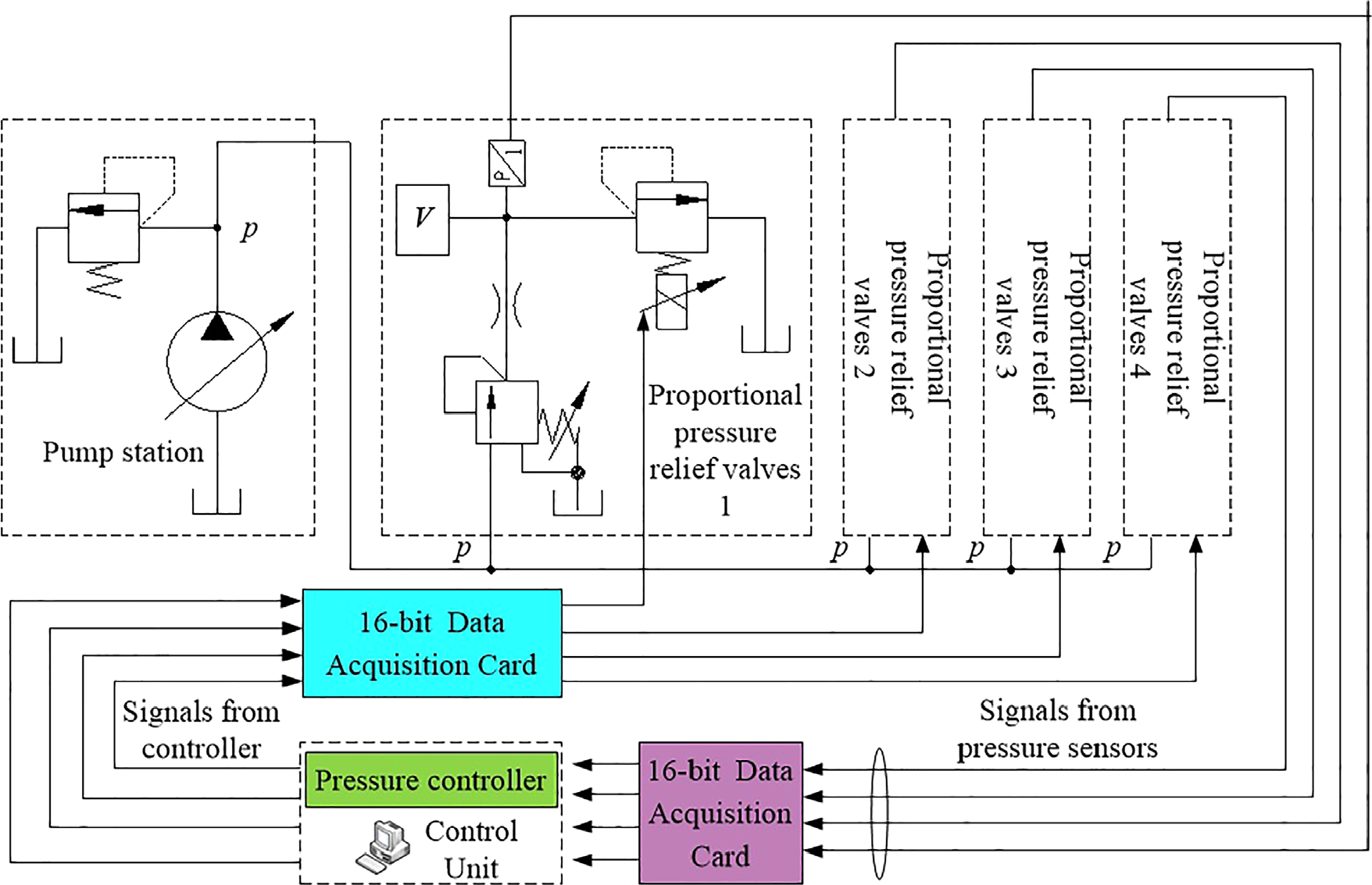
Structure of the test stand.
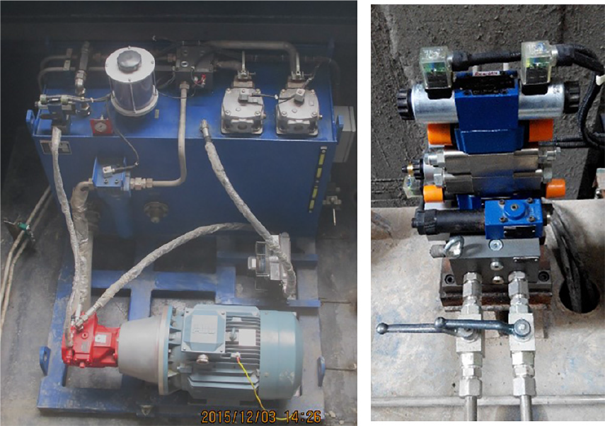
Pump station and proportional pressure relief valves.
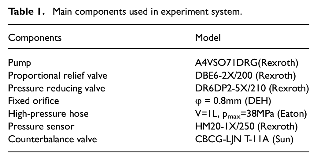
Main components used in experiment system.
Main design parameters used in experiment system.
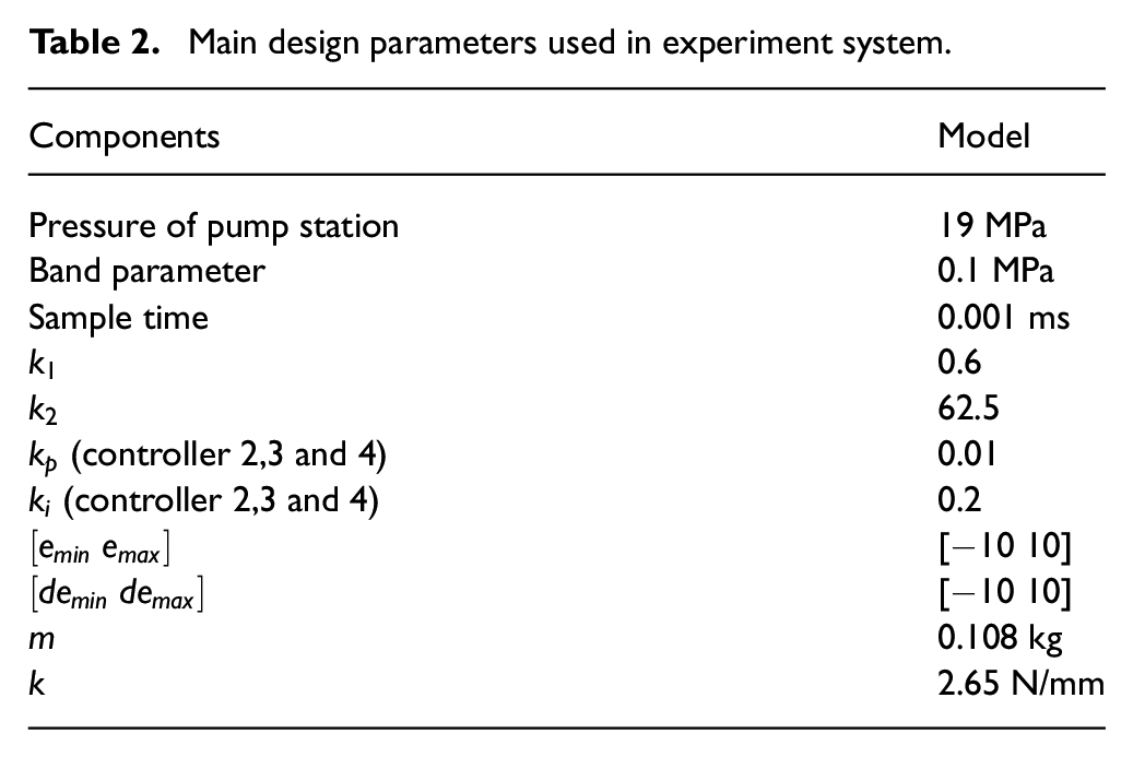
Figure 13 and Figure 14 show the synchronous pressure relief experimental results using the self-tuning fuzzy PI controller with feedforward when the proportional pressure relief circuits are actuated by a ramp wave voltage signal. It can be seen from Figure 13 that there were relatively larger pressure tracking deviations and lags between the command signal and the measured pressure curves at the beginning of the pressure relief process, but all the pressure synchronization deviations among the measured pressure curves are acceptable by using the designed control strategy. The pressure tracking deviations and the lags can be explained by the fact that the pressure control system can be approximately equivalent to a first-order inertia system, and the response of the pressure control system is almost inevitable with initial lag and error when the command signal is a ramp signal. This can be reduced by using a proportional pressure relief valve with faster response and a larger flow-pressure coefficient or a fixed orifice with a bigger flow-pressure coefficient. But a bigger fixed orifice will improve the minimum adjustable pressure of the pressure relief system. Because of the minimum adjustable pressure of the proportional pressure relief system, pressure below
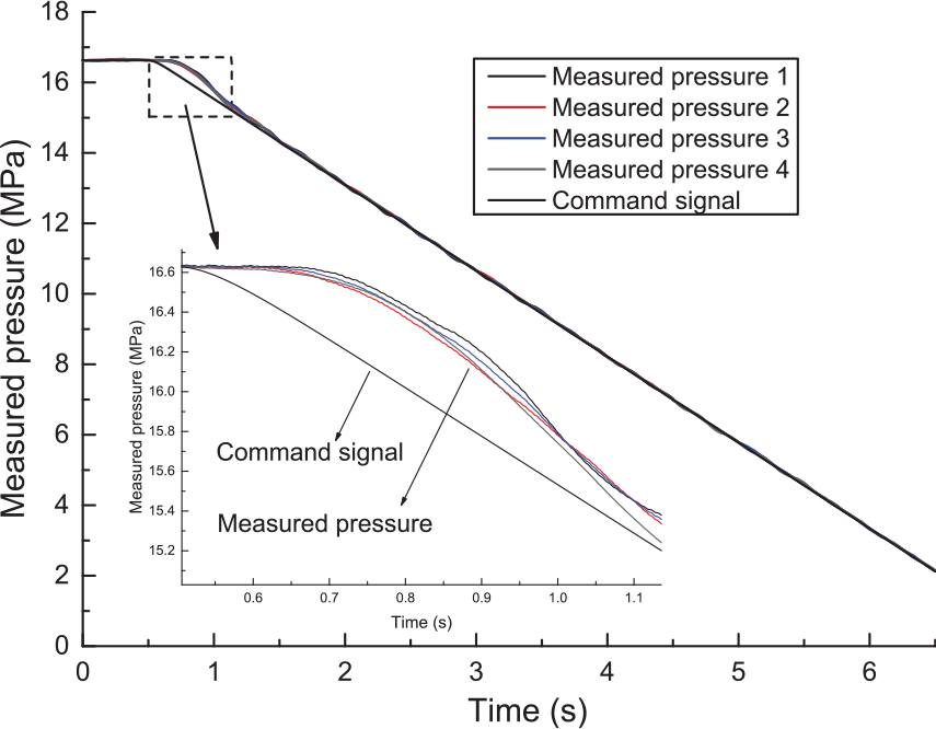
Measured synchronous pressure curves using self-tuning fuzzy PID with feedforward controller.
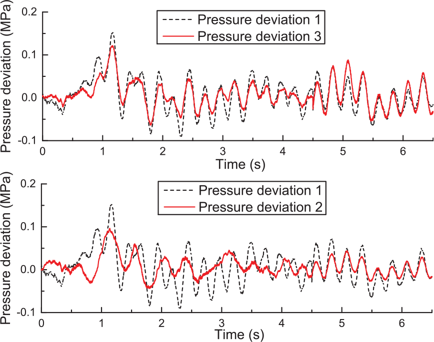
Measured pressure synchronous deviation curves of four pressure volumes.
The measured pressure synchronization deviations of four pressure volumes are shown in Figure 14. Pressure deviation
Figure 15 shows the synchronous pressure relief experimental results using a conventional PI controller with feedforward. It can be seen that there is a biggish pressure tracking error between the command signal and the measured pressure curves at the end of the pressure relief process, that is, when the command signal is smaller. One reason for this is that the fixed parameters of the conventional PI controller cannot guarantee better control quality when the system parameters vary. Figure 16 is the tested pressure curve when the used proportional pressure relief valve is actuated by a triangle wave voltage signal. It can be seen that the pressure-voltage gain of the proportional pressure relief valve can be divided into two stages: linear and nonlinear segments. When the command signal is smaller relatively speaking, the pressure-voltage gain becomes lower and nonlinear. The conventional PI controller with feedforward cannot guarantee the tracking error when the pressure-voltage gain of the proportional pressure relief valve varies. The self-tuning fuzzy PID controller with feedforward shows better robustness than the conventional PI controller with feedforward.
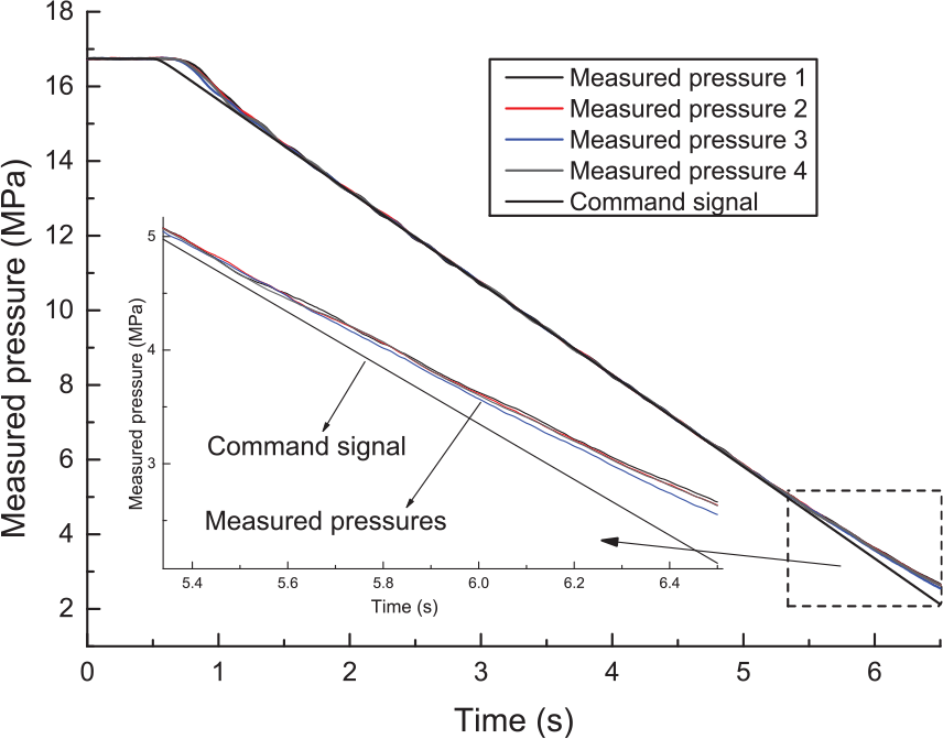
Measured synchronous pressure curves using PI with feedforward controller.
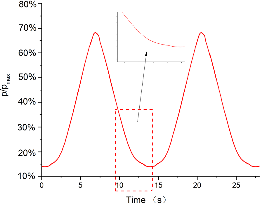
Measured characteristic curve of the proportional pressure relief valve.
Conclusions
A new electrohydraulic proportional pressure relief method is proposed in this paper for small trapped fluid volumes on four LDCs of the Wujiang Silin shiplift. The modelling and experimental results demonstrate the effectiveness of the proposed proportional pressure relief method. The proposed electrohydraulic proportional pressure relief method can also be used for small trapped fluid volumes in other equipment. To relieve the four small trapped fluid volumes synchronously, the self-tuning fuzzy PI controller with feedforward is used as the pressure tracking controller, and the master–slave PI controllers with dead band act as the pressure synchronization controllers. The robustness of the fuzzy PI controller is demonstrated by its good control performance through the whole operating range in comparison to a conventional PI controller. The experimental results indicate that the master-slave synchronization control strategy with dead band drawn lessons from motion synchronization can also conducted well in the pressure synchronization system.
Footnotes
Declaration of Conflicting Interests
The author(s) declared no potential conflicts of interest with respect to the research, authorship, and/or publication of this article.
Funding
The author(s) disclosed receipt of the following financial support for the research, authorship, and/or publication of this article: This work is supported by the National Key Technology Research and Development Program of the Ministry of Science and Technology of China (grant number 2015BAF07B06) and by the Anhui Province University Scientific Research Project (grant number KJ2017A058).