
Abstract
This article presents a novel control strategy on an electro-hydraulic shaking table under the acceleration control combining an amplitude phase controller and a zero phase error tracking controller with a discrete feed-forward compensator. Because of the electro-hydraulic system’s nonlinearity, phase delay and amplitude attenuation exist in the acceleration response signal inevitably when the electro-hydraulic shaking table system is excited by a sine vibration signal. Moreover, the phase delay of the electro-hydraulic shaking table is composed of phase deviation and actuator delay. For improving the acceleration tracking accuracy, an amplitude phase controller is employed to compensate the phase deviation and amplitude attenuation by introducing weights to adjust the reference signal. Meanwhile, the discrete feed-forward compensator is applied to compensate the actuator delay. As an offline compensator, the zero phase error tracking controller is employed to compensate the phase delay of the response signal and improve the convergence speed of the proposed controller. Overall, the proposed control strategy combines the merits of these three controllers with better tracking performance demonstrated by simulation and experimental results.
Keywords
Introduction
Electro-hydraulic shaking table (EHST), which is characterized by the simple structure, high precision, large bearing capacity and easy to control function, has been widely appplied to the industrial field as a essential equipment in the vibration mechanics testing (Shen et al., 2016a). When a vibration testing performs, the test specimen is fixed to the EHST and verifies the working performance with the simulative load applied by the testing system. It is generally known that the EHST has been extensively used to achieve seismic testing in earthquake engineering (see, for instance, Ghalibafian et al., 2004; Seven, 2011; Sanket and Sekhar, 2016). Also, shaking table was applied to damage diagnosis for conducting the measurement of structural mechanical impedance at high frequencies (Bhalla and Soh, 2003). In the civil engineering field, the dynamic displacement of railroad bridges under trainloads was measured in vibration testing utilized by a shaking table (Feng et al., 2015). For researching the effect of body force environment on the flat heat pipes, a shaking table was utilized to simulate vibration corresponding to aircraft maneuvering in frequency and amplitude (Zaghdoudi and Sarno, 2003).
However, the accurate reproduction of shaking tables can be affected by the uncertainty of the electro-hydraulic system, such as a couple of actuators, the intrinsic nonlinearity and the time variation (Wang et al., 2017). In the vibration testing, it is common that the acceleration response signal has the waveform distortion and higher harmonics. Although the traditional proportional-integral-derivative (PID) controller is one of the most important control strategies, the tracking performance is not satisfactory (Mo et al., 2017; Yakoub et al., 2017). Because of the time-varying feature of the EHST, an adaptive control methodology was applied for the vibration testing (Martynowicz, 2016; Shen et al., 2011, 2012). For example, Yao et al. (2015) proposed an adaptive backstepping controller to handle the parametric uncertainties of a hydraulic system. To extend the frequency bandwidth and improve the dynamic property, the inverse transfer function of the system was combined with a three-variable controller (TVC) and an offline feed-forward compensator (Shen et al., 2013). In order to obtain better tracking performance, Yao et al. (2014) proposed an extended-state-observer to track a desired signal trajectory, and Guo et al. (2016) combined an extended-state-observer with a backstepping controller to handle the load disturbance and uncertain nonlinearities. Though these control schemes above can get higher precision than a conventional PID controller, it is at the expense of structure complexity and calculation burden.
The shaking table here is under acceleration control with sine vibration, which is usually applied to simulate periodic motion in vibration testing. In the sine excitation experiments, the acceleration response signal is currently distorted by amplitude attenuation and phase delay caused by the nonlinearities of an electro-hydraulic system (Yao et al., 2016). The amplitude compensation depends on the value of the system gain, which is easy to implement in the engineering application. However, the phase compensation is relatively complex, and it is closedly related to the system design of hardware and software. The phase delay of the EHST is composed of phase deviation and actuator delay, in which the former is determined by the use of signal processing technology, such as the measuring principle and the controller design. The latter is caused by the time of the data transmission and sampled-data processing. Furthermore, a simple scheme, amplitude-phase regulation, was proposed to improve the phenomenon using a least mean square (LMS) adaptive filter, which made the output signal track the input efficiently (Yao et al., 2013). For minimizing the effect of the system delay, Chen and Ricles (2009) designed an actuator delay compensator in real time testing by using the discrete control theory. Based on the backstepping design method, an adaptive control scheme was investigated to compensate the time-varying delays (Hashemi et al., 2015). Furthermore, Jung and Shing (2006) utilized the discrete feed-forward compensator (DFC) to compensate the actuator delay, which presented an excellent performance. To compensate the time varying delays with uncertain processes, Norrney-Rico et al. (2012) proposed a discrete dead-time compensators on the basic of the Smith predictor. Besides, a discrete proportional resonant controller was employed to compensate the system delay (Shen et al., 2016b).
In order to minimize the phase delay and improve replication accuracy, this paper points out that the proposed controller combined with three controllers, including an amplitude phase controller (APC), the DFC and a zero phase error tracking controller (ZPETC), can improve the tracking performance of the EHST effectively. In addition, the APC is applied to compensate the phase deviation and amplitude attenuation of the acceleration response signal, and the DFC is applied to compensate the actuator delay. Either way, the ZPETC can not only achieve the offline phase compensation and improve the convergence speed of the proposed controller significantly. The rest of this paper is organized as follows. The dynamic model of the EHST is established in ‘Dynamic model of the electro-hydraulic shaking table’, and the proposed controller is designed in ‘Controller design’. Beyond that, the results and analysis of simulation and experimental are presented in ‘Simulation results and analysis’ and ‘Experimental setup and results’, respectively. Lastly, ‘Conclusion’ concludes the main points and contributions of this study.
Dynamic model of the electro-hydraulic shaking table
The shaking table here is a single degree of freedom system with two actuators, which are the double ended hydraulic actuators. Because the actuators are all controlled by the three-land-four-way servo valves with the same working principle, thus one of the actuator systems is studied here to set up the dynamic model. A simplified physical model of an electro-hydraulic system is shown in Figure 1.
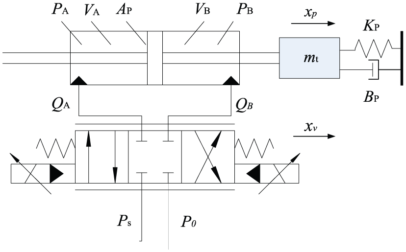
Simplified physical model of the electro-hydraulic shaking table.
The load flow QL can be expressed by

where xv is the spool displacement of the servo valve, PL is the load pressure across the load defined by
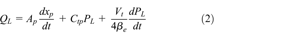
where Ap is the effective area of the cylinder, xp is the cylinder displacement, Ctp is the total leakage coefficient, Vt is the total chamber volume, βe is the oil effective bulk modulus. Ignoring the fluid mass and friction, the force balance equation can be obtained and the force exerted on the payload is expressed by (Liu et al., 2016)
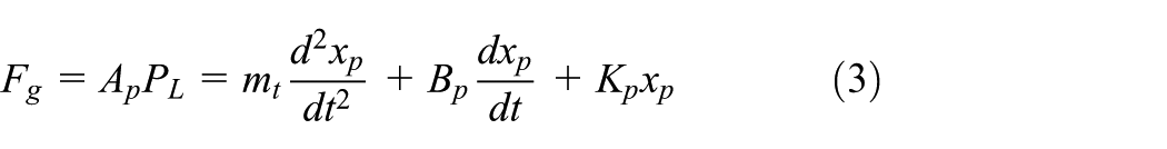
where mt is the total mass with respect to the piston, Bp is the viscous damping coefficient, Kp is the force spring coefficient. The transfer function of servo valve can be simplified by
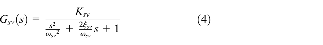
where
Employing Laplace transform to (1), (2) and (3), the open-loop transfer function from the spool displacement xv to the exerted force Fg can be expressed by
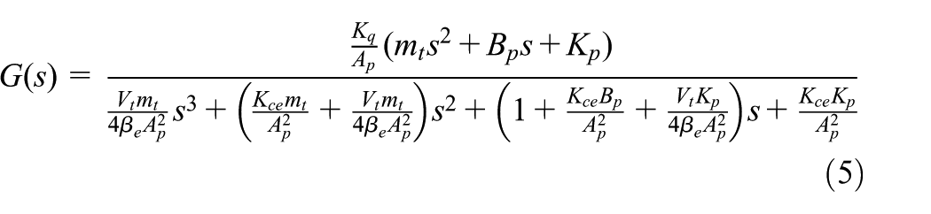
which can be further simplified by
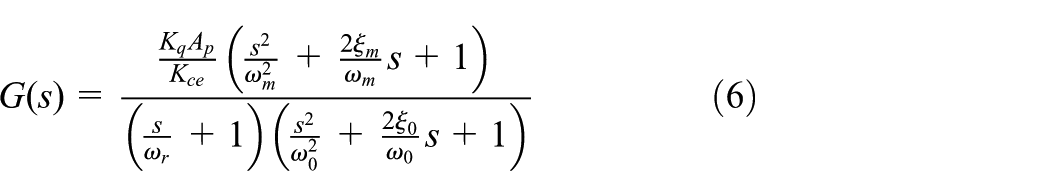
where
Controller design
As a kind of classic vibration form, sine is adopted in many kinds of periodic vibration testing. However, when a sine vibration testing performs, phase delay and amplitude attenuation exist in acceleration response signal. Thus, it is necessary to compensate the acceleration response signal to obtain better performance, so as to improve the tracking accuracy of the EHST. The phase delay

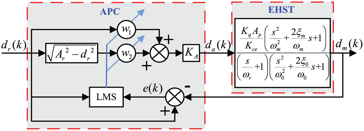
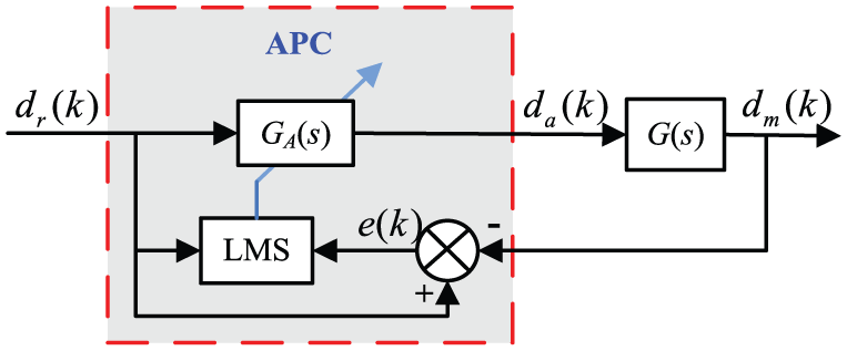
The proposed control strategy is shown in Figure 2, and the APC and the DFC are used to compensate the phase deviation
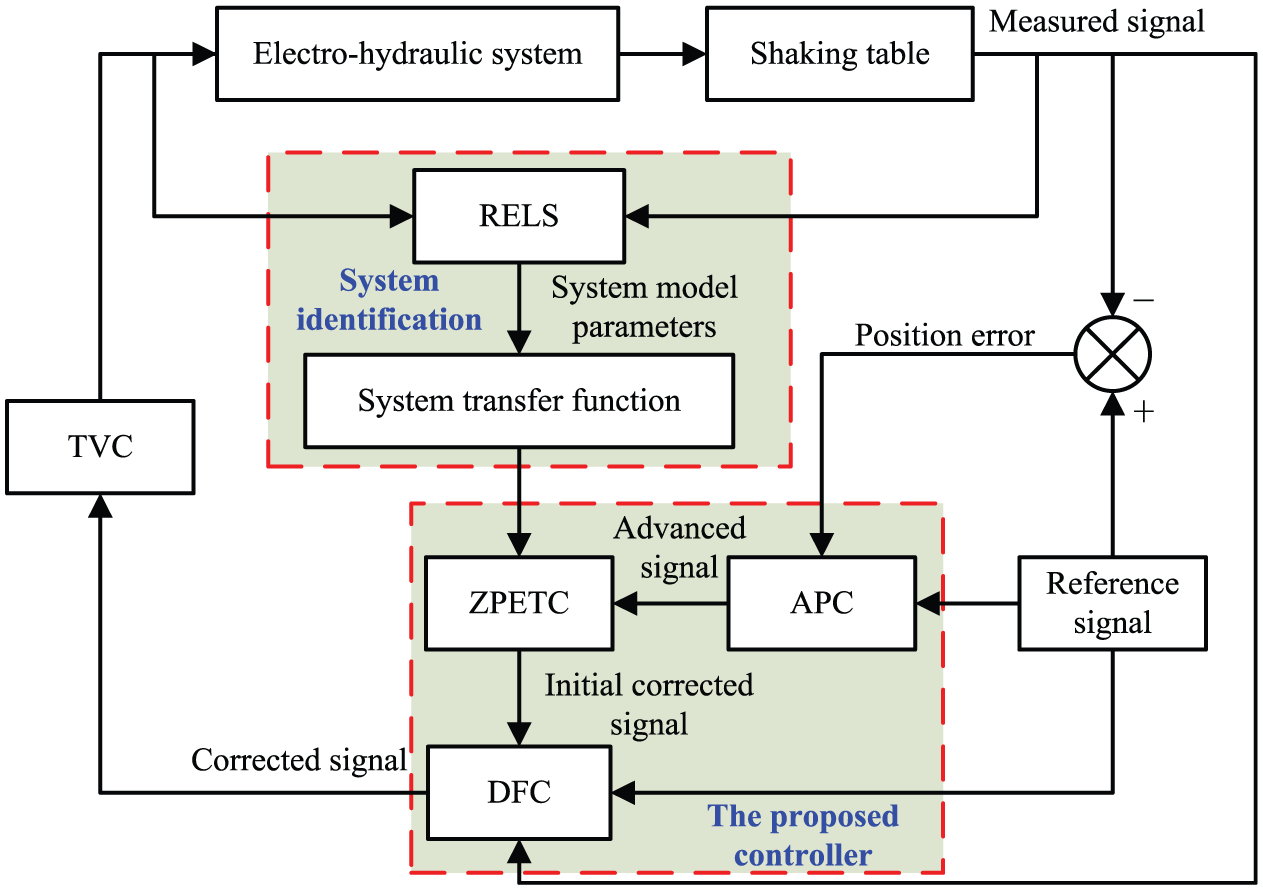
Block diagram of the proposed control strategy.
LMS algorithm
LMS, a kind of stochastic gradient algorithm, is widely employed with the simple structure, efficient computing and good performance (Zheng et al., 2016). The iterative equation is (Widrow et al., 1976)

where

is the output signal,

Define the weight error vector as

where

where
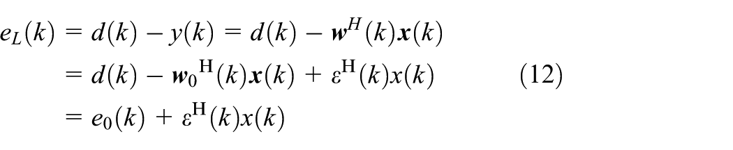
The corresponding cost function can be expressed by
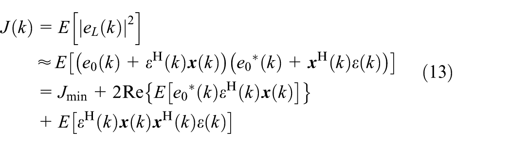
Because

and the following equation is based on the direct average method
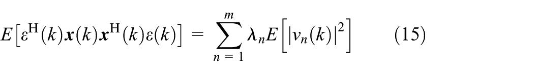
where
Substituting (14) and (15) into (13),
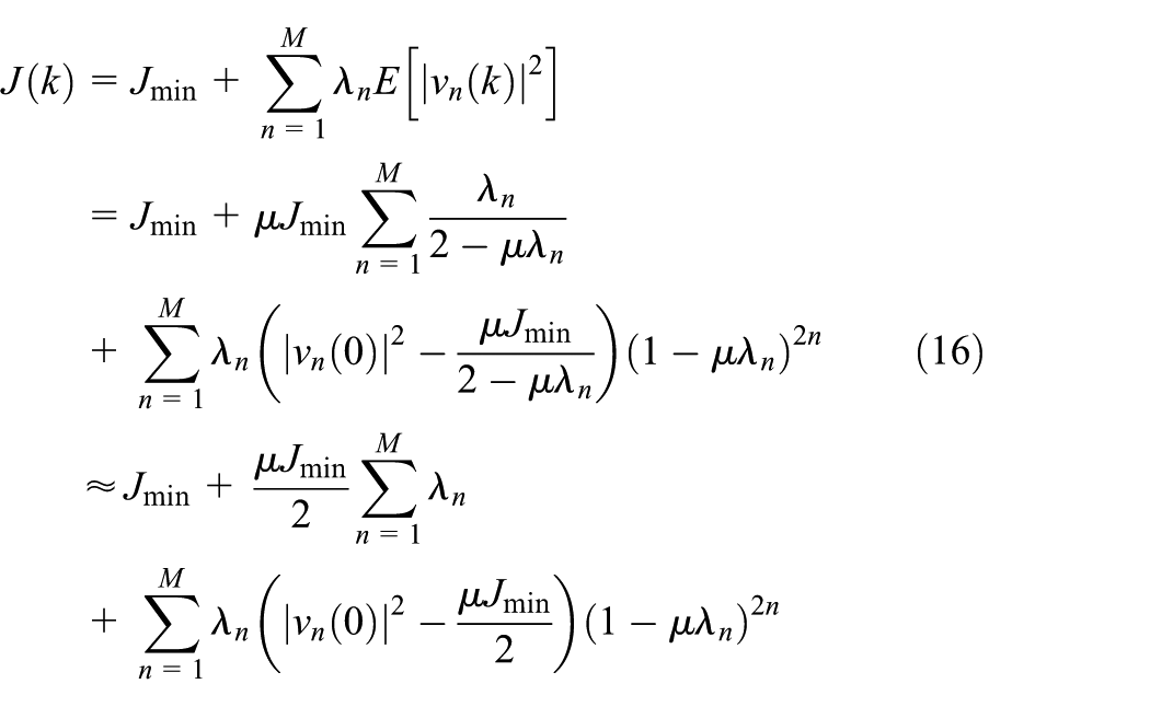
Based on the small-step theory, the exponent term
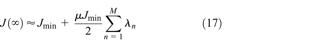
In order to ensure the cost function convergence,
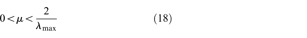
where
Amplitude phase controller
The system reference signal is a sine wave with angular frequency ω, which can be expressed by

The acceleration response signal can be expressed by

where Am is the amplitude of the measured acceleration response signal, and φ is the phase delay of the acceleration response signal. The error of the electro-hydraulic system is

Therefore, it is possible to eliminate the phase delay as long as the acceleration response signal obtain a corresponding phase advance φ, and the reference signal will be converted as follows (Yao et al., 2013)

where w1 and w2 are two weights of the APC,

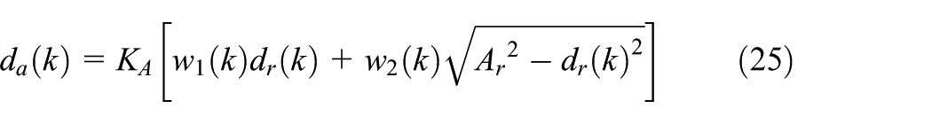
The APC controller is employed to reduce the amplitude attenuation and phase delay of the acceleration response signal by converting the reference signal to the advanced signal. Its block diagram is demonstrated in Figure 3, where KA is the amplitude gain to adjust the acceleration signal.
Block diagram of the amplitude phase controller.
According to Figure 3, the converted signal
And the block diagram of the APC is simplified as shown in Figure 4, where

Simplified block diagram of the amplitude phase controller.
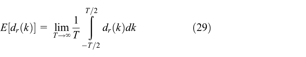
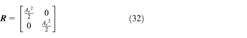
The stability of the APC is dependent on the adjustment of the weight vector, which is iterative adjusted until the control system is stable. The input vector can be expressed by

where
According to (18), stability of the LMS is associated with the eigenvalues of the correlation matrix
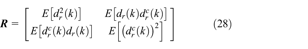
Because
Thus

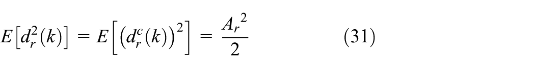
Substituting (30) and (31) into (28),
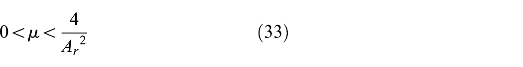
Then, according to (18), the necessary stability condition of the APC is
ZPTEC
The ZPETC here is applied to improve the convergence speed, which can also achieve the offline phase compensation. In addition, the ZPETC can compensate the phase error caused by the unstable zeros, and the discrete transfer function of the controlled object is (Shen et al., 2013)
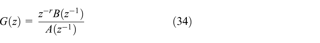
where z−r is the lag caused by the model delay, r is the delay step,

where

And the ZPETC can be modeled by
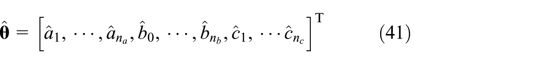
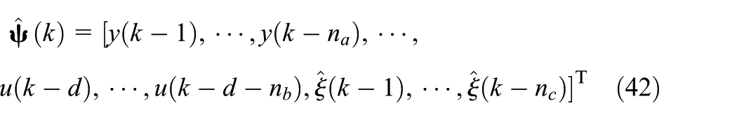
Before going through the controller design, the system parameters will be identified. There are some common methods used to identify the nonlinear system parameters currently. The recursive least square algorithm and its improved form have been applied to the online model identification of the vibration system, which presented good performance in the vibration testing (Rigney et al., 2010; Sum and Ho, 2006). As a basic method of model identification, the recursive extended least square(RELS)method possess the advantages of simple calculation and good astringency. The estimate equation of the RELS can be expressed by (Shen et al., 2013)
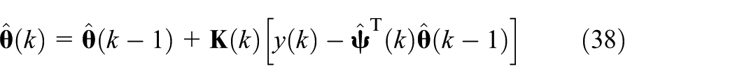
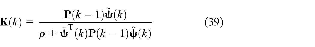
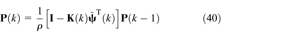
where
Discrete feed-forward compensator
In order to compensate the actuator delay, a DFC has been introduced into the feed-forward scheme presented previously (Jung and Shing, 2006). And the DFC is simple to implement and easy to apply with good performance. Firstly, it can be assumed that the displacement errors within a time step are similar to those in the previous step. Then, the corrected displacement can be expressed by
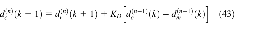
where n is the total number of iterations,
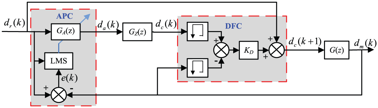
Block diagram of the proposed controller.
According to Figure 5, the measured signal can be expressed by

Substituting (44) into (21), the tracking error can be expressed by
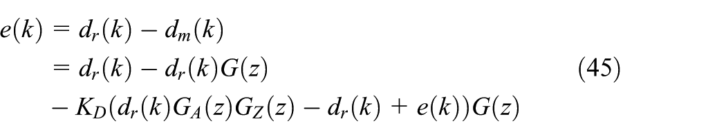
which can be further simplified as follows
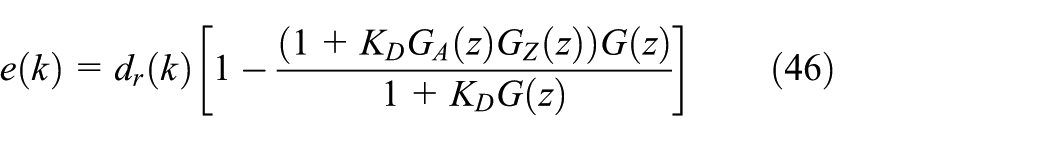
In order to improve the tracking performance, the error

Combining (46) with (47) results in the following equation
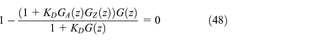
where

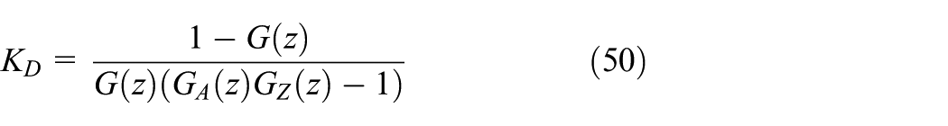
To obtain good convergence, the value of the DFC gain
TVC
The TVC is a basic control strategy of the shaking table testing, and there are three variables corresponding to the displacement, velocity and acceleration, respectively. As shown in Figure 6, The TVC consists of three variable feed-forward and feedback controllers. The former is aiming at extending the frequency bandwidth of the closed-loop by tuning three feed-forward parameters,
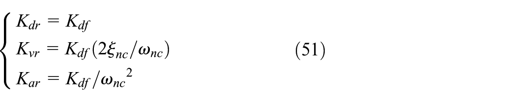
where
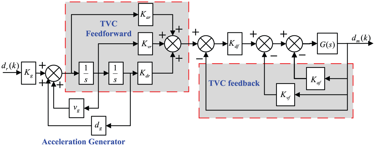
Block diagram of the TVC.
The transfer function of the TVC can be expressed by (Shen et al., 2013)
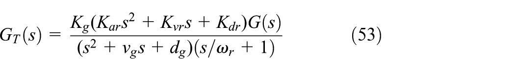
where
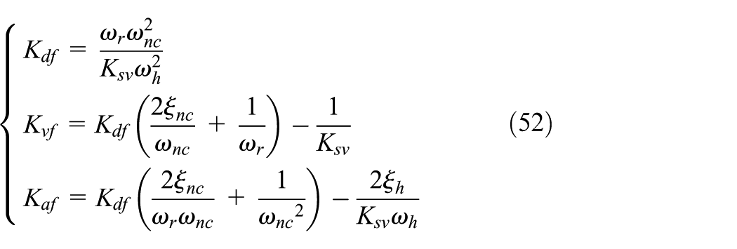
The feedback and feed-forward parameters of the TVC controller are initially calculated according to (51) and (52). But in the actual test process, the parameters should be further adjusted. Firstly, it adjusts the acceleration feedback parameter until the system is divergent. Secondly, it adjusts the values of
Simulation results and analysis
Modeling of the zero phase error tracking controller
The identified transfer function of the experimental system with RELS can be expressed by

The precision of the ZPETC depends on the accuracy of the identification model. In order to evaluate the model precision identified by the RELS algorithm, the frequency response of the identified model and the experimental system are presented in Figure 7. It can be seen that the identified model using the RELS algorithm conforms to the experimental results, and the identification accuracy is degraded with the increase of the frequency.
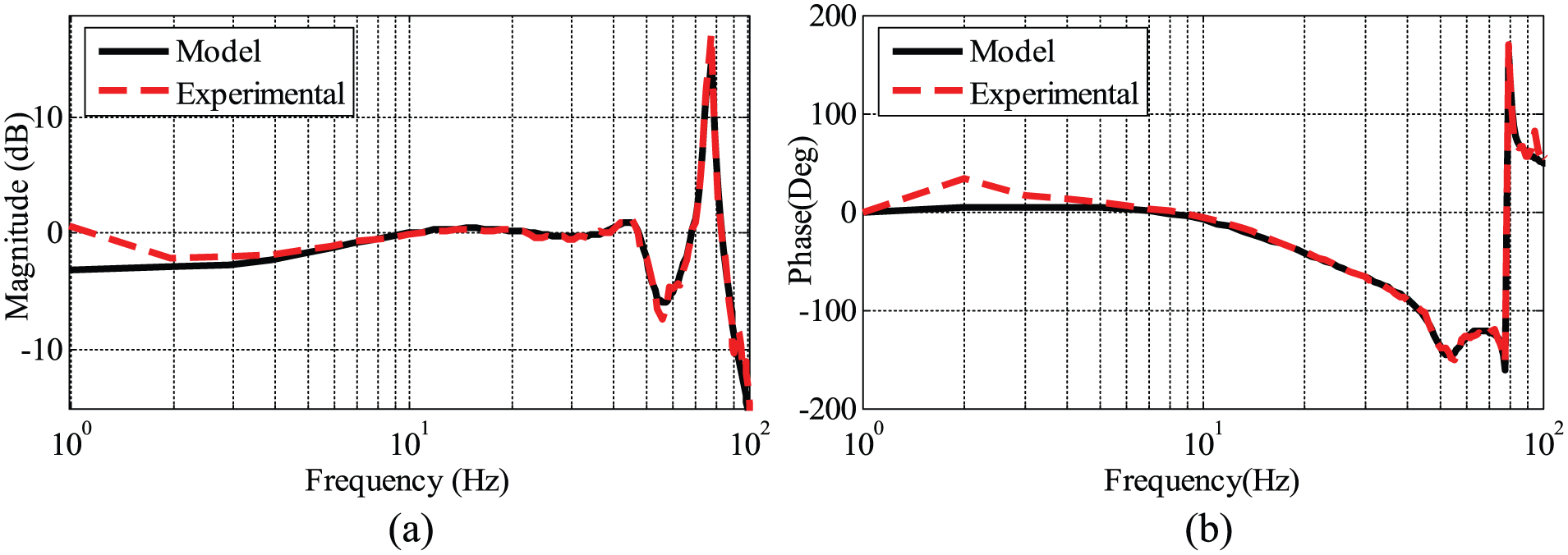
Frequency characteristics with experimental and identified model: (a) magnitude frequency characteristics; (b) phase frequency characteristics.
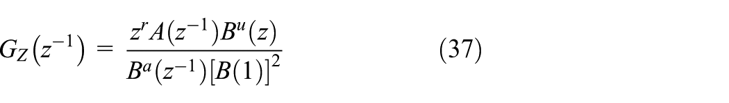
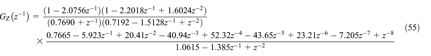
According to the identified transfer function, the zeros and poles can be expressed as follows
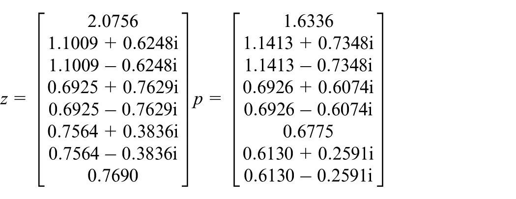
Apparently, there are three unstable zeros outside the unit circle, so the electro-hydraulic system is a non-minimum-phase system. And computed with (34)–(37), the transfer function of the ZPETC can be described by
Simulation results
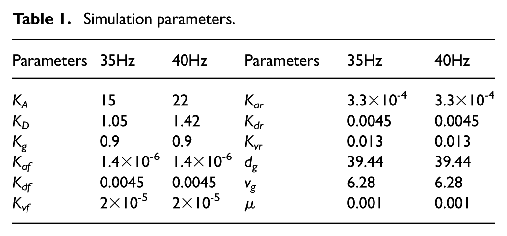
In order to verify the performance of the proposed controller, simulations are performed on the simulation model. Mean square errors of the acceleration tracking accuracy excited by a sine signal of 35Hz and 40Hz are shown in Figure 8 with different controllers, and the simulation parameters are listed in Table 1. It can be clearly observed that the parameters of the TVC controllers will not be changed as long as these parameters are adjusted according to the third section. Besides, the values of the parameters
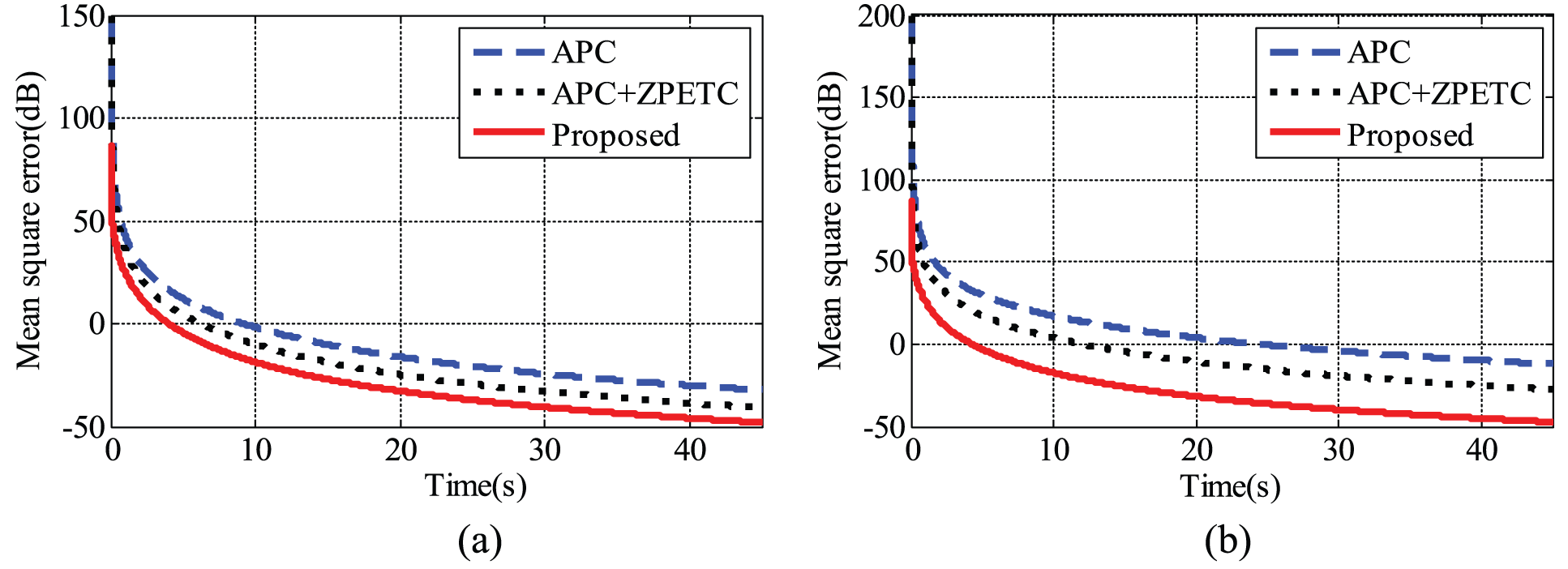
Simulation results of mean square errors at 35Hz and 40Hz with different controllers: (a) 35 Hz; (b) 40 Hz.
Simulation parameters.
Experimental setup and results
Experimental setup
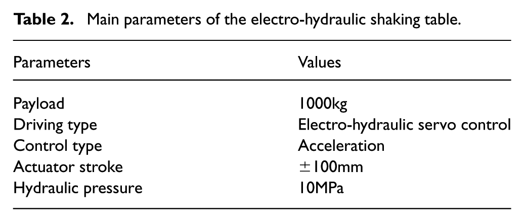
An experimental system of the EHST is presented in Figure 9, mainly composed of two servo valves, two hydraulic actuators, two filters and a payload. There are two double ended hydraulic actuators on the opposite sides of the payload symmetrically, which is controlled by servo valves with the same operating principle. As shown in Figure 9, two hydraulic actuators are connected with the payload by two spherical joints, which have 70 mm bore and 50 mm rod controlled by the Moog two stage servo-valves with a 38 L/min flow capacity at 7 MPa supply pressure. The hydraulic actuators provide the driving force with the accelerometer installed on the drive rod. And the main system parameters of EHST system are listed in Table 2.
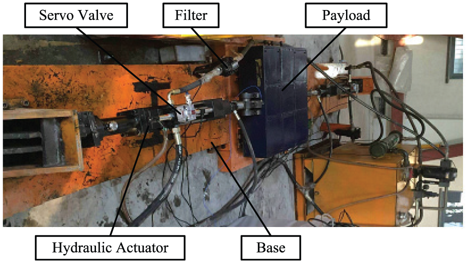
Experimental system of the electro-hydraulic shaking table.
Main parameters of the electro-hydraulic shaking table.
As the basis of the EHST, the hardware consists of a hydraulic power unit, two signal conditioners, two data acquisition cards, two accelerometers, and so on. All the sensor signals, test signals and digital I/O signals related to the EHST system are adjusted by the signal conditioners. An A/D card PCI-1716 and a D/A card ACL-6126 are utilized to convert signals with sample frequency 100 kHz. Besides, the accelerometer G3711 sensor is made by PCB corporation with the measuring range of ±2g and the measuring accuracy of ±0.1%.
Experimental results
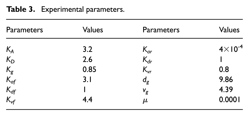
As shown in Figure 10, the frequency characteristics are compared with the proposed phase compensator and TVC. Moreover, the proposed phase compensator performs better tracking accuracy with lower amplitude attenuation and phase delay. The experimental parameters are listed in Table 3.
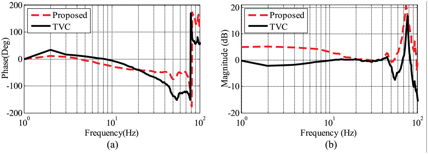
Frequency characteristics comparison with the proposed controller and the TVC: (a) magnitude frequency characteristics; (b) phase frequency characteristics.
Experimental parameters.
The reference signal 0.2sin50πt is applied as the shaking table excitation, and the following Figure 11 and Figure 12 present the adaptive tuning process of the acceleration response and its detailed measured signal with different controllers. Comparing Figure 11(a) with (b) and Figure 12(a) with (b), the ZPETC can not only improve the convergence speed but also compensate the phase delay of the APC significantly. Additionally, the DFC can further improve the convergence speed and compensate the phase delay according to the Figure 11(c) and Figure 12(c). As shown in Figure 13, the proposed controller has the fastest convergence speed as well as the highest tracking accuracy compared with the other two controllers, and the mean square errors are -21 dB, 10 dB and -2.5 dB, respectively. It can be obviously seen from Figure 11, Figure 12 and Figure 13 that the proposed controller performs the best tracking performance.
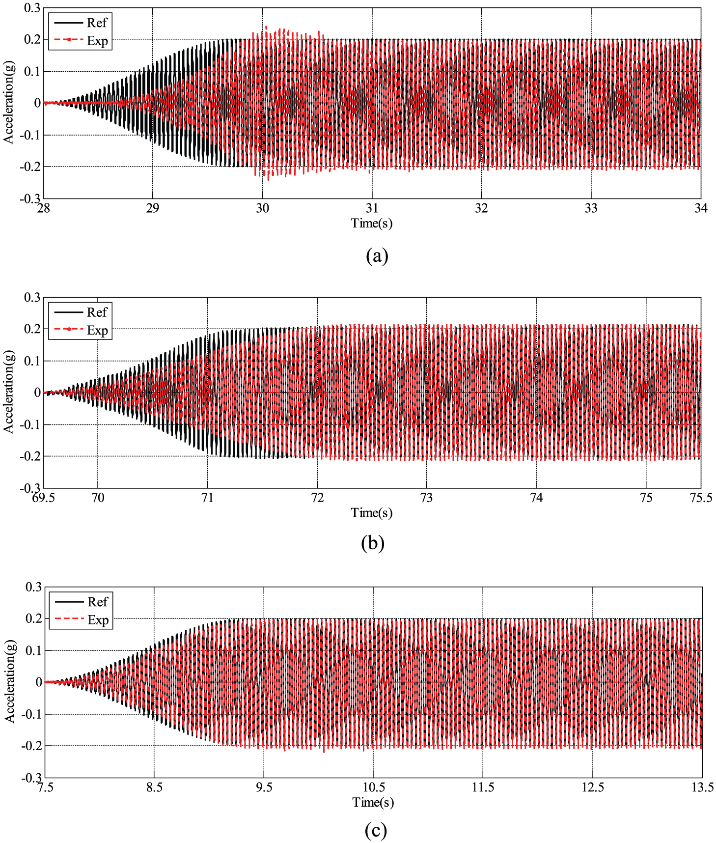
Experimental results using a 25Hz sine signal with different controllers: (a) amplitude phase controller; (b) amplitude phase controller + zero phase error tracking controller; (c) proposed controller.
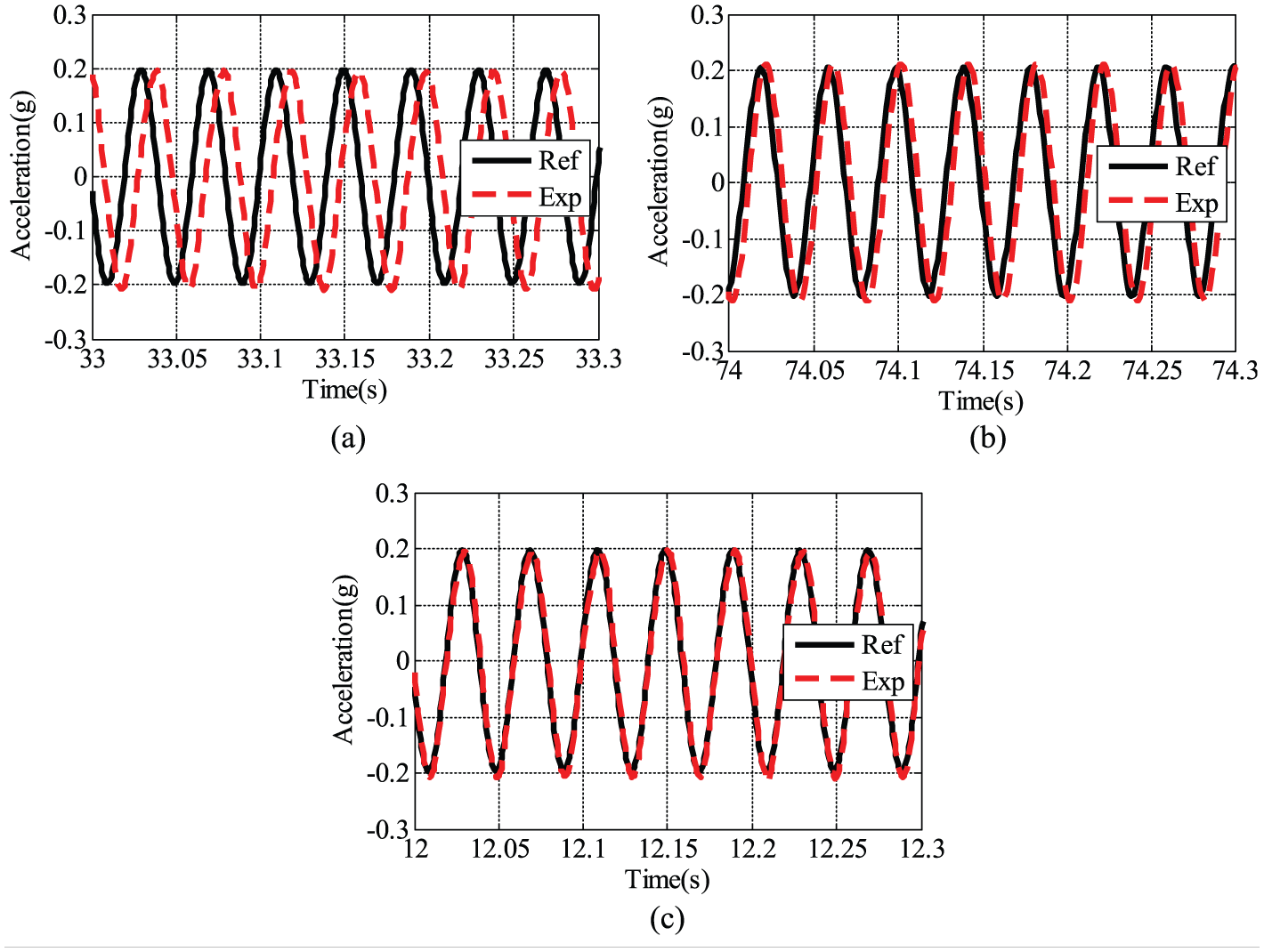
Detailed experimental results using a 25Hz sine signal with different controllers: (a) amplitude phase controller; (b) amplitude phase controller + zero phase error tracking controller; (c) proposed controller.
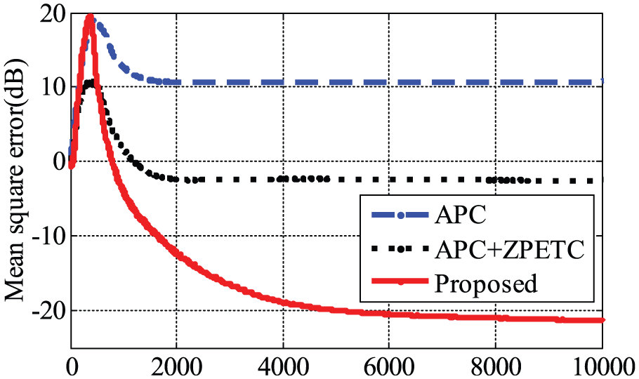
Mean square errors of the acceleration response with different controllers.
Conclusion
A novel controller for acceleration response control is proposed to improve the acceleration replication accuracy of the EHST, and a parameter transfer function of the acceleration closed-loop system can be identified by the RELS algorithm for offline compensating phase delay achieved by the ZPETC. What is more, the effectiveness of the proposed control strategy is verified via simulated and experimental results on the EHST, and it shows a significant enhancement in the acceleration tracking accuracy when the proposed combined controller is applied. The phase compensation method could effectively reduce the phase delay errors.
Footnotes
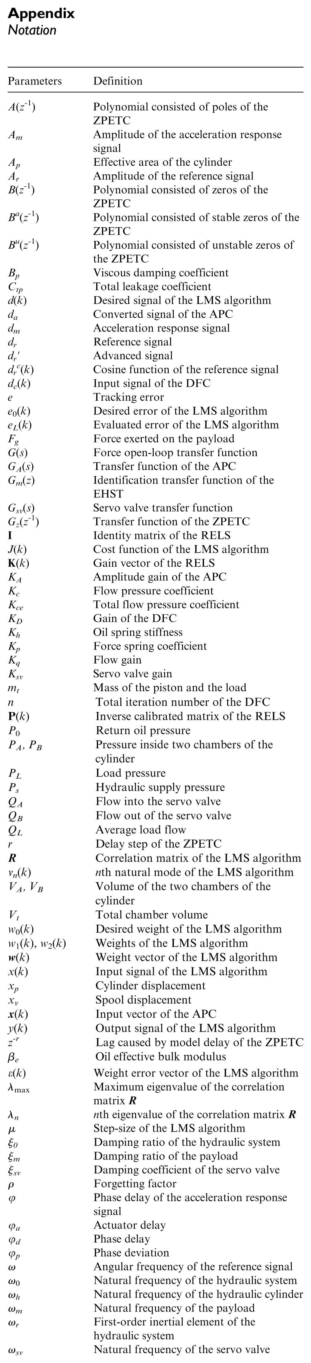
Appendix
Notation
| Parameters | Definition |
|---|---|
| A(z−1) | Polynomial consisted of poles of the ZPETC |
| Am | Amplitude of the acceleration response signal |
| Ap | Effective area of the cylinder |
| Ar | Amplitude of the reference signal |
| B(z−1) | Polynomial consisted of zeros of the ZPETC |
| Ba(z−1) | Polynomial consisted of stable zeros of the ZPETC |
| Bu(z−1) | Polynomial consisted of unstable zeros of the ZPETC |
| Bp | Viscous damping coefficient |
| Ctp | Total leakage coefficient |
| d(k) | Desired signal of the LMS algorithm |
| da | Converted signal of the APC |
| dm | Acceleration response signal |
| dr | Reference signal |
| dr′ | Advanced signal |
| drc(k) | Cosine function of the reference signal |
| dc(k) | Input signal of the DFC |
| e | Tracking error |
| e 0(k) | Desired error of the LMS algorithm |
| eL(k) | Evaluated error of the LMS algorithm |
| Fg | Force exerted on the payload |
| G(s) | Force open-loop transfer function |
| GA(s) | Transfer function of the APC |
| Gm(z) | Identification transfer function of the EHST |
| Gsv(s) | Servo valve transfer function |
| Gz(z−1) | Transfer function of the ZPETC |
|
|
Identity matrix of the RELS |
| J(k) | Cost function of the LMS algorithm |
|
|
Gain vector of the RELS |
| KA | Amplitude gain of the APC |
| Kc | Flow pressure coefficient |
| Kce | Total flow pressure coefficient |
| KD | Gain of the DFC |
| Kh | Oil spring stiffness |
| Kp | Force spring coefficient |
| Kq | Flow gain |
| Ksv | Servo valve gain |
| mt | Mass of the piston and the load |
| n | Total iteration number of the DFC |
|
|
Inverse calibrated matrix of the RELS |
| P 0 | Return oil pressure |
| PA, PB | Pressure inside two chambers of the cylinder |
| PL | Load pressure |
| Ps | Hydraulic supply pressure |
| QA | Flow into the servo valve |
| QB | Flow out of the servo valve |
| QL | Average load flow |
| r | Delay step of the ZPETC |
|
|
Correlation matrix of the LMS algorithm |
| vn(k) | nth natural mode of the LMS algorithm |
| VA, VB | Volume of the two chambers of the cylinder |
| Vt | Total chamber volume |
| w 0(k) | Desired weight of the LMS algorithm |
| w 1(k), w2(k) | Weights of the LMS algorithm |
|
|
Weight vector of the LMS algorithm |
| x(k) | Input signal of the LMS algorithm |
| xp | Cylinder displacement |
| xv | Spool displacement |
|
|
Input vector of the APC |
| y(k) | Output signal of the LMS algorithm |
| z−r | Lag caused by model delay of the ZPETC |
| βe | Oil effective bulk modulus |
| ε(k) | Weight error vector of the LMS algorithm |
| λ max | Maximum eigenvalue of the correlation matrix |
| λn |
nth eigenvalue of the correlation matrix |
| μ | Step-size of the LMS algorithm |
| ξ0 | Damping ratio of the hydraulic system |
| ξm | Damping ratio of the payload |
| ξsv | Damping coefficient of the servo valve |
| ρ | Forgetting factor |
| φ | Phase delay of the acceleration response signal |
| φa | Actuator delay |
| φd | Phase delay |
| φp | Phase deviation |
| ω | Angular frequency of the reference signal |
| ω 0 | Natural frequency of the hydraulic system |
| ωh | Natural frequency of the hydraulic cylinder |
| ωm | Natural frequency of the payload |
| ωr | First-order inertial element of the hydraulic system |
| ωsv | Natural frequency of the servo valve |
Declaration of conflicting interest
The authors declare that there is no conflict of interest.
Funding
This research was supported by the National Natural Science Foundation of China (No. 51575511), Program for Changjiang Scholars and Innovative Research Team in University (No. IRT_16R68), the Fundamental Research Funds for the Central Universities in China (No. 2015XKMS025), and the Research Innovation Program for College Graduates of Jiangsu Province (No. KYLX16_0524), the Project Funded by the Priority Academic Program Development of Jiangsu Higher Education Institutions (PAPD) and the Qing Lan Project in Jiangsu province.