
Abstract
In the magnetic fields built by neodymium–iron–boron (NdFeB) permanent magnets, the corresponding relationship among the concentration of sodium chloride solution, glucose solution and their magnetic rotation angles was researched in the temperature range 20–24°C. A helium–neon (He–Ne) laser with a wavelength of 632.8 nm was used in the experiment as light source. A new device is designed for assembling and adjusting the NdFeB permanent magnets. The permanent magnets have no thermal effect compared to an energized solenoid. The corresponding relationship between the concentration and rotation angle is calibrated by standard concentration gradient solutions. Then the concentration can be detected by using this relationship. The rotation angle of the solution is proportional to the concentration and increased with an increase of the magnetic induction intensity. In the magnetic cavity with Φ12 mm dimension, the rotation angles of sodium chloride solutions in the range 0–30 g/100 ml vary from 2.66° to 3.73° and their relative errors range from −1.39% to 1.34%. The rotation angles of glucose solutions in the range 0–50 g/100 ml vary from 2.66° to 26. 44° and their relative errors range from −0.55% to 1.00%. The uncertainty of this system is 0. 05°.
Keywords
Introduction
Concentration is one of the key physical and chemical parameter to describe the characteristics of solutions. A fast and accurate method of solution concentration measurement, which has actual benefits for industrial production, can improve production efficiency and ensure product quality. Optical methods such as polarimetry and interferometry are often used in solution concentration measurement. Twu et al. (2017) proposed a single-channel common-path interferometer for measuring the optical activity of chiral solutions based on homodyne technology. Guerreroméndez et al. (2017) used digital holographic interferometry (DHI) to measure the concentration differences between liquid mixtures. The typical application of polarimetry is the polarimetric saccharimeter, which has been widely used in the sugar industry. One of the major drawbacks of polarimetric saccharimeter is that it can only detect the chiral materials and can do nothing for the general solutions. However, achiral materials will have optical activity in a magnetic field. This phenomenon is known as the magneto-optical effect. We can take advantage of this effect to avoid the shortcoming of the saccharimeter.
The magneto-optical effect was first discovered by Faraday in the nineteenth century but it did not have practical applications until the laser was invented. Measurements based on the magneto-optical effect have now been extensively researched. Novotný et al. (2002) detected the existence of the leakage field around a fatigue crack in nonmagnetic austenitic material using a highly sensitive magneto-optic film through the method for imaging and measuring of magnetic fields on micrometre scale. Then they reviewed the application of magneto-optic films in non-destructive evaluation (NDE). Clark et al. (2012) measured the magnetic field in low density plasmas using a paramagnetic Faraday rotator glass with a high Verdet constant. A Faraday rotator glass is a modulation device based on the magneto-optical effect. Liu et al. (2014) measured the anisotropic thermal conductivity of molybdenum disulfide by the time-resolved magneto-optical Kerr effect. Li (2015) investigated the mutual compensation property between electro-optical and magneto-optical modulations in a crystal with electro-optical and magneto-optical effects. He also researched its application to magneto-optical sensor theoretically and experimentally. Kalish and Belotelov (2016) proposed methods for magneto-optical detection of the in-plane magnetization in a magnetic film due to the deposition of a one-dimensional metallic diffraction grating on the film. Some scholars have also applied the magneto-optical effect to the field of solution concentration detection. Anand et al. (2016) designed a single wristwatch-style device for non-contact measurement of glucose concentration in the blood stream using the magneto-optic effect. This device contains an AC (alternating) electro-magnet generated by a solenoid, a laser and a camera. Xiao et al. (2010) reported research on technology for measuring the concentration of a two-component solution by using quadrature AC magneto-optical modulation. This approach requires that the solution has one and only one component with optical activity. A double optical path method is used to improve the detection sensitivity.
The traditional magneto-optical effect experiment generally uses a solenoid to establish the magnetic field. But the solenoid coil has obvious thermal effects. In this paper, we present a new method for measuring the solution concentration based on the magneto-optical effect in a permanent magnetic field. We build the permanent magnetic field through some neodymium–iron–boron (NdFeB) permanent magnets. The permanent magnets do not exhibit the thermal effect. The achiral solutions have optical activity in the magnetic field so the concentration can be detected. This method expands the range of material which can be used in polarimetry and it is a non-destructive measurement.
Measurement principle
The phenomenon observed if linearly polarized light passes through a material placed in magnetic field then the plane of polarization is rotated is called the magneto-optical effect. The angle through which the polarization is rotated depends on the strength of the magnetic field in the direction of propagation and the length of the material. Its empirical formula is
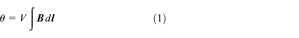
where V is the Verdet constant and the integral expression represents the magnetic field
Dielectric constant tensors and Maxwell equations are used to describe the magneto-optical effect in its classical theory. The magneto-optical effect is the result of the interaction between the magnetic moment of a material and the magnetic field. Linear and nonlinear magneto-optical absorption via one- and two-photon processes in a quantum well modulated by an intense laser field have been studied numerically (Phuc et al., 2016). The Verdet constant V is related to the laser wavelength. In addition, different types and concentrations of material also change the Verdet constant. Some researchers have focused on investigation of improving characteristics of the magneto-optical effect by changing material constituents (Chen et al., 2016; Lei et al., 2016; Zhang et al., 2017). For the determined magnetic field intensity, laser wavelength, length of the material and the same environmental conditions, the rotation angle of the solution is in one-to-one correspondence with its concentration. Based on this, the solution concentration can be deduced by measuring its rotation angle.
There is no direct sensor to measure the polarization angle of a laser at present. Ozana et al. (2016) designed a noncontact speckle-based optical sensor for the detection of the rotation angle of glucose. Wang et al. (2016) proposed fibre link equipment for optical rotation measurement based on the AC-DC modulation magneto-optical effect. Niu (2016) used a polarizing beam splitter-based sensor to measure the polarization angle. The polarized light extinction method was used in the experiment. Compared to the traditional light extinction method, an absolute encoder and a high-precision laser power meter are added in order to improve the precision. The improved polarization extinction system is shown in Figure 1. The polarizer is placed orthogonal to the analyser and their extinction ratios are both 1:500. The laser beam emitted by the helium–neon (He–Ne) laser passes through the polarizer and becomes linearly polarized light. The polarized light is then sent through the solution in the magnetic field so that the plane of polarization is rotated by an angle. Then the polarized light is no longer orthogonal to the analyser so it can pass through the analyser and into the laser power meter based on the Malus law. An LP1 laser power meter produced by Sanwa Electric Instrument Co. is used and its measuring range is 0.01 μW–40 mW. Rotating the analyser to make the value of the laser power meter a minimum again, then the angle through which the analyser is rotated is just the same as the angle of the magneto-optical rotation of the solution. The direction of the magneto-optic rotation is the same as the direction through which the analyser is rotated and the angle is output by the absolute rotary encoder that is fixed with the analyser. The encoder used is produced by Denmark Scancon Encoders A/S and its revolution is 13 bit.
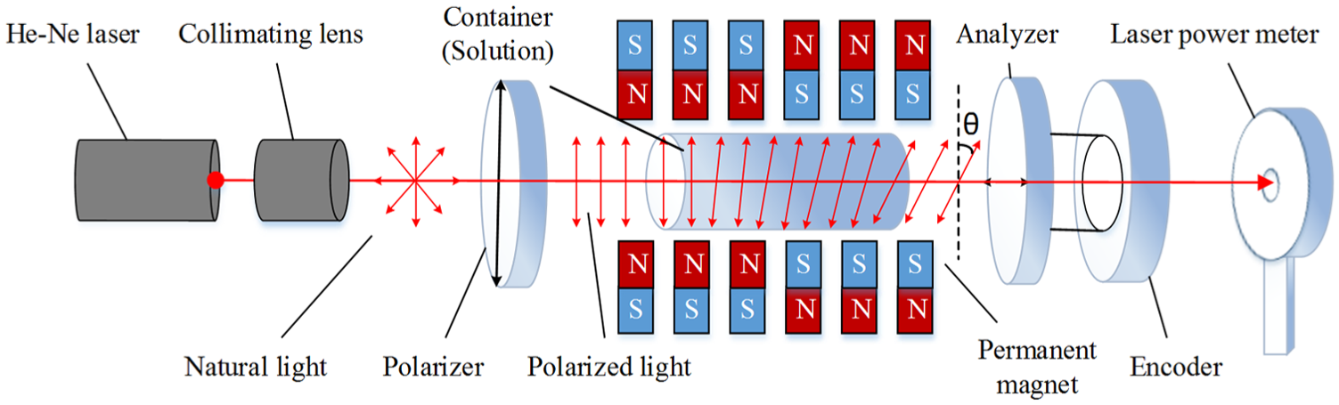
Improved polarization extinction test system.
Establishment and simulation of magnetic field
The magnetic field is one of the most important factors in the experiment. Research on the value and distribution of the magnetic field is necessary. The traditional magneto-optical effect experiment generally uses a solenoid to establish the magnetic field. But a solenoid coil has an obvious thermal effect. The time of experiment needs to be controlled in order to confine rise of temperature, otherwise the measurement accuracy will be affected. Thus, NdFeB permanent magnets are used in place of a solenoid in order to have better measurement stability. Bloch et al. (1998) reported innovative approaches to the generation of intense magnetic fields by a 4 T permanent magnet. Pradeep et al. (2017) used permanent magnets in a simple quadratic magneto-optical Kerr effect measurement system. The type of the NdFeB permanent magnets used in the experiment is N35. The coercivity
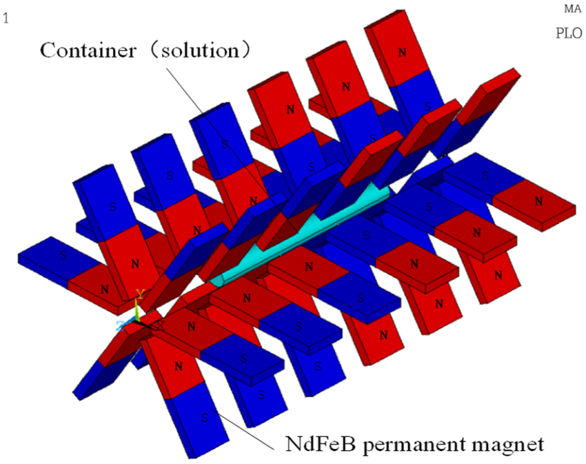
Space structure of the NdFeB permanent magnets.
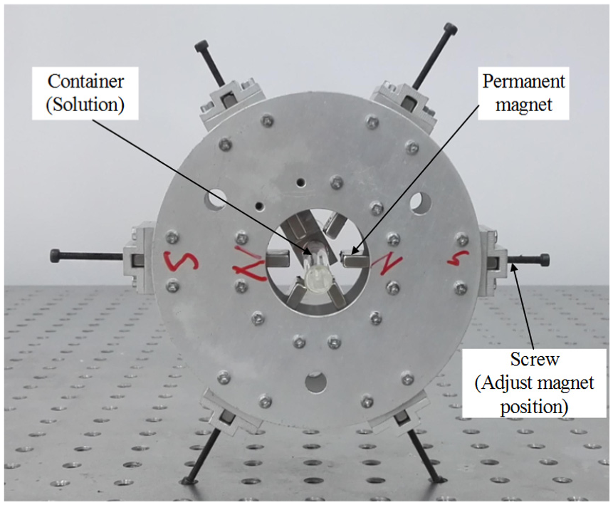
Based on the model shown in Figure 2, a new device is designed for assembling and adjusting the permanent magnets. The device is made of aluminium alloy, whose permeability is approximately 1, just the same as the atmosphere. The device, which consists of six parts, is shown in Figure 3. Figure 4 shows one part of the device separately. Screws that bear on each permanent magnet are placed in the peripheral part of device. Therefore, the space position of the permanent magnets can be controlled by screwing in and out of the screws so as to change the size of the magnetic cavity that is defined as the region enclosed by the permanent magnets. The diameter of the container containing a solution is Φ10 mm and its length is 10 cm. The container is placed in the centre of the permanent magnetic field.
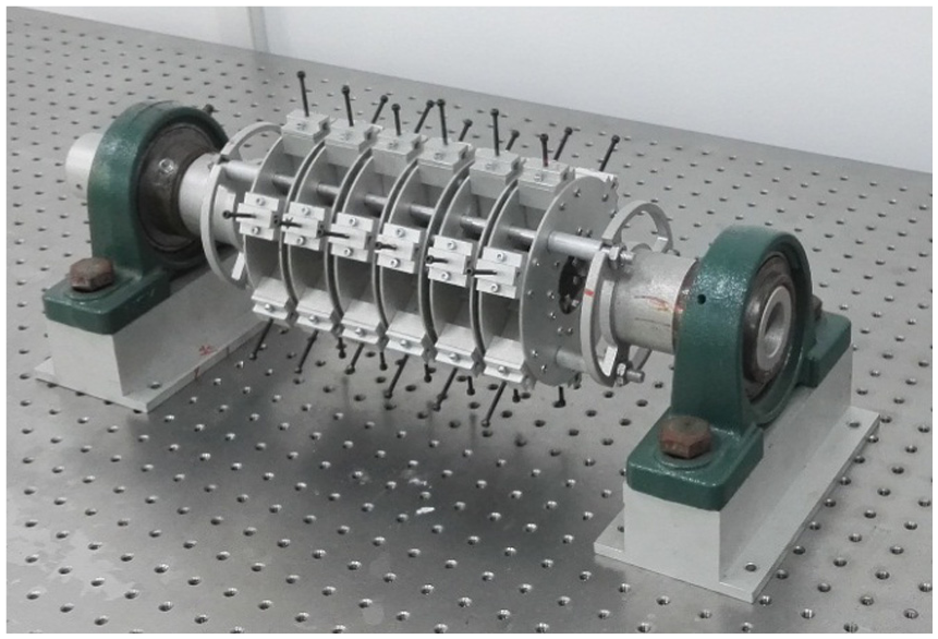
Permanent magnets assembling device
One part of the device.
The experiments are carried out under three magnetic field conditions, namely, Φ12 mm, Φ16 mm and Φ20 mm diameters of magnetic cavity. The ANSYS finite element simulation of those conditions is finished and the pictures of magnetic induction vector are obtained. The magnetic field where the solution is located is displayed because we are more concerned with this magnetic field rather than the overall magnetic field. Taking the Φ12 mm magnetic cavity as an example, the simulation result of magnetic field is shown in Figure 5. The simulation result shows that the magnetic field at the centre position is the strongest and decreases gradually to both sides. In addition, with the decrease of the diameter of the magnetic cavity, the magnetic induction intensity increases.
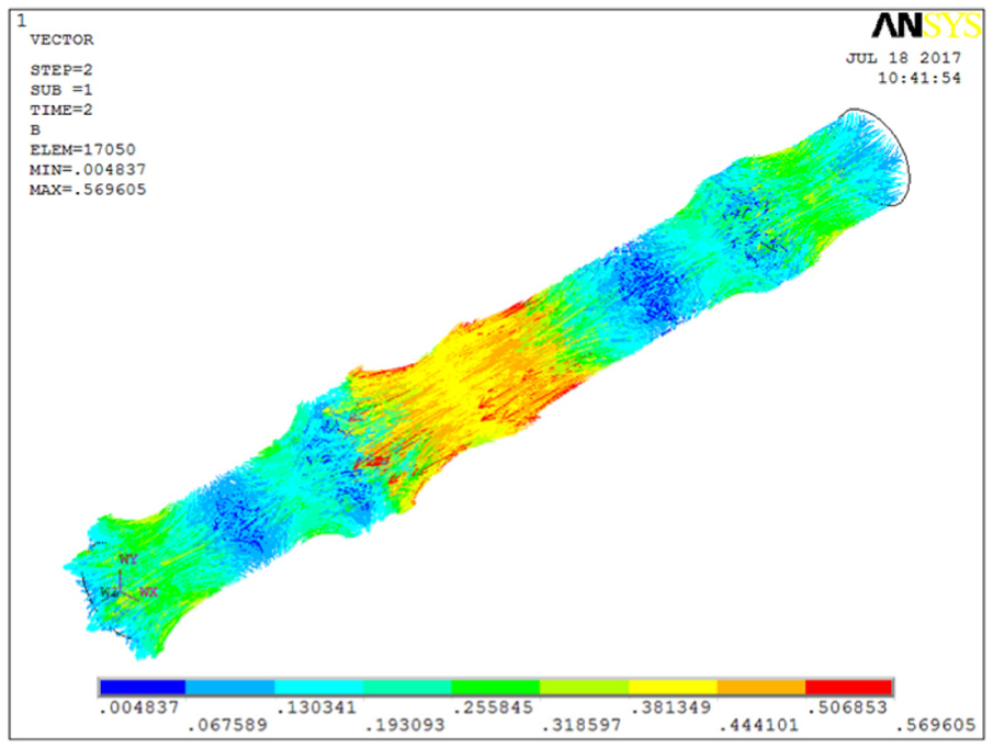
ANSYS simulation of the Φ12 mm magnetic cavity.
Experiment analysis
Sodium chloride solution and glucose solution were used as the test objects. A series of gradient concentration solutions were prepared first using an electronic balance of 0.01 g resolution, volumetric flasks, beakers, glass rods and droppers, etc. Sodium chloride concentration gradient solutions ranged from 3 g/100 ml to 30 g/100 ml with an interval of 3 g/100 ml. The glucose concentration gradient solutions ranged from 5 g/100 ml to 50 g/100 ml with an interval of 5 g/100 ml. The corresponding relationship between the concentration and the rotation angle can be calibrated by these standard concentration gradient solutions. Under three magnetic conditions, the magnetic induction intensity at which the solution is located is measured at 0.5 cm interval through the Tesla meter of 0.1 mT resolution. The data is basically consistent with the simulation. Fitting curves are obtained with these data through a least squares method. The average intensity of magnetic induction is calculated by integrating the curve and divided by the length. The average intensity of magnetic induction of three magnetic conditions is shown in Figure 6.
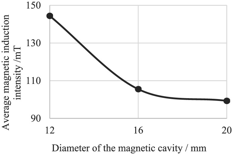
Average magnetic induction in different diameters of magnetic cavity.
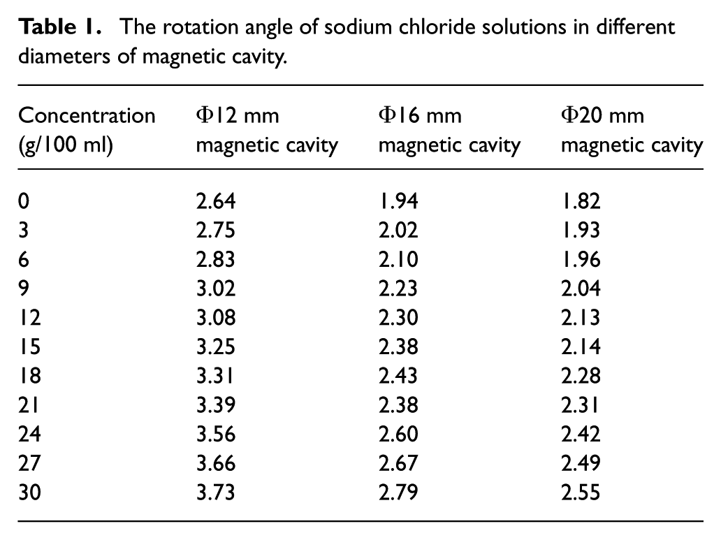
The test platform is shown in Figure 7. It is found that the magneto-optical effect of sodium chloride solution is left-handed, and the result is shown in Figure 8. The specific data are shown in Table 1. The data in Table 1 are the average of five measurements. As can be seen from Figure 8, the rotation angle is basically proportional to its concentration under all three magnetic conditions. With the decrease of the diameter of the magnetic cavity, the rotation angles increase. In the magnetic cavity with Φ12 mm dimensions, the rotation angles are maximum; the angles of 0–30 g/100 ml sodium chloride solutions vary from 2.66° to 3.73°. Based on the empirical formula for the magneto-optic effect and measured data of sodium chloride, the mean magnetic induction intensity B and concentration c multiplied by magnetic induction B are taken as independent variables and the rotation angle

where the unit of
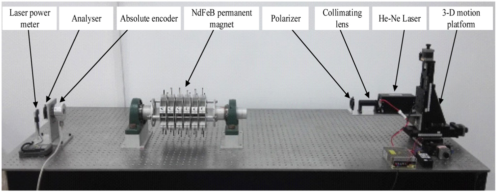
Experimental platform.
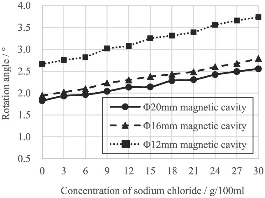
Rotation angles of gradient sodium chloride solutions in different diameters of magnetic cavity.
The rotation angle of sodium chloride solutions in different diameters of magnetic cavity.
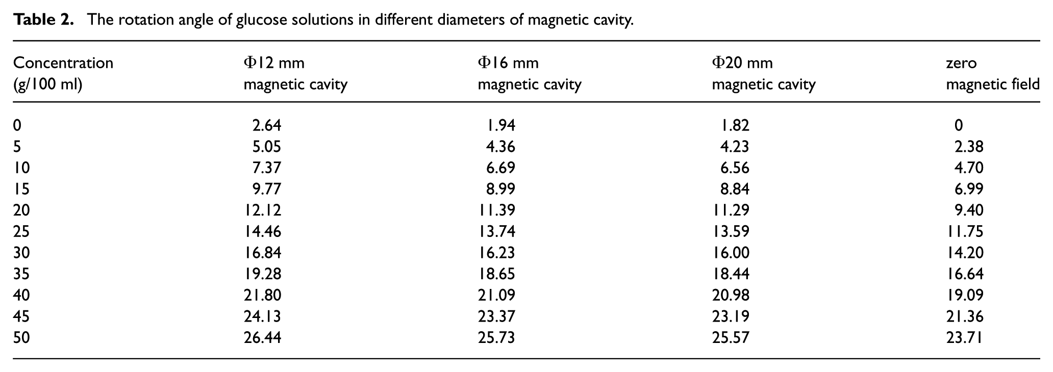
Since a glucose solution has optical activity itself, the research in zero magnetic field was added. Glucose solution was taken as an example to research whether the optical activity of chiral materials changes in a magnetic field. It is found that the optical activity of glucose solution itself is right-handed, and the rotation angles become smaller when they are in the magnetic field, indicating that the rotation of the magneto-optical effect is left-handed. The magnetic field is reversed in order to make the direction of rotation the same. Figure 9 shows the results for glucose. The specific data is shown in Table 2. As above, the data in Table 2 represent the average of five measurements. Glucose without magnetic field already has an obvious optical activity. In the other three kinds of magnetic field conditions, the slope of the fitting curves of the rotation angle and their concentration is basically the same. It can be inferred that the optical activity of glucose does not change in the magnetic field. Put another way, glucose exhibits no magneto-optical effect, or its magneto-optical effect is very weak. The method of measuring the solution concentration based on magneto-optical effect is also applicable for chiral materials. In the magnetic cavity with Φ12 mm dimensions, the rotation angles are maximum; the angles of 0–50 g/100 ml glucose solutions vary from 2.66° to 26.44°. Based on the empirical formula of magneto-optical effect and measured data of glucose, the mean magnetic induction intensity B and concentration c are taken as independent variables, the rotation angle

where the unit of
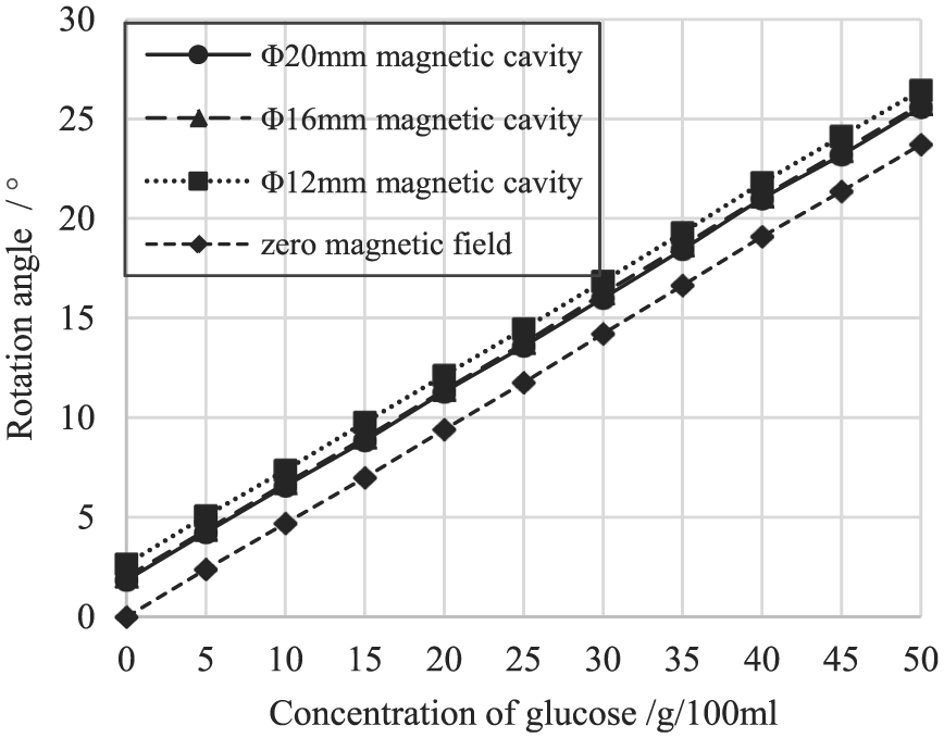
Rotation angles of gradient glucose solutions in different diameters of magnetic cavity.
The rotation angle of glucose solutions in different diameters of magnetic cavity.
Error analysis
The sensitivity of this system is the ratio of the increment of the rotation angle to the increment of the concentration. The sensitivity of sodium chloride solution increases with the increase of magnetic field and it is 3.65° ml/g in the magnetic cavity with Φ12 mm dimensions. That means, when the concentration of sodium chloride is increased by 1 g/100 ml, the rotation angle increases by 0.0365°. The sensitivity of glucose solution is 47.7° ml/g and does not change with the change of the magnetic field. That means, when the concentration increases by 1 g/100 ml, the rotation angle increases by 0.477°. The fitting error
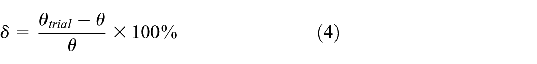
where
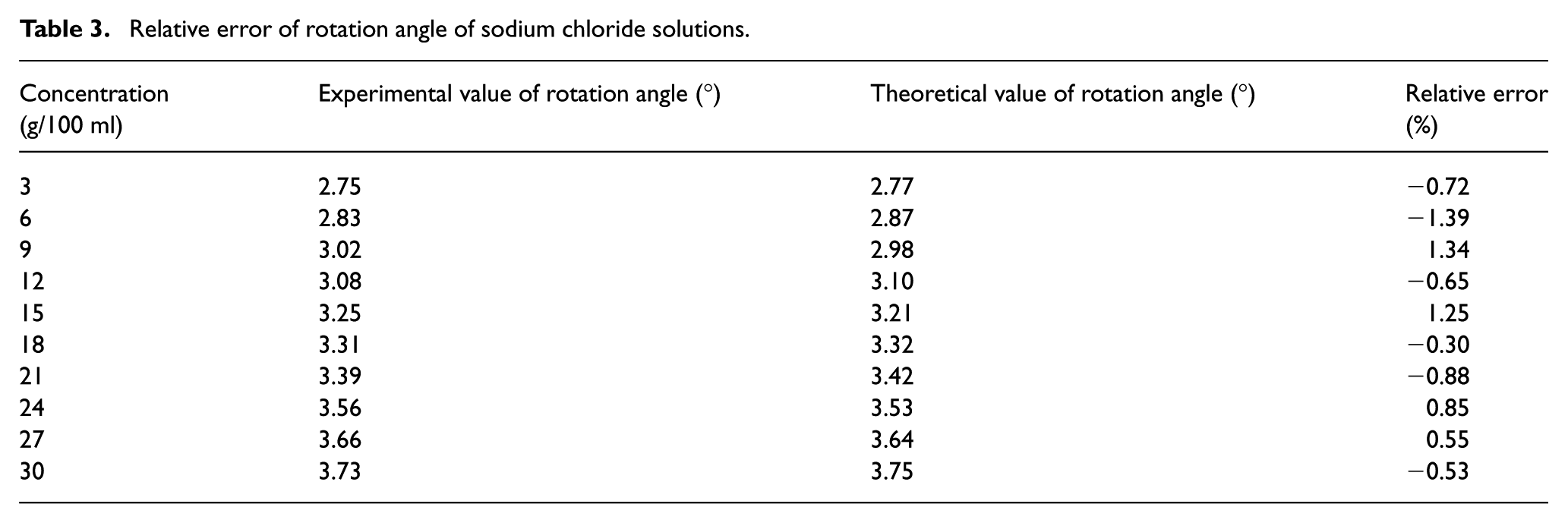
Relative error of rotation angle of sodium chloride solutions.
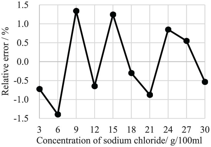
Error distribution of rotation angle of sodium chloride solutions.
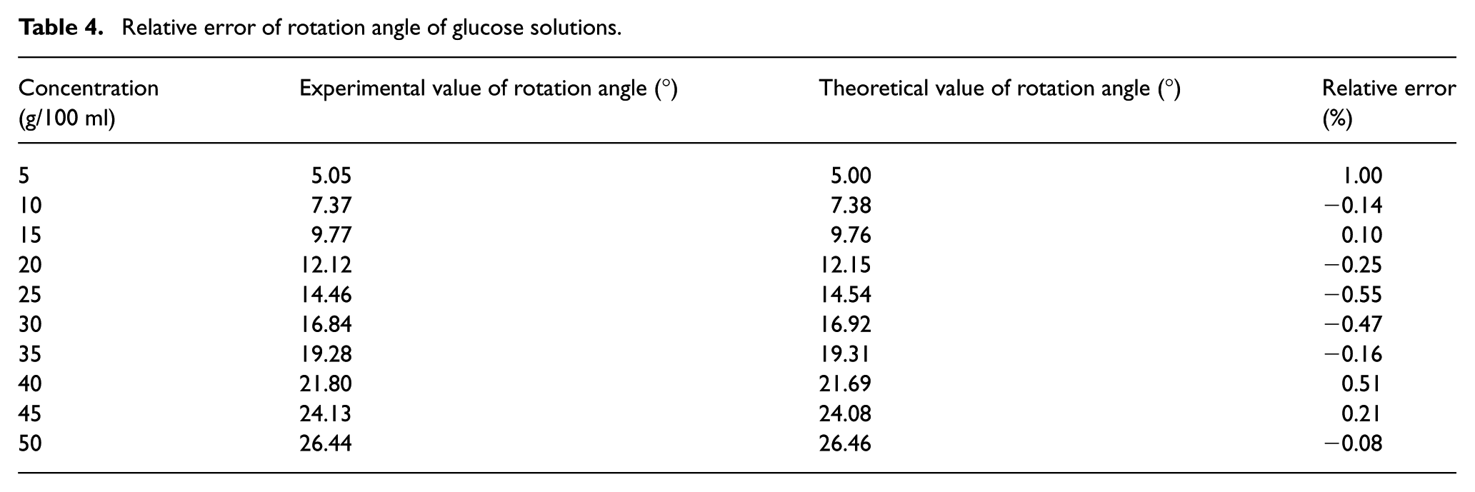
A comparison of experimental values and theoretical values for glucose is shown in Table 4. The corresponding error distribution is shown in Figure 11.
Relative error of rotation angle of glucose solutions.
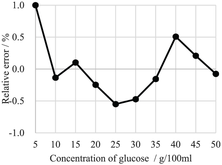
Error distribution of rotation angle of glucose solutions.
Due to the fluctuation of the laser itself, the influence of the external light and the limited resolution of the laser power meter, the measurement results are not identical each time. Taking the 15 g/100 ml sodium chloride solution in the magnetic cavity of Φ1 2mm as an example, 10 measurements were carried out. The standard deviation s can be obtained by
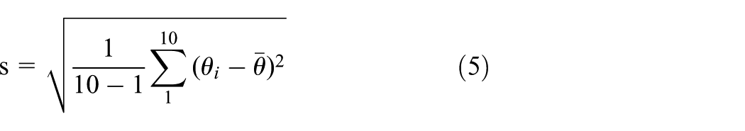
where
Conclusions
In this paper, a new device for the discharge and adjustment of the NdFeB permanent magnet is designed to replace the traditional solenoid magnetic field. We can adjust the magnetic cavity defined as the region enclosed by the permanent magnets so as to change the magnetic field conveniently and quickly by using this device. There is no thermal effect in the permanent magnets, so it has better measurement stability. In the three diameters of the magnetic cavity, the corresponding relationship among the concentration of sodium chloride solution, glucose solution and their magnetic rotation angles are researched. The rotation angle of the solution is proportional to the concentration and increases with the increase of the magnetic induction intensity. We can detect the concentration of solutions using this system based on equations (2) and (3). Compared with the traditional chemical titration method, this method has a shorter measuring time. This method expands the range of materials that can be used in polarimetry and is a non-destructive measurement. So, it is expected to have an excellent use in the industrial production field where the solution concentration needs to be controlled.
In the future, we can take more kinds of solutions as the experimental objects. The method of measuring rotation angle can also be improved to improve accuracy. Furthermore, the arrangement and type of the permanent magnets can be further considered to obtain a much stronger magnetic field.
Footnotes
Declaration of Conflicting Interests
The author(s) declared no potential conflicts of interest with respect to the research, authorship, and/or publication of this article.
Funding
The author(s) disclosed receipt of the following financial support for the research, authorship, and/or publication of this article: This work was supported by the National Natural Science Foundation of China (grant number 51575277).