






Abstract
This paper presents the design and implementation of a fuzzy logic controller using Very High Speed Integrated Circuit Hardware Description Language (VHDL) on a field programmable gate array (FPGA). First, a Sugeno-type fuzzy logic controller with five triangular and trapezoidal membership functions for two inputs and with nine singleton membership functions for one output is examined. The proposed structure is tested with second- and third-order system model using FPGA-in-the-loop simulation via a MATLAB/Simulink environment. Then, for different kinds of fuzzy logic controllers, a new look-up table (LUT) and interpolation-based controller implementation is proposed to eliminate the computational complexity of the primarily designed structure. As a case study, a magnetic levitation system is controlled with an adaptive neuro-fuzzy inference system (ANFIS) trained fuzzy logic controller, then it is simulated and implemented using a LUT-based controller. Finally, we provide a comparison of results.
Introduction
In recent years, real-time applications of various physical system have become increasingly important. The most significant feature expected in real-time applications is high-speed processing. Therefore, the use of devices such as field programmable gate arrays (FPGAs) and graphics processing units (GPUs) that have the ability to process at high speeds are becoming widespread in such applications. FPGAs are programmable integrations that have parallel processing capability and can change the internal structure according to the desired functions and applications. Thanks to this parallel programming capability, FPGAs are used in a wide variety of applications such as extensive analysis of power converters failure analysis in AC motor drives (Aiello et al., 2017), hyperspectral image analysis (Plaza and Chang, 2008), systems that need high-performance computing (Meswani et al., 2013) and vision-based multi-robot tracking problems (Irwansyah et al., 2017).
Some techniques have been presented in the literature for the implementation of a fuzzy logic controller on a FPGA. A fuzzy logic controller is a method that allows the parameters of the system behaviour to be defined with linguistic variables instead of the mathematical model of the system. Owing to this feature, it is often the preferred choice for controlling systems that are nonlinear or have complex mathematical models. Chen et al. (2009) gave details of a digital fuzzy-PID controller design for FPGA, and Aguilar et al. (2014) explained the design and efficient implementation of a Takagi–Sugeno multivariable fuzzy logic controller. A speed control implementation of an induction motor with a FPGA-based fuzzy logic conventional direct torque technique was presented by Krim et al. (2015). The fuzzy logic structure can be implemented in FPGA using Very High Speed Integrated Circuit Hardware Description Language (VHDL). VHDL is the one of the famous languages used for configuring FPGA devices. In particular, there are many studies about creating membership functions and the rule base structure with VHDL. Vuong et al. (2006) described the implementation for a basic fuzzy logic controller with VHDL, Oliveira et al. (2010) showed the design and implementation of a Mamdani-type fuzzy controller using VHDL and Zhang et al. (2010) explained the VHDL implementation of the hybrid fuzzy logic controllers with a FPGA.
Another nonlinear system controlled by fuzzy logic is magnetic levitation (maglev). Maglev is a system that keeps an object in the air using only a magnetic field for support. These magnetic fields are used to counteract gravitational or other accelerations in the same direction. Maglev is a very important control problem because it is a highly nonlinear system and its parameters are uncertain. Thus, many different control strategy have been implemented on it. Zhang et al. (2011) designed a global sliding mode technique that is able to stabilize a linearized system and compared the results with a classic PID controller. A robust sliding-mode-based cascade control approach was proposed for tracking the reference position of a maglev system by Eroğlu and Ablay (2016), and an observer-based feedback controller was designed by Baranowski and Piatek (2012). An adaptive backstepping controller and an adaptive fuzzy backstepping control for a maglev system was examined by Adıgüzel et al. (2018) and Sadek et al. (2017), respectively. A FPGA implementation of the Runge–Kutta model predictive control mechanism was proposed by Iplikci and Bahtiyar (2016). Raygoza-Panduro et al. (2008) have designed a mathematical unit in a FPGA for the implementation of the control of a maglev system. Hamed and Elreesh (2013) presented a FPGA optimized fuzzy controller design for maglev using genetic algorithms.
Most of the earlier FPGA-based fuzzy logic controller design studies have focused on triangular- or trapezoidal-type membership functions, thus their linear structure is more convenient to VHDL code architecture than other nonlinear types of membership functions such as Sigmoid and Gaussian. On the other hand, it is also possible to use the existing memory elements in a FPGA to create look-up tables (LUTs) if the controller structure is suitable for gridding and an interpolation method can also be used to improve the controller output signal. The interpolation -based methodology proposed in the present work can be used not only with linear- but also with nonlinear-type membership functions.
The first part of this study is devoted to the design and implementation of a fuzzy logic controller on a FPGA using VHDL and the simulations are performed with FPGA-in-the-loop (FIL) environment. To do this, the basic structure of a fuzzy logic controller such as membership functions and rule tables are developed with VHDL. Then, these codes are embedded in the FPGA and the FIL block is created via MATLAB/Simulink. To test the designed structure, second- and third-order system models are simulated in both FIL environment and MATLAB Fuzzy Logic Toolbox.
Then, to improve the controller structure for different types of plants, a novel LUT and n-linear (linear, bilinear, trilinear, etc.) interpolation-based method is proposed. To obtain the LUT, an adaptive neuro-fuzzy inference system (ANFIS) is used. The data set that was obtained from a previously implemented nonlinear controller is used for training the ANFIS and an ANFIS-based controller is constituted. A nonlinear system has been selected for the implementation of the controller structure. For this purpose, a maglev system was chosen and the developed ANFIS-based controller is simulated using the nonlinear model of maglev. After that, by gathering the data from the inputs and output of the ANFIS-based controller, the LUT is obtained. As the controller has three inputs, a trilinear interpolation method is used. The LUT-based trilinear interpolation method is written with VHDL and embedded in a FPGA. To test the performance of the controller, FIL simulation and a real-time implementation have been conducted. The most significant advantage of the proposed structure is that as the VHDL code is written at a binary level, one can get rid of some complex mathematical operations such as division and creating membership functions such as Gaussian or Sigmoid.
The rest of this paper is organized as follows. The design and implementation of fuzzy logic control with VHDL is introduced and tested with FIL simulation. After that, a new LUT and interpolation-based controller design is examined. The nonlinear model of a maglev system is introduced and controlled with ANFIS. Then, FIL simulation and a real-time implementation of a maglev system is achieved with a LUT-based controller. Finally, the simulation and experimental results are given.
Classical fuzzy logic controller design with VHDL
Fuzzy logic controllers depend on engineering experience and expert observations. Unlike the conventional controller structure, designing a fuzzy logic controller does not depend on the mathematical model of the system. Therefore, it is convenient for linear and nonlinear systems, even for systems with parametric uncertainty. In a general fuzzy logic control system, there are four basic units as shown in Figure 1: fuzzification, knowledge base, inference engine and defuzzification.

General structure of a classical fuzzy logic controller.
In the fuzzification process, the input variables are converted into a degree of membership by the help of membership functions. In other words, the input values are transformed into linguistic variables. An inference engine manages the data base and the rule base and it decides that the appropriate rules are used. There are several inference methods, but min–max and max–dot product compositions are the most frequently used. In the rule base unit, there are a set of rules that relate to input and output variables of the controller. These rules are simple if–then structures with a condition and conclusion. In the defuzzification process, the resulting fuzzy sets are converted into real values that creates the actual control signal. There are several defuzzification methods in the literature, but the weighted average method is generally preferred when the output membership functions are singleton and it can be easily used with digital platforms.
As fuzzy logic controllers require many computations, FPGAs provide a possible solution owing to their very large-scale integrated circuit technology. Although the most preferred fuzzy logic controller method is Mamdani, it is not suitable for digital platforms. On the other hand, Sugeno-type controllers are computationally more efficient and suitable. The most significant difference between these controller types is the defuzzification methods that produce the final output value. The Mamdani method generally uses slow and complex defuzzification methods whereas Sugeno uses simple numeric methods. Therefore, a Sugeno-type fuzzy logic controller is more suitable for implementation with VHDL.
In this design, error and change of error are selected as inputs for the fuzzy logic controller. In VHDL, these input values are represented with 12-bit binary values since a 12-bit analogue–digital converter (ADC) and a 12-bit digital–analogue converter (DAC) are used in the real-time application of the study. In general, for input membership functions, triangular or trapezoidal symmetric membership functions are selected owing to their linear structures conforming to the VHDL architecture. These types of the membership functions can be stored with two points and two slopes using VHDL. For this representation, the universe of a trapezoidal-type membership function is divided into four segments as shown in Figure 2. For each part, the slope values and the membership values are calculated using (Anand and Tyagi, 2012)


A trapezoidal membership function.
The fuzzy logic controller is designed for two inputs and five input membership functions for each input are considered, two trapezoidal and three triangular membership functions are used as shown in Figure 3. They are named as negative big (NB), negative medium (NM), zero (Z), positive medium (PM) and positive big (PB). The numbers of input membership functions are obtained by a trial and error method to stabilize the system.
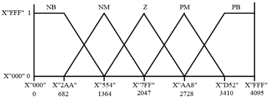
Input membership functions.
To calculate the membership values for each candidate input using the formulae given in (1) and (2), an array whose size is equal to the membership function value is created. Since the candidate input value only intersects at most with two membership functions, the other elements of the array are assigned zero. Hence, the result of the fuzzification process is a two-dimensional array for two inputs and both arrays have five 12-bit vectors. In a general fuzzy logic controller, the universe of discourse is ranged as
The next process in the fuzzy logic controller is the inference engine. After the degree of membership values are determined in the fuzzification interface, the rules that decide which action should be taken is used at this stage. The rules are written with the technique called a min–max interface. They take the form of an if–then statement such as “If x=a and y=b then z=c”. The rules determine the condition of the system at a given point using linguistic variables and fuzzy sets. The number of rules depends on the number of input membership functions. Since five membership functions are selected for each input there are 25 rules written as shown in Table 1. Here, a two-dimensional and symmetrical rule table that is commonly used in fuzzy logic applications is preferred.
The rule table.

The output of the inference engine gives the fired output membership functions. For this study, the output membership functions are selected as singleton, which reduces the complexity of VHDL code and they are named negative very big (NVB), negative big (NB), negative (N), negative small (NS), zero (Z), positive small (PS), positive (P), positive big (PB) and positive very big (PVB) as shown in Figure 4. There is one rule for NVB, two rules for NM, three rules for N, four rules for NS, five rules for Z, four rules for PS, three rules for P, two rules for PB and one rule for PVB as shown in Table 1. The number and range of singleton-type output membership functions are determined so that all rules would be active. However, it can be increased or decreased in accordance with the application and FPGA calculation capability.

Output membership functions.
In the defuzzification interface, the grades of nine output membership functions are determined. The final crisp output value is calculated by the weighted average of all contributions of the output sets as follows:

The main advantage of this method is its computational simplicity. Here
To test the designed controller, a FIL design environment is used. FIL is a kind of hardware-in-the-loop (HIL) simulation that is used to test the controller design. It shows the controller responds in real time. FIL simulation provides the capability to use a MATLAB/Simulink design and a simulation environment for testing the designed controller that can be written with any hardware description language (HDL) on real hardware. Here, the controller is integrated on the FPGA chip, whereas the model under control is implemented in MATLAB/Simulink. One advantage of this technique is that it is possible to design some operations that are difficult to implement on a FPGA such as the division process in the MATLAB/Simulink.
In this study, the controller code is written with VHDL with the help of the Quartus Prime 15.1 programming platform and uploaded to Altera DE2-115 FPGA Development and Education Board to test with FIL simulation. In Simulink, a FIL block that represents the HDL code is generated by using VHDL file, then synthesis, logical mapping, place and route, programming file generation and the communication channel are provided with the connection between Simulink and Quartus. Finally, the design is loaded to a FPGA. FIL provides the communication channel for transmitting and receiving data between Simulink and the FPGA via an Ethernet connection.
The designed controller is tested by using second- and third-order linear system models given in

and

respectively. The same controller structure is designed with MATLAB Fuzzy Toolbox to provide a comparison and the simulation results demonstrated that the controller ability is satisfactory for linear systems.
The reference signals are selected as step and sinusoidal functions as shown in


and the results are demonstrated in Figures 5 and 6, respectively.

Second-order system outputs for (a) step input and (b) sinusoidal input.

Third-order system outputs for (a) step input function and (b) sinusoidal input function.
As can be seen in Figures 5(a) and 6(a), for the step input, there is no overshoot and the settling time values are sufficiently close to each other and one can easily say that after a short transient time, both output values converge to the desired reference value. For the sinusoidal input given in Figure 5(b) and 6(b), the output signals track the input signal successfully. The small differences from the outputs stem from the real-time data acquisition between MATLAB/Simulink and the FPGA board. Similar results are also discussed in Akkaya et al. (2017).
LUT-based controller design for FPGA
For different plants, the proposed controller structure explained above can be insufficient owing to the type of membership functions. In some cases, the shape of the membership functions can be changed or the rule table can be modified. However, implementing different types of membership functions such as Gaussian or Sigmoid requires more computational resources in a FPGA. In addition, to use FPGA as a stand-alone controller in a system, a division operation must somehow be achieved. Moreover, in some controllers the defuzzification section requires excessive calculations. To overcome this kind of the difficulties a novel LUT and interpolation-based method is proposed. First, with the help of an experimental study, the upper and lower limits of the controller inputs and output are determined. Then, a data set is created using these range values. Finally the controller output that correspond to the current output value is obtained by applying the n-linear interpolation method to this data set.
In this study, trilinear interpolation method is used for three input values. Trilinear interpolation is a computational process of linearly interpolating points within a three-dimensional box given values at the vertices of the box (Bai et al., 2012). The interpolation process actually correspond to three linear interpolations along the coordinate axes, x, y and z, respectively. As shown in Figure 7(a) the origin of a unit cube is denoted as

(a) Eight corner points and (b) trilinear interpolation.
Let

be the differences between the target
The first step is interpolated along the x-axis by pushing the face of the cube defined by

where
Then, the interpolation is performed along the y-axis while pushing from

Finally, these values are interpolated along the z-axis through

To show how this method can be implemented with VHDL, a simplified block diagram with three inputs is given in Figure 8. As shown in Figure 8, the three inputs are supposed to have 12-bit resolution, the LUT has

Block diagram of the LUT and interpolation-based controller.
Experimental study: maglev system
The maglev system shown in Figure 9 is a nonlinear system that consists of an electromagnetic coil, an infrared transmitter and a sensor. The vertical ball position can be controlled with the electromagnetic force by adjusting the current that is obtained by applying a controlled voltage across the electromagnet terminals.

Maglev system.
The mathematical model of the maglev system is

where m is the mass of the ball, x is the vertical distance from the electromagnetic coil, k is the magnetic force constant, i is the current of the electromagnetic coil and g is the gravitational constant (Yadav et al., 2017). The parameters of the dynamic model is given in Table 2.
Parameters of dynamic model.

Fuzzy logic controller with ANFIS
ANFIS is a prominent neuro-fuzzy model, and has produced robust results among other fuzzy inference systems, as it is more flexible, adaptive and effective on highly nonlinear complex problems (Talpur et al., 2017). ANFIS is constructed by partitioning of the input–output data into rules.
Here, the position of the ball (x), the difference of ball position and reference ball position (

ANFIS-based controller simulation results for reference and ball position.

ANFIS-based controller simulation results for the current signal.
FIL simulation for the maglev system
In this section, the controller obtained above is implemented by using a LUT with trilinear interpolation. To evaluate the performance of the proposed controller structure, FIL simulation is conducted using the maglev system model. Inputs of the system are reconstructed to be suitable with binary values that would be obtained from the existing ADC and the output of the controller is a binary value that will be applied to a DAC whose output is proportional to the desired current. For the inputs, upper and lower boundaries selected are given in Table 3. These boundaries and the corresponding ADC conversion values are chosen to simplify the binary operations and maximize the resolution of the operation interval. Since division operation is not easy in VHDL, division with power of two is preferred, which can be achieved by just shifting the binary value. In the previous section, a simple representation of LUT and trilinear interpolation is given in Figure 8. This type of selection causes the interpolation process to have a certain upper bound. The value of “3968” is the threshold of the highest selection value where the five most significant bits are “1”. Interpolation is not done beyond this threshold, which is also not expected. However, when such an input value arrives at one of the inputs on the designed controller, bilinear interpolation is switched on and only the interpolation operation for the corresponding input is disabled. The consistency of the output values obtained at this point is not impaired.
The range values of controller inputs.

The generated data set is represented by 12-bit binary numbers. As mentioned above the values can be selected with a 15-bit value, which consists of the most significant five bits received from three inputs. As a result, LUT is created as a one-dimensional array with 32768 values. Then, the trilinear interpolation method is written with VHDL. All the code is embedded in a FPGA and the FIL simulation is conducted via MATLAB/Simulink environment. Since the real experimental setup expresses metric values with volts, same conversion blocks are used to keep the controller diagram to be similar to the real one. The block diagram is given in Figure 12 and the simulation results are given in Figures 13 and 14. For the same reference signal given in the ANFIS-based simulation, the reference trajectory is tracked satisfactorily as can be observed from Figure 13

Block diagram for FIL simulation.

FIL simulation results for reference

FIL simulation results for the current signal.
Real-time implementation
For real-time implementation, the proposed controller structure is applied to a maglev setup. In the previous section, the plant model given in (12) is used in the simulation belonging to the related setup. This setup consists of a ball, an electromagnetic coil, a measurement unit, a coil current driver and the required circuits with a power supply. The measurement value that can be read in Volts expresses the ball position which is approximately linear. However, to be able to use this value, some gain and offset conversion circuit has been assembled. In addition, the coil current driver requires its input in Volts and needs values below 0 V. For this purpose, an output stage with a symmetrical supply is also added to the DAC circuit output. FPGA DE0 Nano-Board contains an ADC128S022 lower power, 8-channel, 12-bit ADC, a MPC4922 12-bit DAC and a designed measurement circuit are used. The nominal values of the maglev system are given in Table 2. The vertical position of the ball is measured with an in-built analogue infrared sensor and the data is transferred to measurement circuits that produce the controller input parameters. The controller output is transferred to the system through the DAC module attached to a suitable conversion circuit as mentioned above. The block diagram that shows data flow is shown in Figure 15 and the experimental study results are given in Figures 16 and 17. For the sinusoidal reference signal that is applied in the ANFIS-based simulation and FIL simulation, the ball position tracks the reference signal satisfactorily with negligible noise. The experimental setup is shown in Figure 18.

Block diagram for real-time implementation.

Experimental results for reference

Experimental results for the current signal.

Experimental setup.
To compare both the simulation and the application results, the root mean square (rms) of error data sets are calculated as new terms. As a result, the rms error value in the simulation part is obtained as
Conclusion
In this study, a fuzzy logic controller implementation in a FPGA under different conditions has been examined. In the first part, a simpler fuzzy logic controller with triangular and trapezoidal input membership functions was implemented. The designed controller which is coded with VHDL has been examined on linear systems thanks to FIL simulation. The designed structure compared with the same controller designed a MATLAB Fuzzy Logic Toolbox and satisfactory results are obtained. Here, FIL simulations allow hardware tests which deploy the design on target and observe the performance of the design under real-life conditions. The advantage of this techniques is that it is very useful to test the controller function with a simulated process before the controller is applied to the physical process. Then, an implementation of a complex fuzzy logic structure with LUT and n-linear interpolation-based design structure is shown. Next, a constructed fuzzy logic controller based on ANFIS is simulated with MATLAB and data set is created using ANFIS-based controller results. Further, a novel design structure has been proposed using the data set and estimated via LUT and tested with FIL. At the end, the constructed controller structure is applied on a real maglev setup and the results are given. In the study, it has also been noted that the parameters of the maglev setup are changing based on magnetization of the ball and temperature of the coil and its driver. As future work, we plan to attach an adaptive ability to the current LUT-based controller over a FPGA.
Footnotes
Declaration of Conflicting Interests
The author(s) declared no conflict of interests with respect to the research, authorship, and/or publication of this article.
Funding
The author(s) received no financial support for the research, authorship, and/or publication of this article.