
Abstract
Currently, space robots such as planetary robots and flexible-link manipulators (FLMs) are finding specific applications to reduce the cost of launching. However, the structural flexible nature of their arms and joints leads to errors in tip positioning owing to tip deflection. The internal model uncertainties and disturbance are the key challenges in the development of control strategies for tip-tracking of FLMs. To deal with these challenges, we design a tip-tracking controller for a two-link flexible manipulator (TLFM) by developing a sampled-data extended state observer (SD-ESO). It is designed to reconstruct uncertain parameters for accurate tip-tracking control of a TLFM. Finally, a backstepping (BS) controller is designed to attenuate the estimation error and other bounded disturbances. Convergence and stability of the proposed control system are investigated by using Lyapunov theory. The benefits (control performance and robustness) of the proposed SD-ESO-based BS controller are compared with other similar approaches by pursuing both simulation and experimental studies. It is observed from the results obtained that SD-ESO-based BS Controller effectively compensates the deviation in tip-tracking performance of TLFM due to non-minimum phase behavior and model uncertainties with an improved transient response.
Keywords
Introduction
Nowadays, space robots, planetary robots and flexible robots have been developed and utilized in satellite, aerospace and space industries. This flexible-link manipulator (FLM) is very advantageous in terms of lightweight, reduced overall cost and low energy consumption in transportation, the higher payload carrying capacity, more maneuverable and operational speed. However, the structural flexible nature of the FLM’s arms and joints lead to inaccuracy in tip positioning as compared with a rigid manipulator (Subudhi and Pradhan, 2016).
Over the last three decades, control of FLM has been an active research area. A good review on control of FLMs is found in Lochan et al. (2016); Sayahkarajy et al. (2016); and Castillo-Berrio et al. (2015). Owing to a nonlinear and non-minimum phase behavior coupled with model uncertainties and disturbances, control of such manipulator posses a challenging task.
In the flexible manipulator, improving tip-tracking performance and an accurate dynamic model of the system is necessary, which implies that dynamics of both rigid and flexible nature of the links should be represented accurately (Tokhi et al., 2000). It may be noted that due to distributed link flexure, infinite number of flexible modes are necessary to describe the dynamics of an FLM, that is, its dynamic model is infinitely dimensional( Khairudin et al., 2010). However, it is necessary to obtain approximate dimensional model of FLM for designing a controller with finite dimension.
Dynamics of a two-link flexible manipulator (TLFM) exhibit non-minimum phase behavior and design of control strategy for tip-tracking control of this system is very difficult due to unstable internal dynamics (Chen et al., 2012). Many control schemes have been developed to solve this difficulty of tip-tracking control of the TLFM. Generally, tip-tracking control schemes are divided into model-based and non-model- based methods. Non-model-based methods are simpler and easier to implement than the model-based methods. In recent years, many non-model-based control methods have been developed to solve the tip-tracking control problem of the TLFM, for example, composite control (Lochan et al., 2018a), sliding mode control (Lochan et al., 2018b), robust control (Mohamed et al., 2016), adaptive control (Pradhan and Subudhi, 2012, 2014; Subudhi and Pradhan, 2016), intelligent control (Agee et al., 2014; Cheng, 2015), observer-based control (Zhang et al., 2017), and so forth. The above controllers handle tip-tracking issue under both kinematic and dynamics uncertainties. However, owing to the link flexure, the dynamics of FLM is a distributed parameter system, that is, an infinite number of flexible modes are needed for the modeling. However, for realization of the controller, a finite dimensional model is necessary. Hence, it is necessary to truncate the higher order flexible modes. However, this neglect of higher order flexible modes gives rise to uncertainties in the dynamics. We consider these as disturbances and un-modeled dynamics that are the major source of uncertainty in the dynamics of TLFM. Hence, designing a suitable controller for real-time application for a TLFM that exhibits high nonlinearity, uncertainties and disturbances is still a challenging task in real-time, which motivates us to attempt this in this paper.
In order to handle the model uncertainties and disturbances associated with TLFM, a linear quadratic regulator (LQR) controller (model-based) has been used by Xu and Ritz (2009) and Etxebarria et al. (2005) for the flexible dynamics. However, in Etxebarria et al.’s (2005) technique, a larger overshoot occurs that causes inaccurate tip-tracking performance in FLM. Furthermore, backstepping (BS) control (non-model based) is adopted by many researchers, to handle uncertainties and disturbances in nonlinear systems. BS control is one of the most powerful control techniques that ensures the stability of the system as each control law is derived by employing Lyapunov criterion. In addition, the backstepping control approach shows several advantages such as follows. In the situation when uncertainty information is unavailable, a controller can be designed to reduce on-line calculation (Jamil et al., 2014). The backstepping approach is also used for tip-tracking control of a single-link flexible robot in Zhu et al. (1997). In Jong and Lee (1998), the backstepping control provides excellent tracking of tip position for a flexible joint manipulator. A robust regulator for accurate tip-tracking for flexible joint robots using integrator backstepping approach is proposed by Abouelsoud (1998). Adaptive sliding control for a single-link flexible-joint robot with external noise and modeling uncertainties is developed in Huang and Chen (2004). Backstepping control using a genetic algorithm for single link flexible joint manipulator is proposed in Sahab and Modabbernia (2011). Backstepping control is applied for trajectory tracking control of TLFM in Lochan and Roy (2016). Control of two-link flexible manipulator using a backstepping controller with an extended state observer has been presented in Yang et al. (2015). However, most of the literature deal with only tip-tracking control of a single-link flexible manipulator (SLFM). Only a few works have been reported on trajectory tracking control of TLFMs. In view of successful applications of backstepping control of SLFM, we extend the approach to design a tip-position tracking controller of a TLFM in this work.
Further, nonlinearities, unmodeled dynamics, unmeasurable noise and so forth, are most often considered as major uncertainties in TLFM. Due to these uncertainties, partial state vector or a non-uniform signal is usually received by the controller (Tian et al., 2016). In view of estimating uncertain parameters, a state observer needs to be designed. The extended state observer (ESO) is designed to estimate uncertainties by lumping these into as an extended state. In Yang et al. (2015) and Sahu and Patra (2016), a continuous-time ESO has been developed on the basis of unmodeled dynamics of FLM. However, uncertain parameters approximated by a continuous-time ESO are more complex and erroneous. Moreover, an ESO often needs to be implemented digitally in various computer-based control applications. Hence, it would be appropriate to use digitally implemented ESO. The digital implementation of ESO has also received considerable attention. In Miklosovic et al. (2006), various digital approximation techniques of ESO are studied and compared. The discrete-time ESO is implemented for an uncertain single-input-single-output (SISO) system in Huang et al. (2015). The discrete ESO-based repetitive control for servo motor is presented in Sayem et al. (2016). The discrete ESO has been developed to approximate the uncertain parameters for a servo system (Wang et al., 2017) and non-linear system (Tian et al., 2016). In most of the existing works, discrete ESO is designed based on a direct discretization of the plant model. Inspired by this line of research, we propose design of a sampled-data extended state observer (SD-ESO) to estimate the uncertain parameters that will be used for designing tip-tracking controller for a TLFM to achieve accuracy.
In this paper, we intend to develop a unified tip-tracking control algorithm for flexible manipulator by employing backstepping control technique together with designing an SD-ESO for estimating disturbances. The contribution of the paper is as follows. A SD-ESO is developed for simple, fast and accurate estimation of uncertainties present in TLFM ensuring its convergence, and SD-ESO-based BS controller is designed for tip-tracking control of TLFM. Also, the tip-tracking performance of the proposed SD-ESO-based BS controller is compared with that of linear quadratic regulator (LQR) controller (model based) (Xu and Ritz, 2009), BS controller (non-model based) (Lochan and Roy, 2016) and ESO-based BS controller (Yang et al., 2015).
The rest of the paper is organized as follows. In the next section, the dynamic model of TLFM is provided, and the control problem is formulated. Then, the design and convergence analysis of the proposed SD-ESO-based BS controller are presented. Simulation and experimental results with discussion are presented, followed by conclusions.
Preliminaries and problem formulation
Dynamic model of TLFM
In a FLM, due to distributed link flexure, the positioning and tracking of the tip are very difficult. We assume that motion of the TLFM in the horizontal plane. The links are assumed to have uniform material properties and constant cross-sectional area (Morris and Madani, 1997). The schematic diagram of a TLFM is shown in Figure 1, where

Schematic diagram of a TLFM.
The dynamics of a flexible manipulator system exhibits a non-minimum phase characteristics when the tip position is taken as the output. The actual output vector
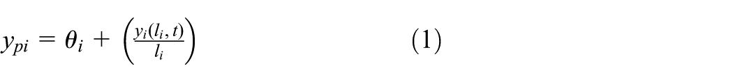
where,
The dynamics of TLFM can be derived by applying the Euler-Lagrangian principle using Assumed Mode Method (AMM). The dynamics of TLFM given in Pradhan and Subudhi (2014) is given by
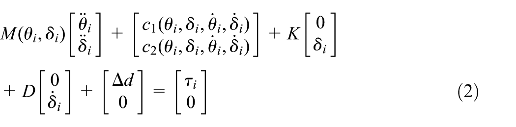
In (2), M is a positive definite symmetric inertia matrix,
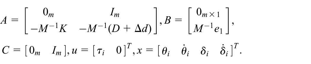
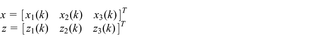
The dynamics of TLFM (2) can be rewritten in state space form as follows
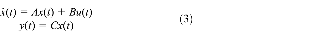
where,
The discrete time approximation of

where, T is the sampling time and
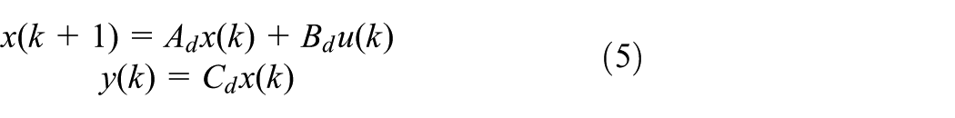
where,
The structure of the proposed BS with SD-ESO-based control is shown in Figure 2. Given the nonlinear FLM system with uncertainties, the objective is to find a control input
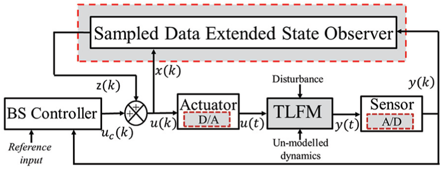
Structure diagram of the proposed BS with SD-ESO.
It is necessary to design a control scheme for a closed-loop system (3) such that the output trajectory
Sampled-data ESO design and convergence analysis
The dynamics of the TLFM (2) is used in the design of the SD-ESO. Here, SD-ESO is developed to estimate uncertainty such as disturbance and un-modeled dynamics. In this section, the subscripts of the variables in (2) are neglected for simplification. From the Appendix, (2) can be rewritten as


From (7), one obtains

Substituting (8) into (6), gives
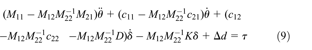
Equation (9) can be written as

The discrete-time representation of (10) is rewritten by considering
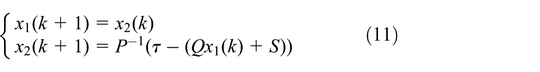
In (11), considering
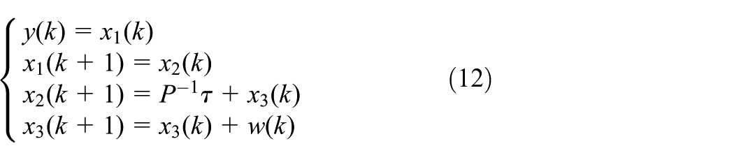
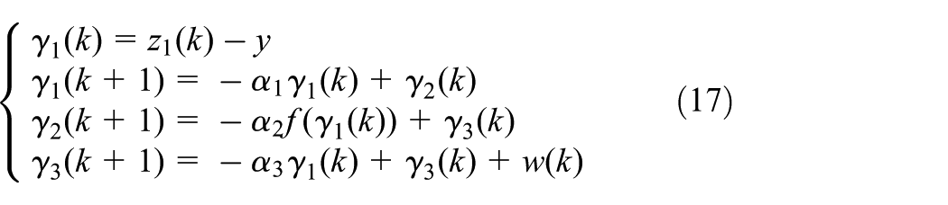
Using (12), SD-ESO is designed, in the similar manner as adopted for continuous-time ESO development
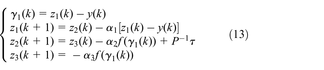
where,
The observer gains
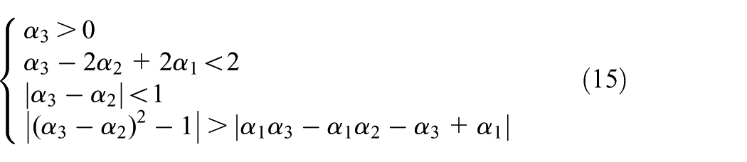

for all
where,
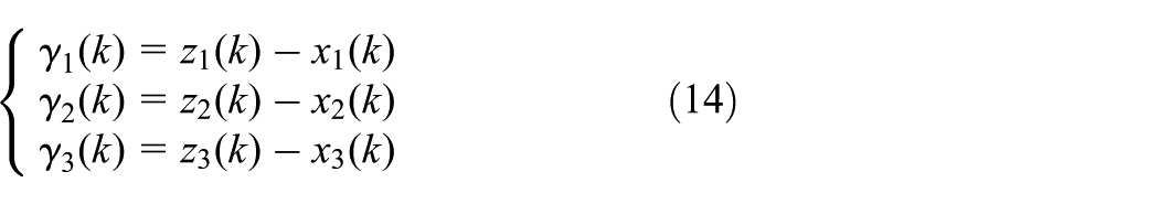
Using (17), the observation error dynamics is given by

where

The eigen polynomial of G is given by

where,
Define a candidate Lyapunov function as

Then
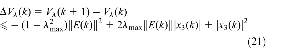
and

Then,
So, the observation error
Convergence analysis of SD-ESO
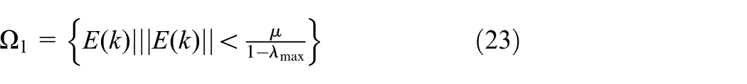
The Self-Stable Region (SSR) method proposed for the uncertain system in Huang and Han (1999) is used for convergence analysis of the closed-loop error system (17).
where
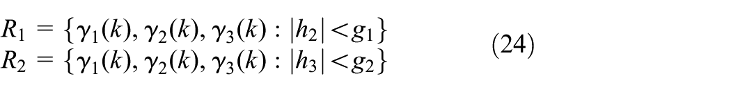
and

and

Defining a continuous positive definite function as
Hence, the trajectories
that is, the observed states

Taking the time derivative of
As
So, the trajectories of
Through the analysis of Theorem 2 and Theorem 3,
Design of BS controller and stability analysis
This section presents the design of three-stage BS controller for accomplishing effective tip-tracking of TLFM. In the BS design, the uncertain parameters of (11) are identified repeatedly as pseudo-control inputs of lower dimension subsystem of the entire system. The structure of the proposed three-stage backstepping control algorithm is shown in Figure 3.
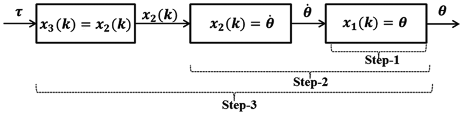
Structure of three-step BS control algorithm.
The control objective is set as follows. The states,

where
that is,
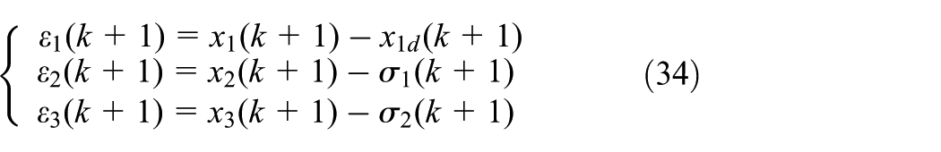
To achieve the above control objective, the error variables can be defined as
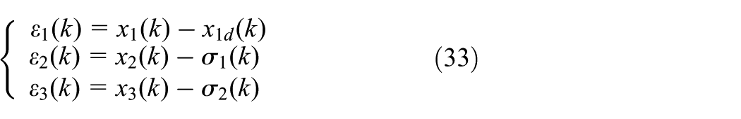
where,
The design steps for BS controller for the system (12) are given below.

Then
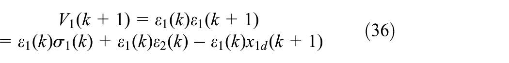
Virtual control is designed as

If the

Then
To realize

Then


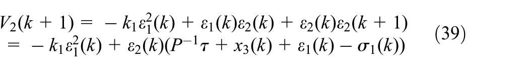
Then
Virtual control is designed as
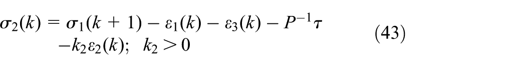
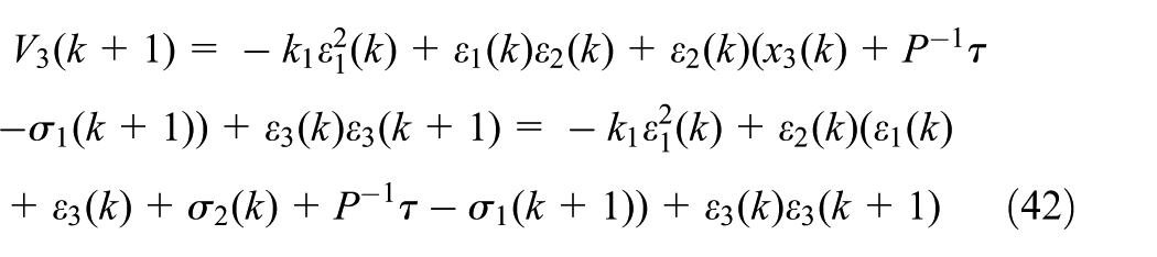
is the constant design factor. Rearranging (42) using (43) gives
To realize

from (43), control law can be expressed as

assume
Stability analysis
To prove the boundedness of closed-loop system, the following assumption and theorems are useful.

where,

Then, we have
and,

Then

This means that the tracking error
So, the obtained tracking error is UGB.
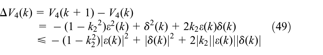
Consider uncertain term

The boundedness of TLFM is established by applying the following theorem.
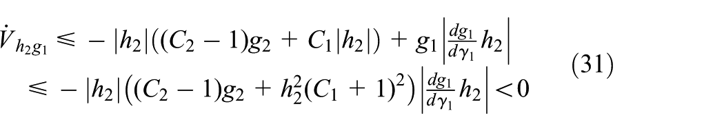
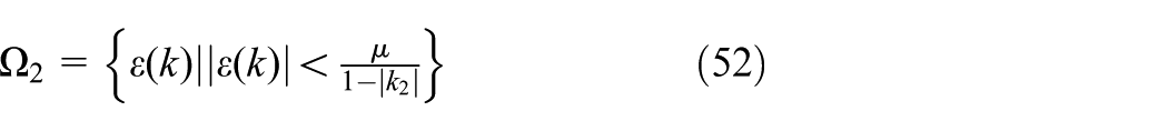
Combining (53), (54) and (55), the closed loop system is given
with the condition given in
Simulation results
The simulations have been carried out in MATLAB/SIMULINK® simulation platform to verify the performance of the proposed SD-ESO-based BS controller applied to TLFM. The physical parameters of TLFM considered for simulation and experimental studies of TLFM are given in Table 1. The Mean Absolute Errors (MAE) and the Mean Square of Errors (MSE) are used as quantitative measures for comparing the performance of the proposed scheme, which is defined in (57) and (58), respectively. Also, Standard Error of Mean (SEM) (59) is used for statistical verification of estimation errors.


Physical parameter of link-1 and link-2.
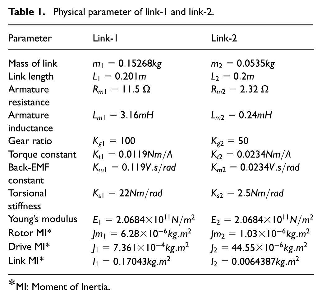
MI: Moment of Inertia.
Model validation
In this section, the simulations are carried to validate the dynamic model of the studied TLFM given in (3). Open loop responses of the TLFM are obtained through both simulation and experiments. Sinusoidal torque inputs with 20° amplitude and 0.1 Hz frequency are applied to the TLFM model. Figure 4 and Figure 5 show the simulation and experimental hub angle responses, and error between these for link-1 and link-2, respectively. MAE and MSE are calculated from error curves obtained from Figure 4 and Figure 5, and the same are listed in Table 2. It is observed from Figure 4 that the hub angle response of link-1 has a maximum and minimum joint position amplitudes are 20° and −10°, respectively. Link-2 hub angle response is shown in Figure 5, from which it is observed that the hub angle response has a maximum amplitude of 20° and minimum amplitude of −19°. It is also observed from Figure 4 and Figure 5 that the error between the simulation and experimental response of the dynamic model is maintained within a small range in dynamic process. The results indicate that the derived dynamic model of TLFM proves to be an efficient model to describe the physical TLFM.
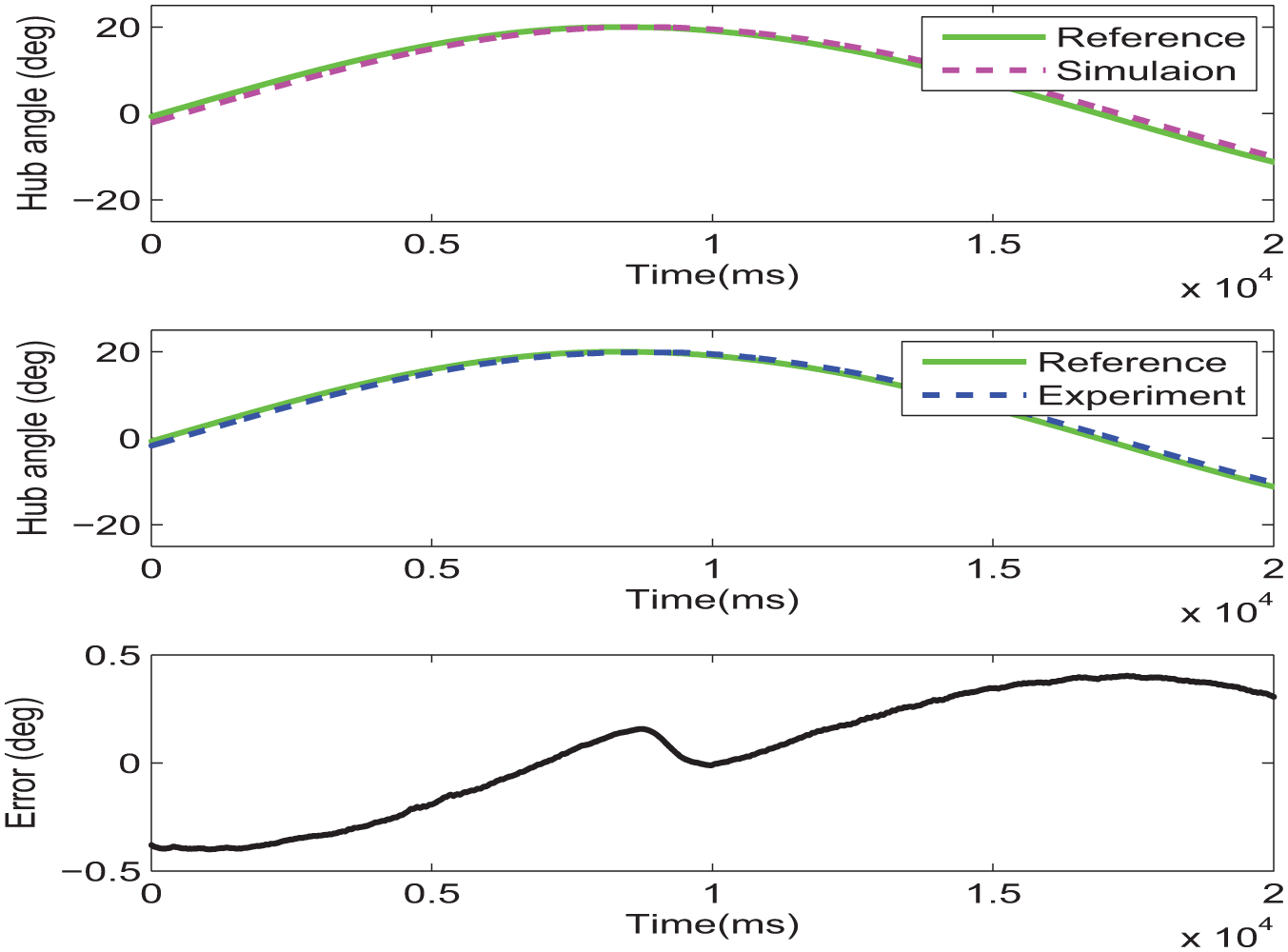
Link-1 hub angle response and error.
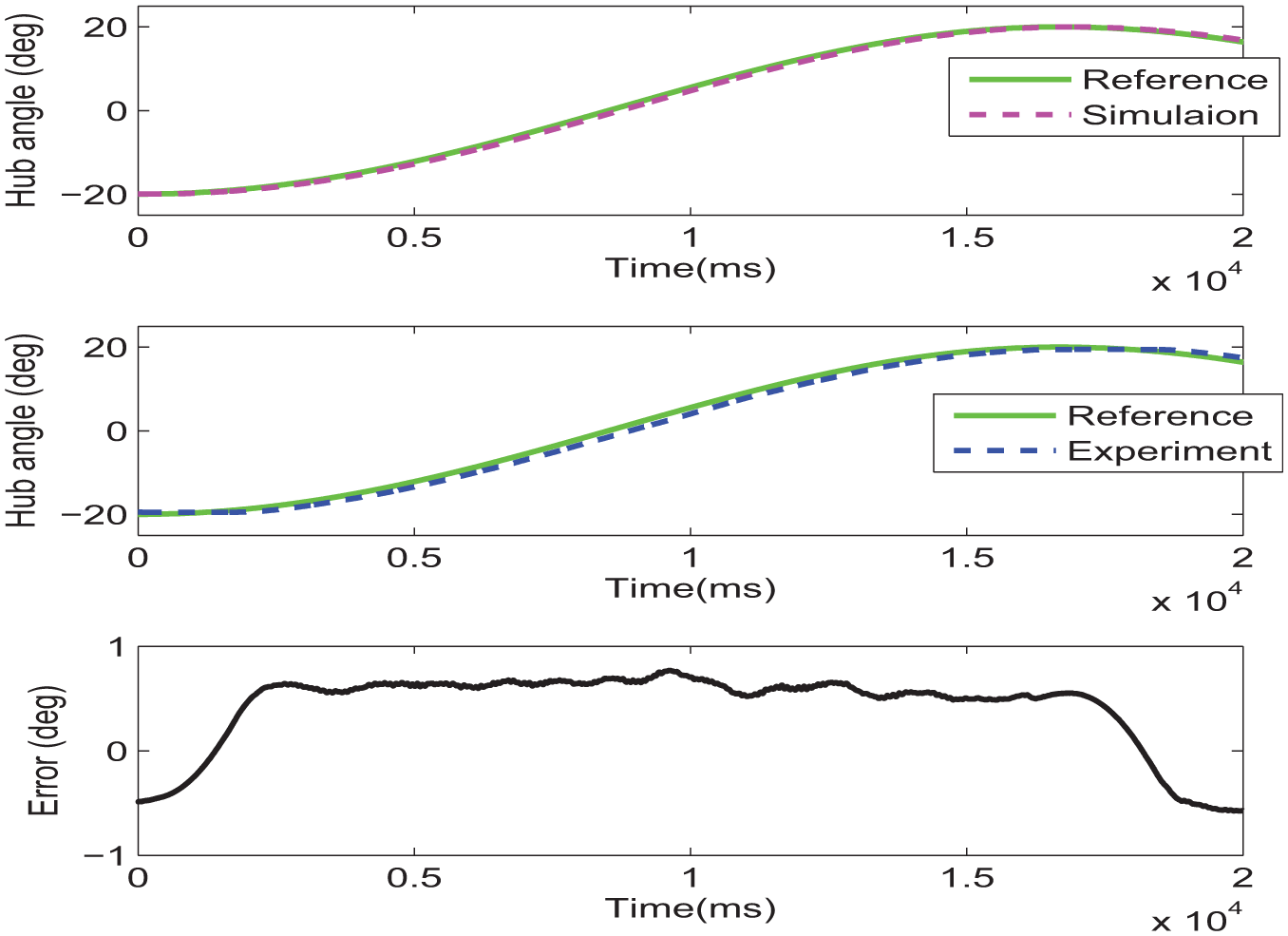
Link-2 hub angle response and error.
MAE and MSE for hub angle response.

Tip-tracking performance
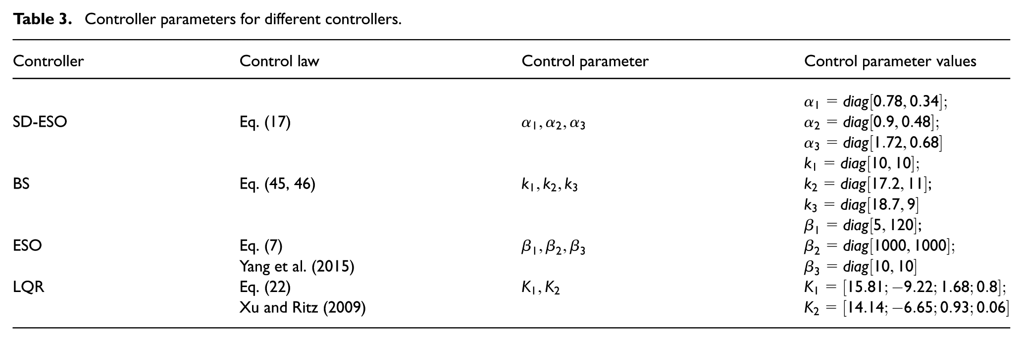
Sinusoidal signals given in (60) are considered as desired trajectories for both the links to investigate the tip-tracking performance. Table 3 listed the control parameters with their values.

where,
Controller parameters for different controllers.
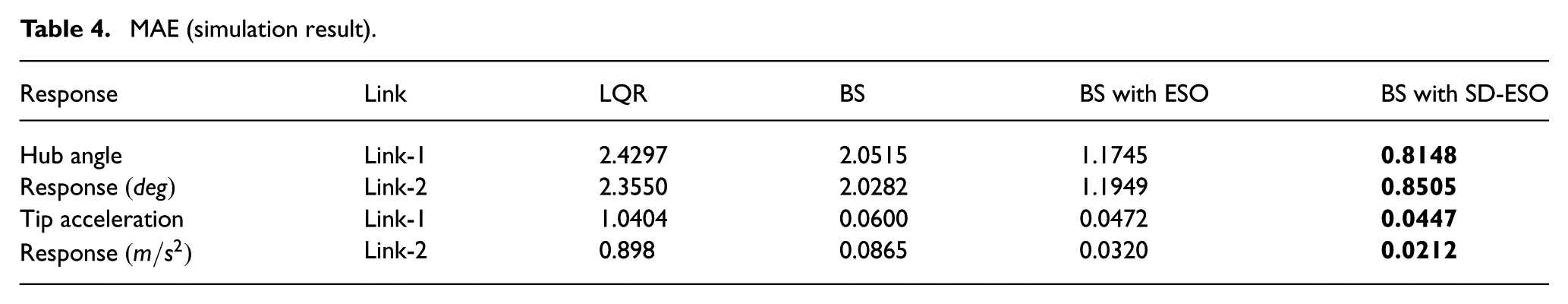
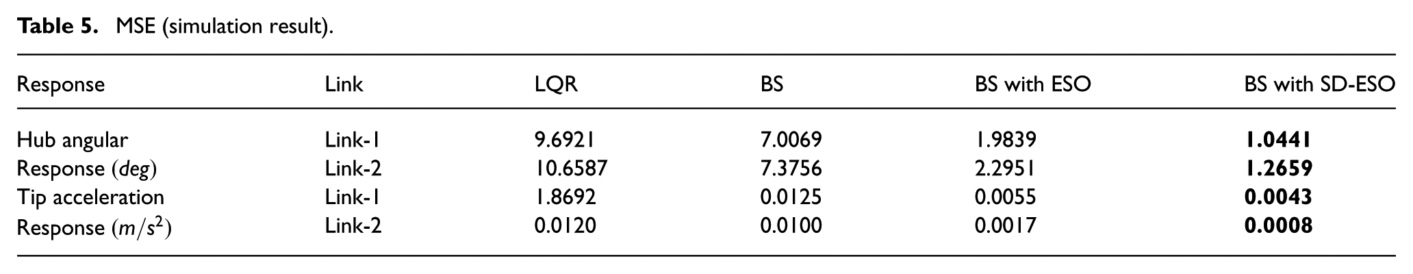
The tip-tracking performance of link-1 is shown in Figure 6. Similarly, Figure 7 shows the tip-tracking performance of link-2. Quantitative metrics (MAE and MSE) are calculated form the response curves obtained from simulation studies of LQR, BS, BS with ESO and BS with SD-ESO, and the same are listed in Table 4 and Table 5. It is observed from Table 4 and Table 5 that MAE and MSE for BS with SD-ESO are lower than that obtained for BS with ESO.
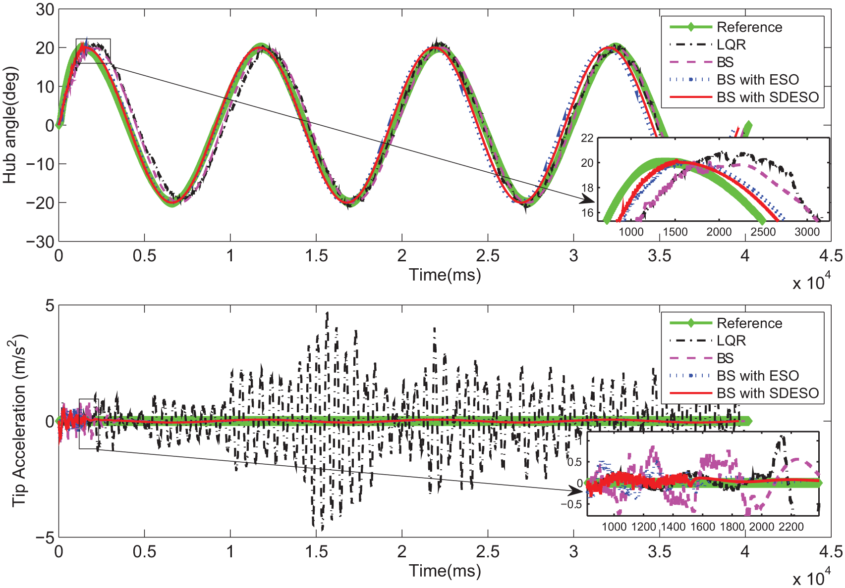
Tip-tracking and estimation of link-1.
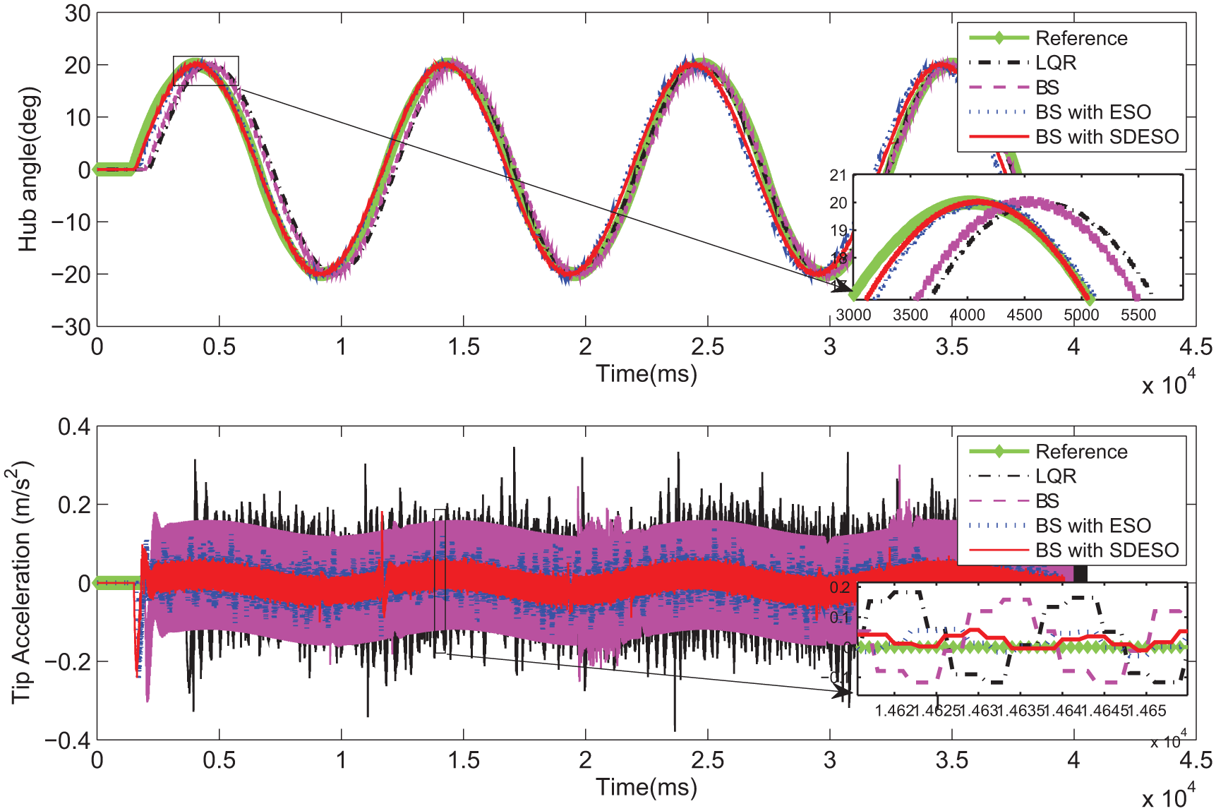
Tip-tracking and estimation of link-2.
MAE (simulation result).
MSE (simulation result).
Tip-tracking (estimation) error (simulation result).
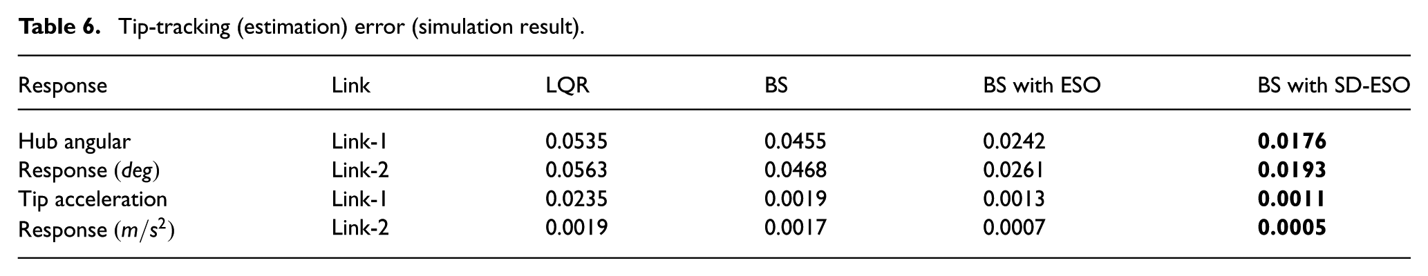
Figure 8 shows the tip-tracking error profiles for link-1, from which it is observed that there is a maximum tip deflection error of 6.5° in case of LQR, 5.4° in case of BS controller, 2.7° in case of BS with ESO, but BS with SD-ESO yields the minimum tip deflection error, that is, 1.6°. The tip acceleration error of link-1 is 4.6
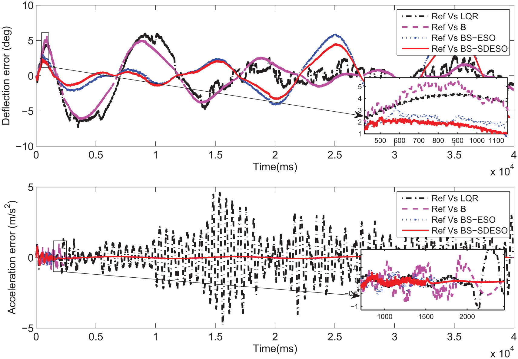
Tip-tracking (estimation) error of link-1.
Figure 9 shows the tip-tracking error profiles for link-2. From Figure 9, it is observed that the maximum tip deflection error is 9.2° in case of LQR, 7.8° in case of BS controller, 3.9° in case of BS with ESO, whereas in case of BS with SD-ESO yields minimum tip deflection error amplitude of 2.5°. The tip acceleration error of link-2 is 0.32
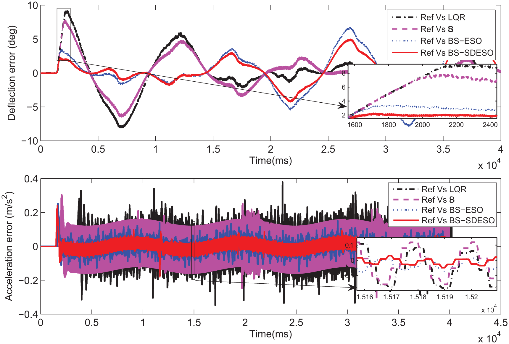
Tip-tracking (estimation) error of link-2.
Figure 10 and Figure 11 show the torque profiles generated by LQR, BS, BS with ESO, and BS with SD-ESO for hub 1 and 2, respectively. It is observed from Figure 10 and Figure 11 that the torque generated by BS with SD-ESO is smooth compared with LQR, BS, and BS with ESO with maximum amplitude of 0.5 Nm and 0.3 Nm, respectively. It is observed from Figure 6–Figure 11 that, the proposed BS with SD-ESO enables tracking of the desired trajectories with minimum tracking error resulting in better tip-tracking performance.
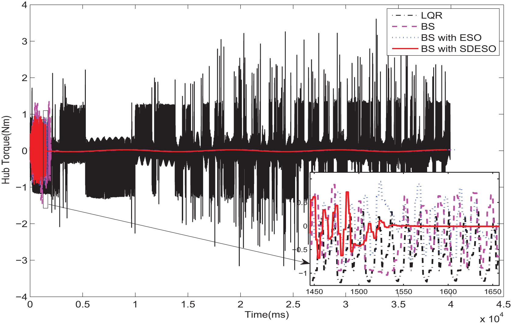
Simulation results for torque profiles of hub-1.
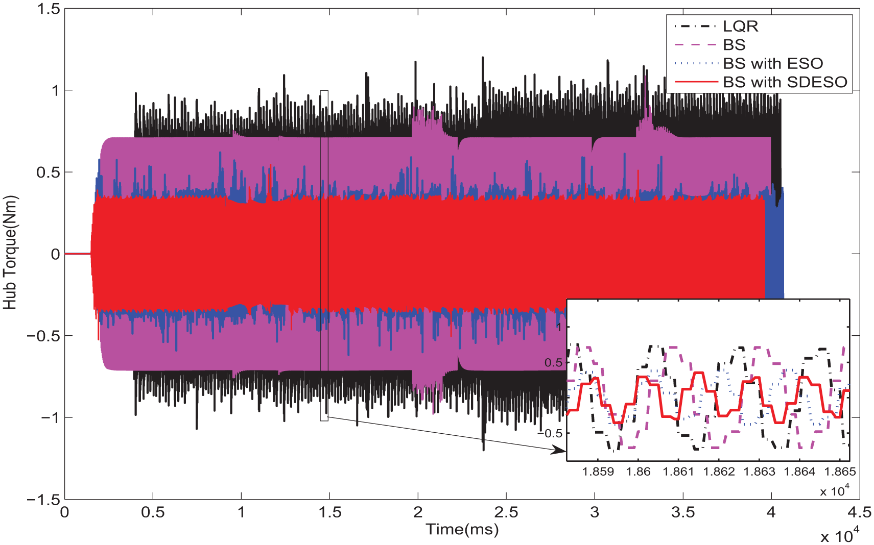
Simulation results for torque profiles of hub-2.
Experimental results
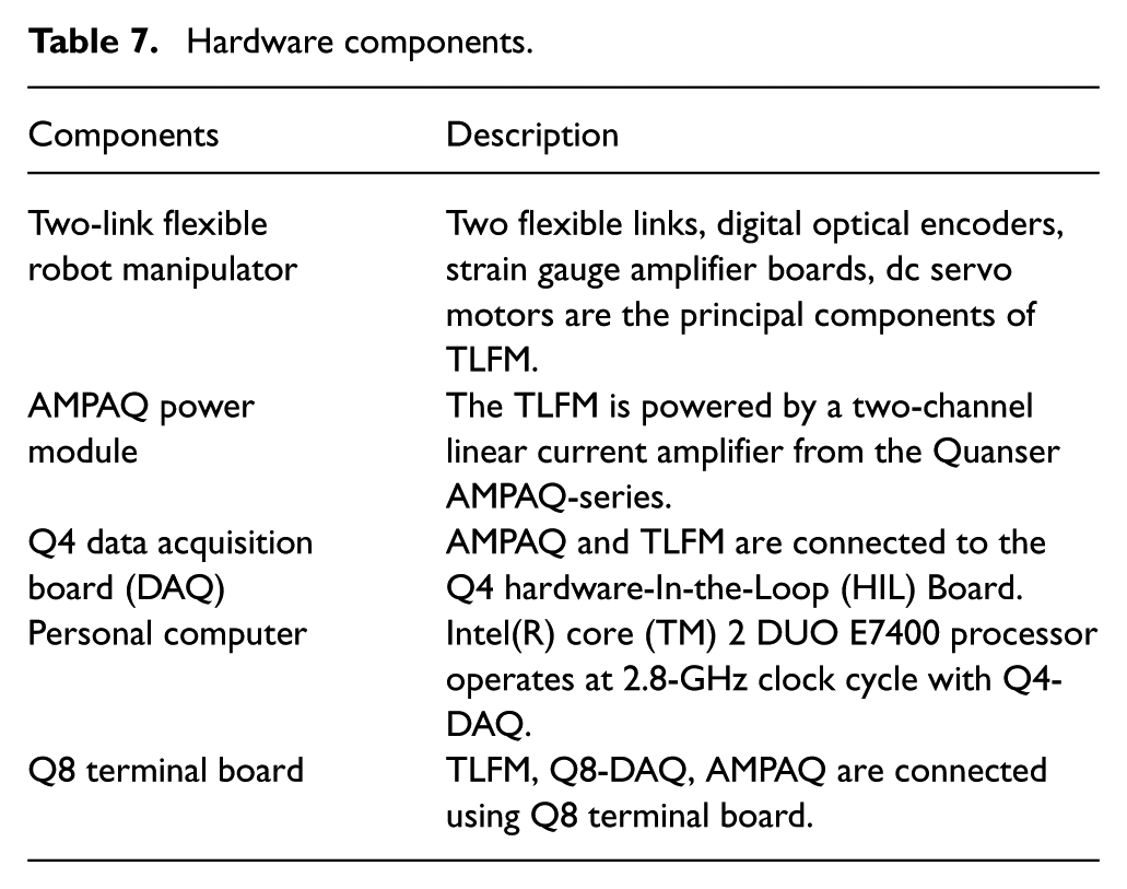
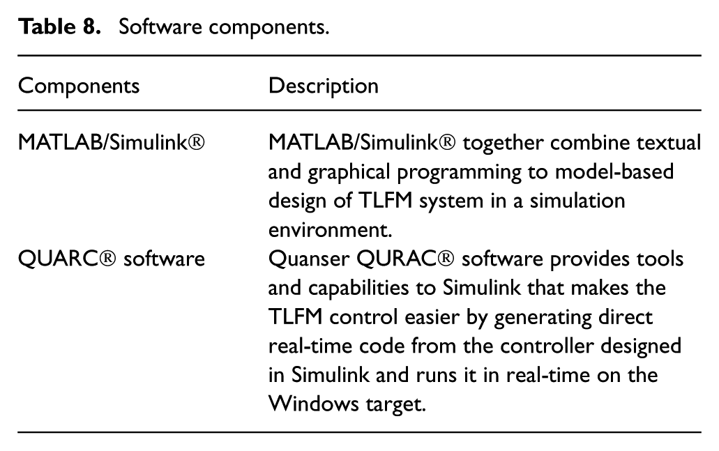
The experimental study was pursued to verify the performance of proposed SD-ESO-based backstepping control of TLFM. The proposed control scheme has been applied to the TLFM available in the Control and Robotics Laboratory, National Institute of Technology, Rourkela. The photograph of the experimental setup is shown in Figure 12. The hardware and software components for the experiment setup are listed in Table 7 and Table 8, respectively. Figure 13 shows the signal flow diagram of the TLFM setup.
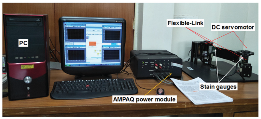
Experimental setup of TLFM.
Hardware components.
Software components.
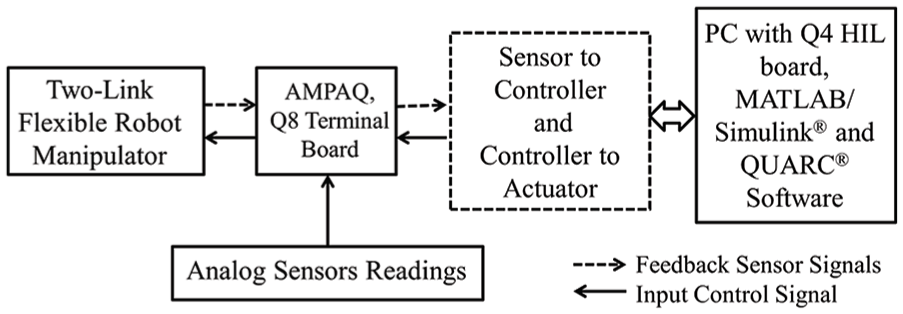
Interfacing of signals for the TLFM.
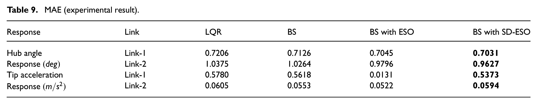
Experimental results of tip-tracking performance of link-1 and link-2 are shown in Figure 14 and Figure 15, respectively. Tip-tracking error profiles of both the links are shown in Figure 16 and Figure 17. The MAE and MSE obtained from experimental studies are listed in Table 9 and Table 10, from which it is observed that both the errors for BS with SD-ESO are lower than that obtained for BS with ESO.
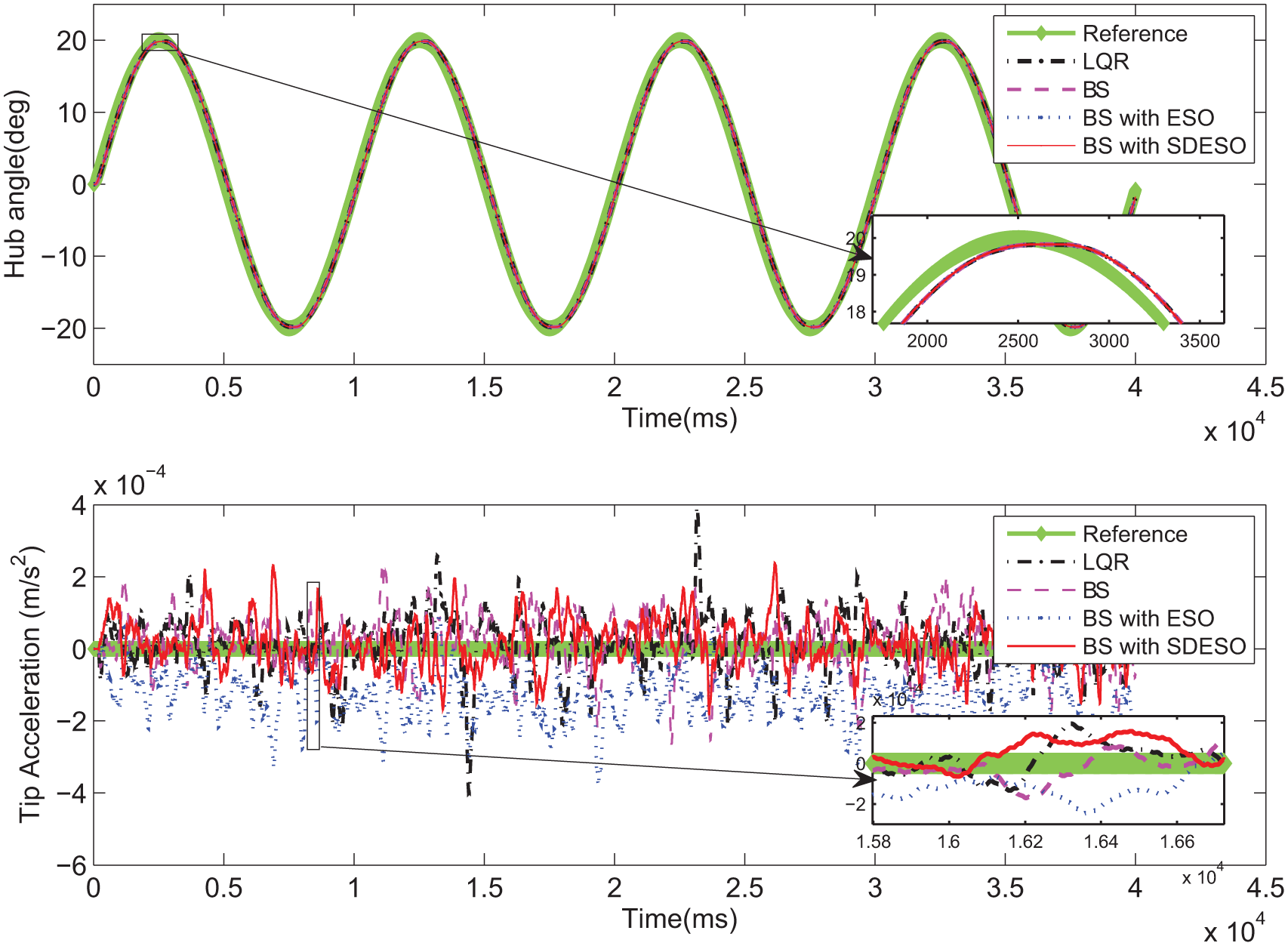
Experimental results for tip-tracking performance of link-1.
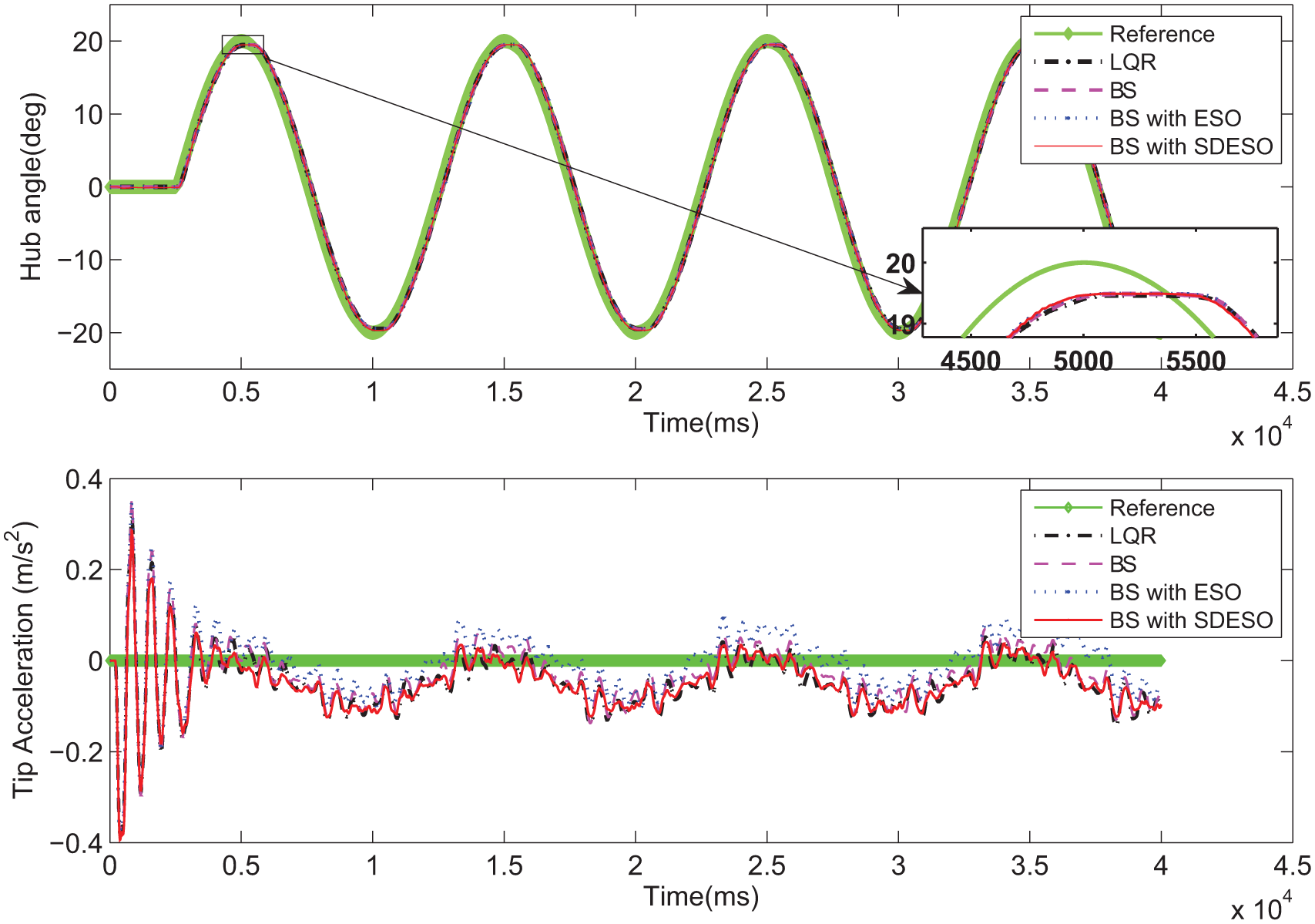
Experimental results for tip-tracking performance of link-2.

Tip-tracking (estimation) error of link-1.
Tip-tracking (estimation) error of link-2.
MAE (experimental result).
MSE (experimental result).
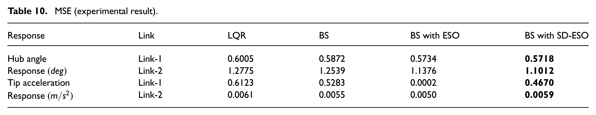
Figure 16 shows the tip-tracking error profiles obtained from experimental results for link-1, which shows that deflection error is 1.086° for LQR, 1.076° for BS controller, 1.07° for BS with ESO, whereas it is 1.055° in the case of the BS with SD-ESO. The tip acceleration error of link-1 is 0.0004
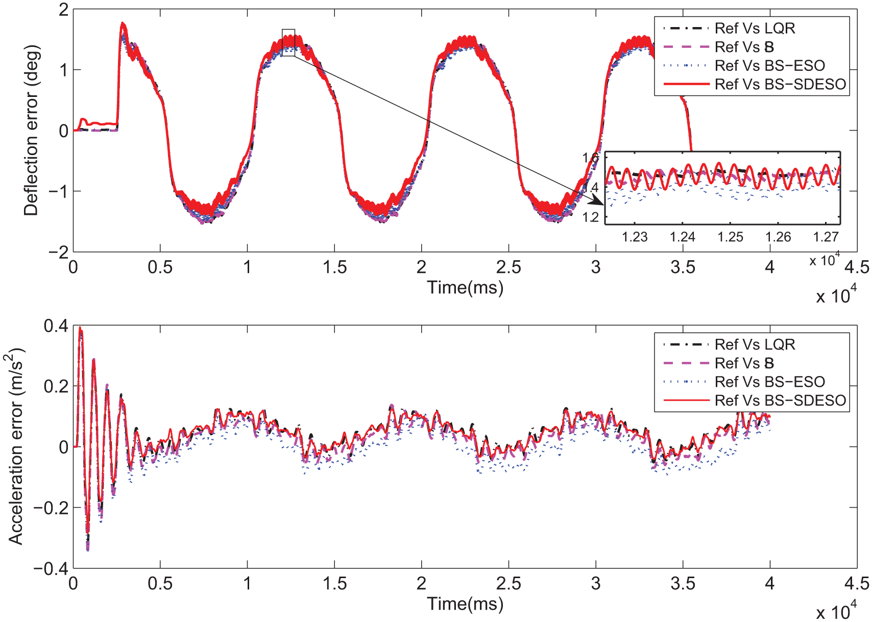
Figure 17 shows the tip-tracking error profiles obtained from experimental results for link-2, which show that deflection error is 1.78° for LQR, 1.6° for BS controller, 1.59° for BS with ESO, whereas it is 1.51° in the case of the BS with SD-ESO. The tip acceleration error of link-2 is 0.13
Tip-tracking (estimation) error (experimental result).
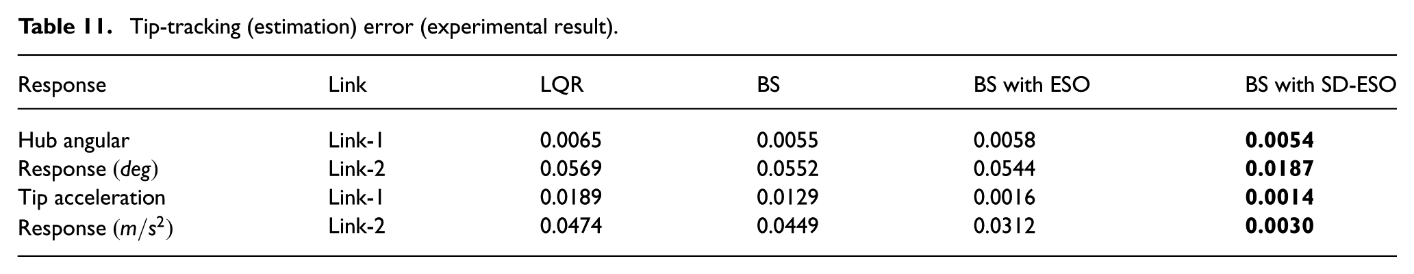
Figure 18 and Figure 19 show the torque profiles generated by LQR, BS, BS with ESO, and BS with SD-ESO for hub 1 and 2, respectively. From Figure 18 and Figure 19, it is observed that the torque generated by BS with SD-ESO is smooth compared with LQR, BS, and BS with ESO with maximum amplitude of 0.05 Nm and 0.015 Nm, respectively. It is observed from the tip-tracking error profiles shown in Figure 16 and Figure 17 that the minimum tip deflection and acceleration error are obtained when the BS with SD-ESO is applied. Also, tip position converges to its desired trajectory with minimum MAE and MSE, with an improved transient response.
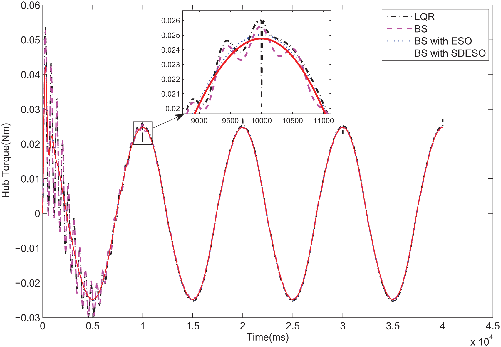
Experimental results for torque profiles of hub-1.
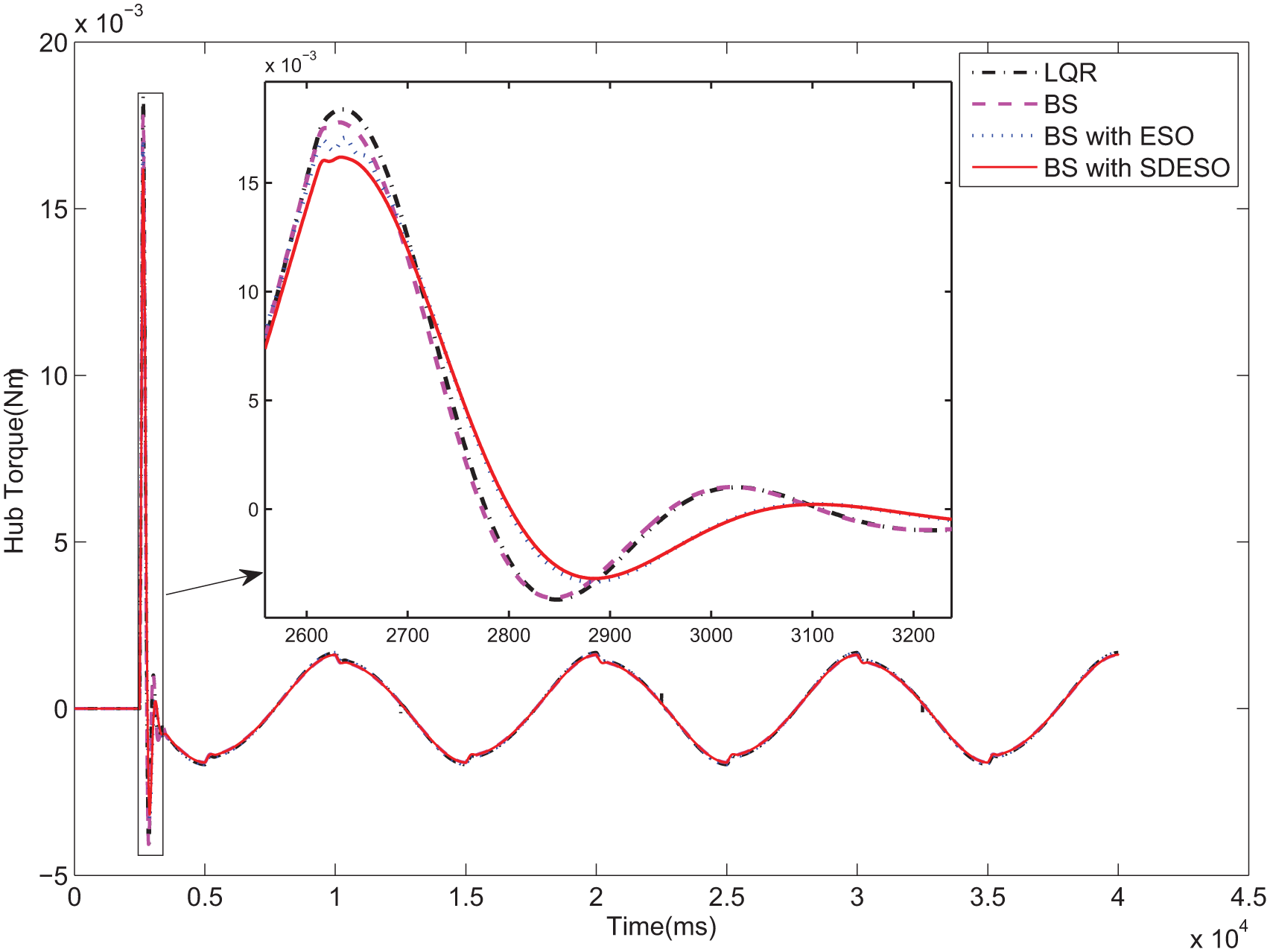
Experimental results for torque profiles of hub-2.
Conclusions
We proposed a new tip-tracking control scheme called sampled-data extended state observer-based BS controller for a two-link flexible manipulator to address the problem of uncertainties and disturbances in its dynamics. Tip positioning and link vibration are two of the most important issues that arise in TLFM due to non-minimum phase behavior together with model uncertainties and external disturbance. We design a SD-ESO to estimate the above uncertainties and disturbance. We then designed a BS controller to accomplish tip-tracking of a TLFM in face of the parameter uncertainty and disturbance. Simulation and experimental results demonstrate the effectiveness of the proposed SD-ESO-based backstepping control scheme. The proposed SD-ESO-based BS controller exhibits excellent tip-tracking performance of the TLFM with input constraint and external disturbance.
Footnotes
Appendix
Declaration of conflicting interests
The author(s) declared no potential conflict of interests with respect to the research, authorship and/or publication of this article.
Funding
The author(s) received no financial support for the research, authorship, and/or publication of this article.