
Abstract
During axial thrusting of a symmetric spinning spacecraft, misalignment and center-of-mass offset can cause unwanted body-fixed torques. The two-burn scheme is applied to eliminate velocity pointing error. Solutions for angular velocity, Euler angle, and inertial velocity with nonzero initial conditions are derived in a new form for axisymmetric spacecraft with constant mass. Simulations show that the solutions closely match numerical simulations and the two-burn scheme decrease the velocity pointing error obviously. Based on the solutions, the effect of two-burn scheme is analyzed. The results show that the spacecraft will obtain the minimum velocity pointing error if the burn and coast times are controlled accurately. Also, the two-burn scheme allows for a lower spin rate and the spacecraft can be maneuvered at nonzero initial conditions compared with the continuous thrust scheme.
Keywords
Introduction
During the burning of a spacecraft motor, thrust vector misalignment from the center of mass always exists and is inevitable (Faber et al., 2013; Kabganian et al., 2018; Zondervan et al., 2014). This misalignment produces a disturbance torque that results in attitude instability and also thrust vector deviation from the desired inertial direction (Ayoubi, 2007; Kong et al., 2016; Martin and Longuski, 2014, 2015). Spin stabilized control is a simple structural method for use in orbital maneuvers of spacecraft (Kong et al., 2016; Morozov et al., 2016; Yang et al., 2017). The criteria in the spinning thrusting problem have been less energy utilization and optimum maneuver execution (McDonald et al., 2014; Safa et al., 2018). In this regard, with a higher spin rate, more energy is used for increasing the spin rate and controlling the spin axis; conversely, with a lower spin rate, the satellite attitude will be more affected by transverse torques arising from the misaligned thrust (Hu et al., 2017; Javorsek et al., 2003; Longuski et al., 2005; Slavinskis et al., 2014). It has been shown that if the axial thrust begins at zero and ramps up to its maximum thrust, angular momentum pointing errors could be significantly decreased (Ayoubi, 2012, 2014; Javorsek and Longuski, 2000; Martin, 2015; Martin and Longuski, 2014). Another method to reduce the velocity pointing error is to use a two-burn scheme in which the burn is momentarily suspended and then restarted to minimize the deviation (Beck and Longuski, 1997; Longuski et al., 1989; Oldenburg and Longuski, 2002).
Solutions for linearized model give insight into the behavior of the motion by providing explicit expressions for periodic motion, secular effects, and asymptotic limits (Ayoubi and Longuski, 2007, 2009; Tsiotras and Longuski, 1996). Although Javorsek and Longuski discuss some analytical results, they did not derive the expressions for the linearized model (Javorsek and Longuski, 2003). Ayoubi and Martin simplified the solutions in the original inertial frame with zero Euler angles. During the second and third thrusting phases, the inertial velocity solutions can be obtained by using a rotation matrix (Ayoubi et al., 2012, 2014; Martin and Longuski, 2014). This paper complements previous works in finding new form solutions for linearized model that can be used on the analysis of two-burn scheme maneuver. Numerical integration of (and comparison with) the original exact differential equations reveals that the solutions are highly accurate and eminently applicable to spin-stabilized spacecraft. Mechanism analyses verified that two-burn scheme can be used to reduce the velocity pointing error during a spinning thrusting maneuver.
Solution for linearized model
Consider a spinning thrusting spacecraft with constant mass properties as depicted in Figure 1. The spacecraft has undesired transverse torques of Mx and My, no axial torque (Mz = 0). Assume the body-fixed reference frame, B, has its origin located at the center of mass and aligned with the principal axes of the spacecraft. Capital letters signify the vector in the inertial reference frames I, and lower case letters signify vectors in the body-fixed frame. By assuming a nearly symmetric spacecraft with no axial torque, the spin rate will be constant.
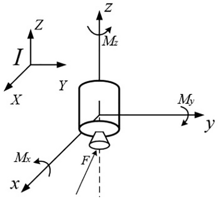
Model for spinning thrusting satellite.
The two-burn scheme is shown in Figure 2 in the inertial reference frame. At the beginning of the maneuver, all the initial conditions for angular velocity, Euler angle, and velocity except for spin rate are set to zero. During the first phase, the angular momentum vector,

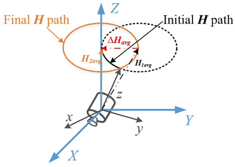
Angular momentum vector during the two-burn scheme maneuver.
Consider a satellite with mass and moment of inertia at a large order of magnitude contrast with the motor, the jet-damping moment and mass variation can be neglected (Janssens and van der Ha, 2014, 2015; van der Ha JC, 1985, 2015). Euler’s equations which governs the rotational motion of the spinning spacecraft during the two-burn scheme maneuver can be written as (Thomson, 1989)
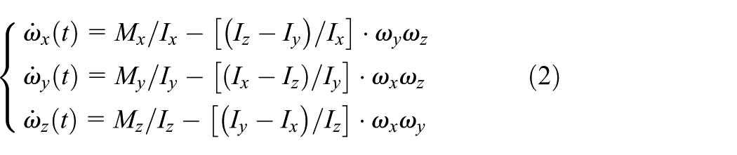
where
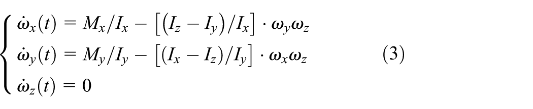
Make ωx(0) = ωx0 and ωy(0) = ωy0, by integrating equation (3), the solutions for transverse angular velocities are as follows
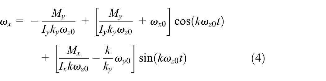
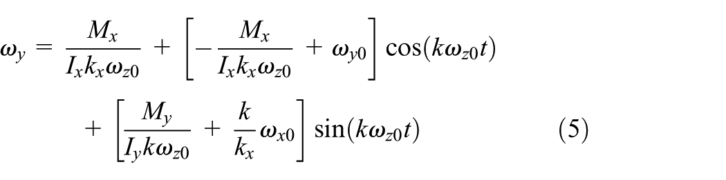
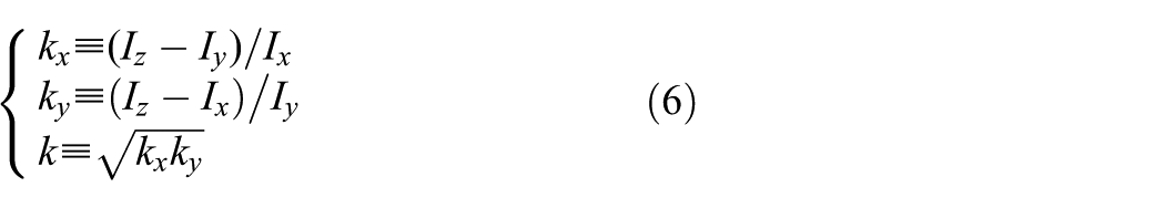
where the parameters kx, ky, and kz are defined as
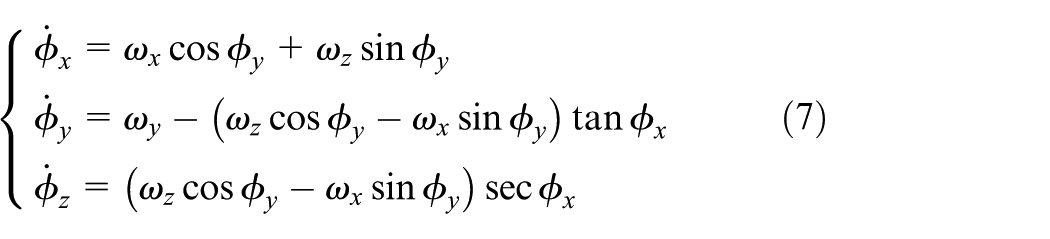
By using a Euler 3-1-2 sequence, the orientation of spacecraft with respect to the inertial reference frame can be described by the following equation (Roldugin and Testani, 2014)
where
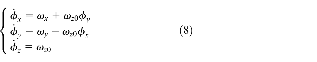
Integrate equation (8) by substituting the angular velocities found in equations (4–5), the solutions for the Euler angles are
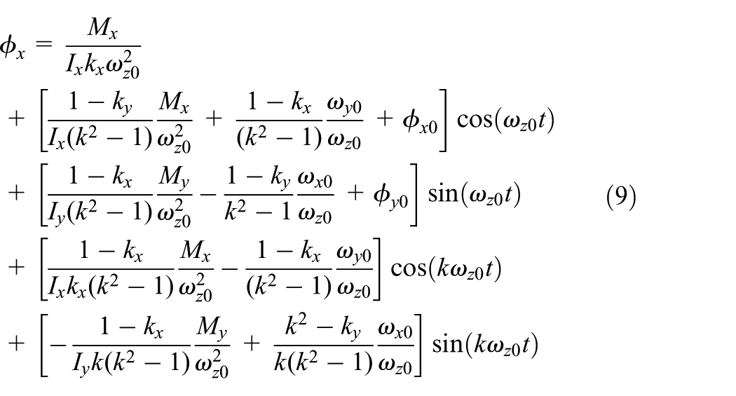
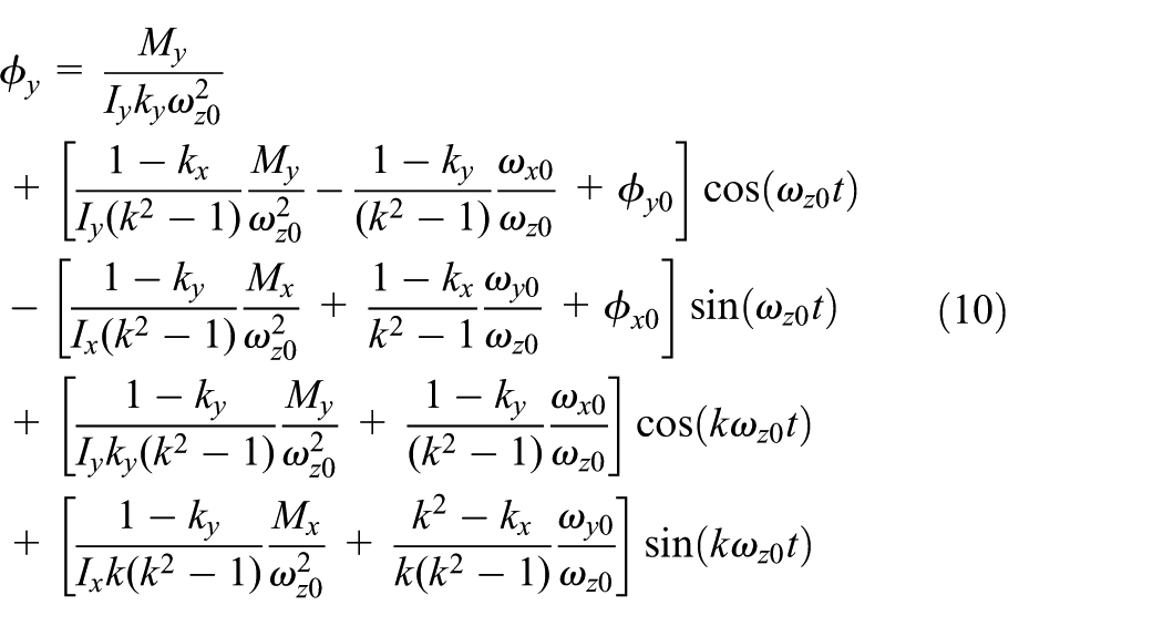

It can be found from equation (9) and equation (10) that the solutions for the transverse Euler angles are in terms of trigonometric functions. The trigonometric functions remain bounded as functions of time so that the nutation will remain bounded. With the presence of constant body-fixed forces (fx, fy, fz) during thrusting (due to thruster imbalance and misalignment, and center-of-mass offset) in the first or third phase, the inertial velocity solution
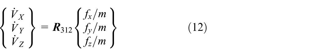
The direction cosine matrix corresponding to a 3-1-2 Euler angle sequence is given by
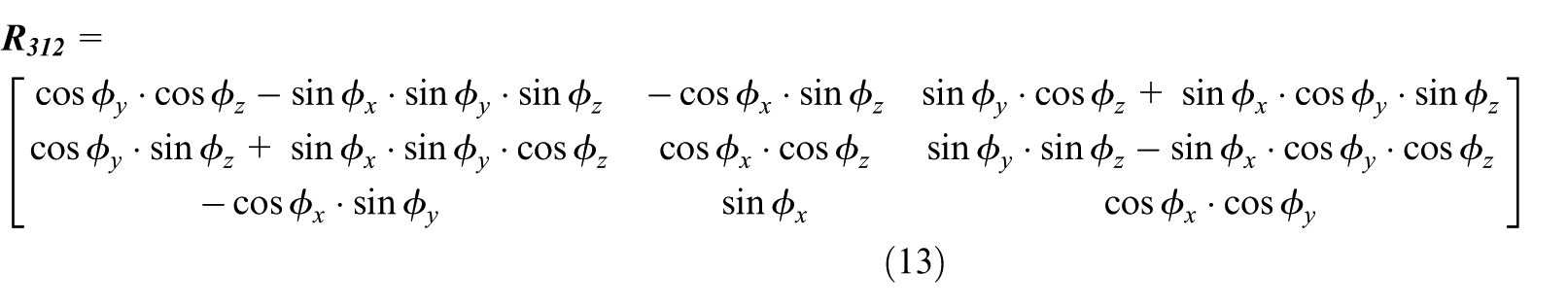
When ϕx and ϕy are small, the direction cosine matrix
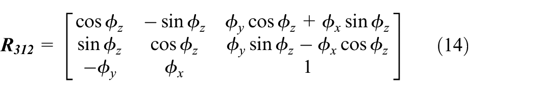
Considering the initial conditions of angular velocities and Euler angles, then substituting equations (4), (5), (9), (10) and (11), respectively, into equation (14) provides
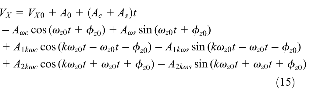
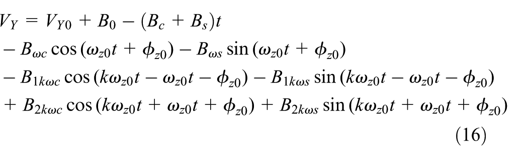
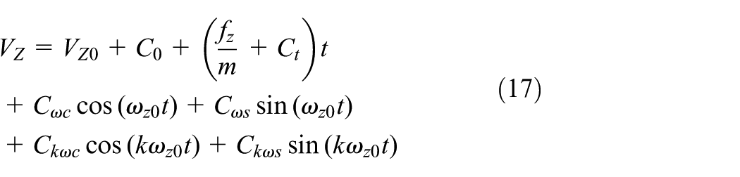
where A, B, and C coefficients are functions of the moments of inertia, initial values of angular velocities and Euler angles, and the coefficients from the torques and forces. The A, B and C coefficients can be found in the Appendix. It can be found from equation (15) and equation (16) that the transverse velocities are growing linearly during the whole two-burn scheme maneuver. Because the axis velocity Vz is governed by the secular effects as the transverse disturbances are negligible in comparison to the axis force (Martin, 2015), the axis velocity Vz can be reduced to
Simulation and numerical results
MATLAB are used to verify the solutions for linearized model. The simulation uses a built in MATLAB integrator, ode45, an explicit Runge-Kutta formula, to solve for the differential equations numerically. The variable step size integral uses tight relative and absolute error tolerances (on the order of 10−16) and normal control.
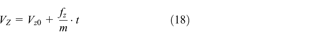
To test the accuracy of solutions, the example is based on a spacecraft with the following mass properties, initial conditions, and spin rates in Table 1 (Longuski, 1991). Unlike the solutions presented before, the higher fidelity model including linearly changing principal moments of inertia for all three axes to provide a model that is as accurate as possible. The model also assumes a constant mass-flow rate. And to demonstrate the potential effectiveness of two-burn scheme maneuver, the same simulation was run with a continuous thrust scheme.
Spacecraft parameters.
For the present purpose, a fictitious thrust profile is used. In the first phase, all the initial conditions except for ωz0 are set to zero, but at the end of the first phase, these values are nonzero. During the second phase, the thruster turns off, the conditions at the end of the first phase become the initial conditions of the second phase. Without any external torques, the angular momentum vector becomes stationary in the inertial space, but the spacecraft continues to spin, the transverse angular velocities and Euler angles are changing continuously. Because the thrust is zero in the second phase, the velocities in the inertial space will be constant and nonzero. After the coast time, the thruster turns on again, and the initial conditions for transverse angular velocities, Euler angles, velocities are equal to the final conditions of the second phase.
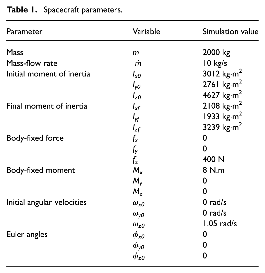
Figure 3 shows the magnitude of transverse angular velocity, ωx, for numerical integration and solution computation. The result for ωy is similar, and so we do not present its plot. The transverse angular velocity dramatically changes at 0.997 s and 1.994 s when the second phase and third phase begins. During a normal spinning thrusting maneuver subject to constant forces, ωx oscillate around an average value of 0 rad/s with an amplitude of 0.004 rad/s. But during a two-burn scheme maneuver, ωx oscillate around 0 rad/s with an amplitude of only about 0.0025 rad/s. An additional benefit from the two-burn scheme is that the amplitude of the transverse angular velocities decreases.
Numerical integration and solution computation for angular velocity ωx.
From Figure 3, we note that the numerical integration and solution computation are indistinguishable during the maneuver process for the transverse angular velocities. To display the error in the solution computation, we plot the difference between the numerical integration and solution computation in Figure 4. According to the expression (2), the spin rate will increase as the principal moment of inertia about z-axis decreasing. Thus, the variation period of ωx decreases as the burn time increasing. Here, we found that the error grows obviously at the end of the two-burn scheme. But the error is of the order 10 −4 rad/s after 60 s, which proves the high precision of solutions.
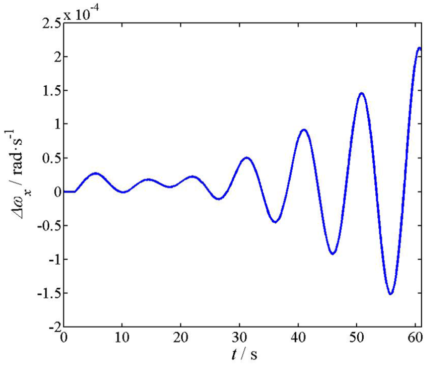
Numerical integration minus solution computation for transverse angular velocity ωx.
Figure 5 shows the magnitude of Euler angle, ϕx, for numerical integration and solution computation. During a spinning thrusting maneuver subject to constant forces, ϕx oscillate with an amplitude of 0.004 rad. It can be found from Figure 5 that the ϕx oscillate with an amplitude decreases from 0.004 rad to 0.0017 rad under a two-burn scheme maneuver. Because the thruster misalignment is assumed in the body-fixed y-z plane, the only torque the thruster produces is Mx. With the principal moments of initial changing linearly, the error of ϕx become obvious at the end of maneuver.
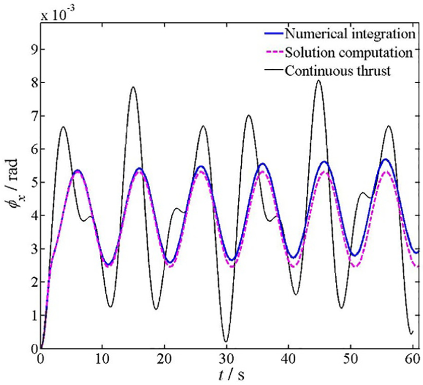
Numerical integration and solution computation for Euler angles ϕx.
We plot the error of ϕx between the numerical integration and solution computation in Figure 6. Here, we see that, although the difference grows with time, the error is of the order 10−4 rad after the maneuver.
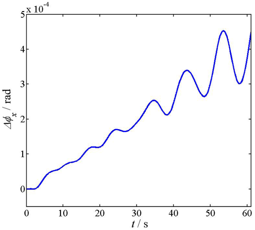
Numerical integration minus solution computation for Euler angle ϕx.
The numerical integration and solution computation for inertial velocity, VX, is plotted in Figure 7. As the thruster has a small center-of-mass offset along the x-axis, VX is bounded (we do not present its plot) and VY grows linearly with time during the continuous thrust scheme. But during a two-burn scheme, both VX and VY are bounded. As the total impulse is held constant, the final axis velocity is nearly identical at about 12m/s in both the continuous thrust and two-burn maneuver. The errors in the solution computation caused by compounding errors from the angular velocities and Euler angles are relatively small.
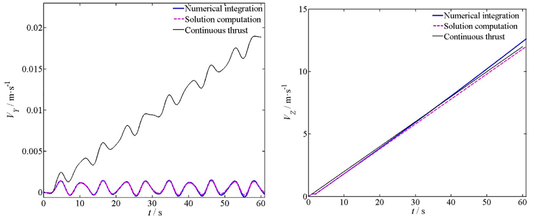
Numerical integration and solution computation for inertial velocities VY and VZ.
Figure 8 present the errors of VX and VZ between two results. We see that the error grows to order 10−4 m/s for VX and to 0.1 m/s for the axial component after the two-burn scheme maneuver.
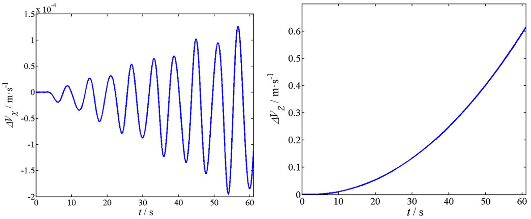
Numerical integration minus solution computation for inertial velocities VY and VZ.
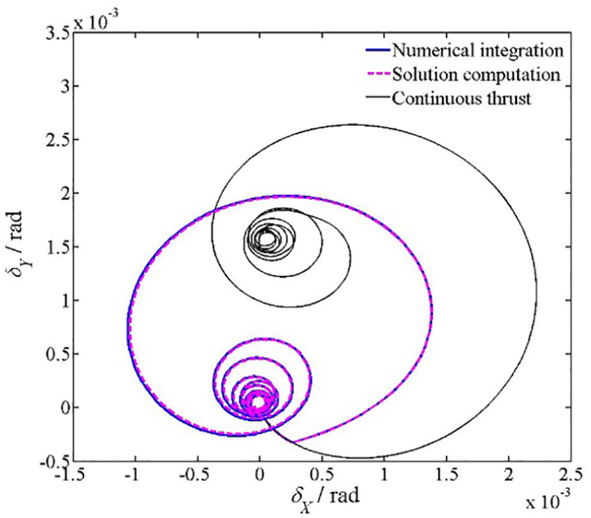
The velocity pointing error is defined as (Olson et al., 2014)
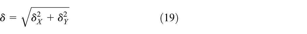
where δX and δY are the velocity pointing angles defined as

Because the velocity pointing error is small, the velocity pointing angles can be simplified to

In Figure 9, we show the numerical integration and solution computation for the pointing error components of the inertial velocity vector, the difference is indistinguishable. It can be found that the pointing error begins at the origin and winds around a point located at approximately 0.12 mrad. With a continuous thrust scheme, the average velocity pointing error is about 1.6 mrad, which is more than 13 times larger than the average pointing error of the two-burn scheme maneuver.
Velocity pointing error for continuous thrust and two-burn scheme.
Assuming a symmetric or near symmetric rigid body IxIy under the influence of a single torque Mx, the spin rate is constant with time. It can be found from Figure 3 to Figure 9 that angular velocity, Euler angle, velocity and velocity pointing error are relatively insensitive to variations in principal moments of inertia for all three axes if the orientation changes in
According to Figure 9, the velocity pointing error for two-burn scheme maneuver is determined by running the simulation until it converged on a point. But due to the stochastic errors in the real system, it is expected that the velocity pointing error, δ, could end at any point on a small circle as represented in Figure 10. During the stability analyses simulation process, the velocity pointing error is defined as the center of the circle as shown in Figure 10. The radius and center are determined by fitting the last 2% of the data to a circle.
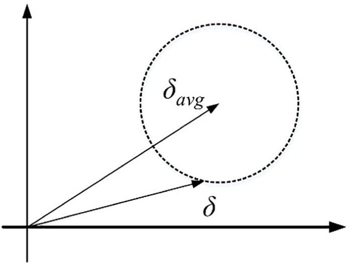
Definition of velocity pointing error δavg.
It has been shown that if the burn and coast times, tb and tc, are controlled precisely during the two-burn scheme, the velocity pointing error could be significantly decreased with respect to the continuous thrust case. But as the thruster cannot be shut off and turned on in time exactly, the actual velocity pointing error is unclear during the two-burn scheme maneuver. To determine the influences produced by the errors of burn and coast time, tb and tc are varied to get the velocity pointing error. Figure 11 shows the two-burn scheme maneuver velocity pointing error when tb and tc are varied.
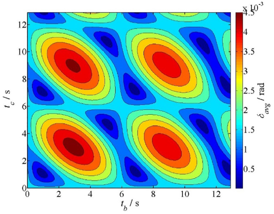
Velocity pointing error varying tb and tc.
In Figure 11, the burn and coast times, tb and tc, varying from zero to 12.96 s with a total burn time of 60 s. The velocity pointing error in the blue shaded areas locate the minimum value, which appear the region of tb or tc waiting additional revolutions exactly. Thus, the full range of possible burn and coast times is
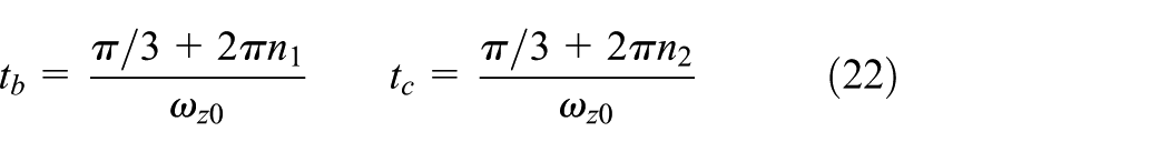
Also, the velocity pointing error in the red shaded possess the maximum value. It can be found that when tb = tc = (2n+1)π/ωz0, the velocity pointing error reaches a maximum value, which is even higher than the continuous thrust process. Figure 12 shows the angular momentum vector in the inertial XY plane of the thrusting process that the spacecraft reaches the maximum velocity pointing error. The offset of the final angular momentum vector path is twice more than the initial path.
Angular momentum vector during the maximum velocity pointing error process.
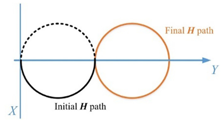
Taking an entirely different perspective, if the velocity pointing error of the constant burn (at 1.6 mrad) is acceptable, the spacecraft could spin at a lower rate while using the two-burn scheme. Figure 13 shows the variable ωz0 for two-burn scheme maneuver with a transverse torque of 8 N.m. We see that with a two-burn scheme, the minimum spin rate to achieve a 1.6 mrad velocity is 0.47 rad/s, which is around 45% of the original spin rate.
Velocity pointing error varying ωz0.
The primary weakness of the original two-burn scheme mentioned in the preceding paragraph is the zero initial conditions assumption. As the spin-up attitude control phase cannot be finished ideally, the initial spacecraft attitude is unclear during a spinning thrusting maneuver (Zhang, 2018). To determine the influences produced by the initial attitude, initial transverse velocity and Euler angle are varied to get the velocity pointing error. Figure 14 shows the angular momentum vector in the inertial XY plane with nonzero transverse angular velocity and Euler angle during a continuous thrust scheme (represented by a black line). We can find that if the burn and coast times, tb and tc, are controlled using equation (22), the angular momentum vector pointing error (represented by a green dashed line) has a little change contrast with the continuous thrust case. Here, we present a general way (represented by an orange line), which can be regarded as the optimal method produce the minimum angular momentum vector pointing error during a two-burn scheme maneuver. The center of the general two-burn scheme
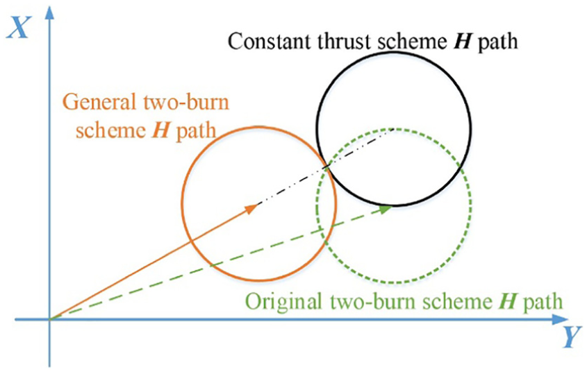
Angular momentum vector for three maneuver types.
Figure 15 shows how initial transverse angular velocities change the velocity pointing error. The spin rate, ωz0, is constant with the initial transverse velocities varying from -0.1 to 0.1 rad/s. It can be found that the maximum velocity pointing error for this search space is about 30 mrad for both ωx0 and ωy0 up to 0.1 rad/s.
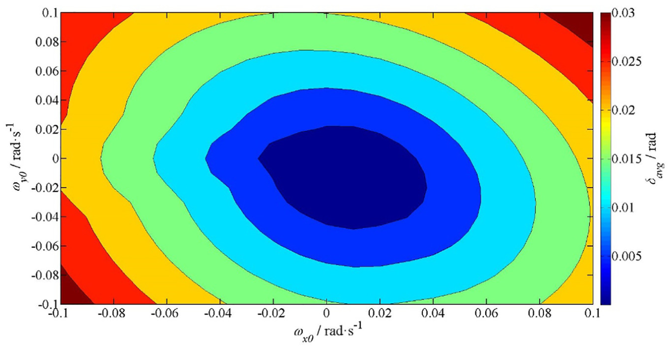
Velocity pointing error varying ωx0 and ωy0.
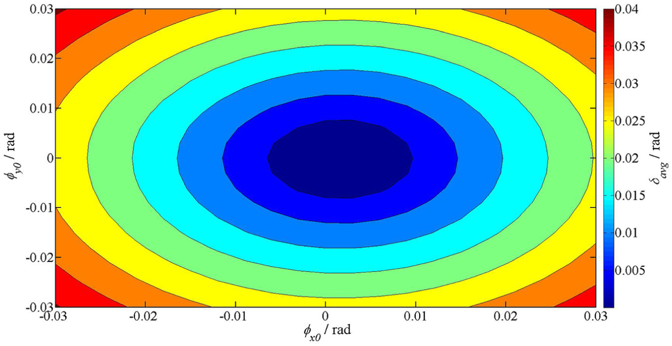
Figure 16 shows how initial Euler angles change the velocity pointing error. The initial Euler angles varying from -0.05 to 0.05 rad. The maximum velocity pointing error for this search space is more than 40 mrad with ϕx0 and ϕy0 of around 0.03 rad. It seems that the initial Euler angles variation produce larger velocity pointing error than angular velocities variation during a two-burn scheme.
Velocity pointing error varying ϕx0 and ϕy0.
In Figure 15 and Figure 16, as the initial transverse angular velocities and Euler angles increases, the velocity pointing error increases. If the velocity pointing error of the continuous thrust scheme (at 1.6 mrad) is acceptable for a zero initial attitude conditions, a spacecraft with a two-burn scheme could be maneuvered at a nonzero initial transverse angular velocity under 0.06 rad/s or an initial Euler angle under 0.03 rad.
Conclusion
Spin-stabilized spacecraft is typically affected by center of mass offsets and misalignments of the thrusting thruster, causing the intended velocity to have undesired deviation. The two-burn scheme presented here can be used to reduce the velocity pointing error greatly in axially thrusting spacecraft spinning at a constant rate. Solutions for linearized model are redeveloped for the two-burn scheme, and provides highly accurate for the angular velocity, Euler angle and inertial velocity. Simulations are provided for a fictitious two-burn scheme, the numerical tests not only confirmed the accuracy of the solutions but also indicate that the linearized model are relatively insensitive to the variations of spacecraft mass. The results also reconfirmed that the two-burn scheme can be used to reach an order of magnitude improvement over a continuous thrust process.
Based on the solutions, burn and coast times were varied to get the velocity pointing error during the two-burn maneuver. The spacecraft will obtain the minimum velocity pointing error when the burn and coast times are waiting additional revolutions exactly. Thus, it is very important to control the burn and coast times precisely during the two-burn scheme.
The spin rates, initial transverse velocities and Euler angles are varied to get the velocity pointing error. If the velocity pointing error for the continuous thrust profile with zero attitude conditions is acceptable, the two-burn thrust scheme allows for a lower spin rate and the spacecraft could also be maneuvered at a nonzero initial transverse angular velocities under 0.06 rad/s or an initial Euler angle under 0.03 rad.
The two-burn scheme maneuver may be used to increase accuracy and to decrease fuel expenditure for orbital injection and large orbit correction maneuvers.
Footnotes
Appendix
The coefficients for the inertial velocity solutions are listed in the following sections. For clarity, the X axis coefficients begin with A, the Y axis coefficients begin with B, and the Z axis coefficients begin with C.
Declaration of conflicting interests
The author(s) declared no potential conflict of interests with respect to the research, authorship and/or publication of this article.
Funding
This work was supported by the National Natural Science Foundation of China Project (Grant Nos. 61803204) and the Six Talent Peaks Project of Jiangsu Province of China (Grant Nos. TD-KTHY-001).