The integration of renewable energy resources to DC microgrid has captured the attention of the researchers in recent years. One of the active field of application of DC distribution is the islanded DC microgrid (DC ImG). The DC ImG present numerous challenges to researchers. Among many challenges, the regulation of voltage and stability of the system is indispensable to efficient operation. The voltage stability problem becomes more prominent when the system is exposed to disturbances and possess uncertainties in parameters. However, challenges can be overcome by skilful design of a robust controller for the system. Therefore, in this paper, an output-feedback based centralized robust control scheme is proposed. The proposed controller is designed to maintain good control performance in the presence of parametric uncertainties and exogenous disturbances. The uncertainties of the DC microgrid is modelled as a linear time-varying state-space system. The upper and the lower bounds of the time-varying parameters are determined by a Lebesque-measurable matrix. To attenuate the exogenous disturbances of the system based output-feedback controller is designed. The system stability is assured by the Lyapunov function candidate. The output-feedback controller needs only the voltage measurement; therefore, it requires less communication bandwidth as compared to the state-feedback. To obtain the controller parameters linear matrix inequality constraints are formulated and solved. The performance of the proposed controller is verified via simulations and compared with the existing schemes.
In recent years, the penetration of distributed generation units (DGUs) has increased. Most of these DGUs generate electrical energy using renewable energy sources (RES) and provide outputs as DC power. Therefore, integrating them with a DC system is a natural choice. The integration of these RES with DC distribution systems would provide several benefits (Elsayed et al., 2015; Mohamed et al., 2017; Papadimitriou et al., 2015). The DC power distribution systems has many advantages compared to its AC counterpart. For example, DC systems eliminate inherent problems associated with AC systems such as synchronization, harmonics, and active-reactive power flow controls (De Doncker, 2014). The basic pros of DC systems include increased system efficiency owing to less conversion losses from sources to loads, no control of frequency, reactive power, and higher power quality. Moreover, the use of DC systems can reduce the required right-of-way and weight of a power network by 10 tons/MW compared with the use of AC systems (De Doncker, 2014). The DC microgrid (DCMG) systems are also gaining attention in broader applications such as electric aircrafts, electric vehicles, aerial vehicles, aircrafts, spacecrafts, naval ships, watercrafts, submarines, and information/telecommunication systems (AbdElhafez and Forsyth, 2009; Becker and Sonnenberg, 2011; Kim et al., 2018; Oulis Rousis et al., 2018). Most of these applications operate as DC islanded microgrids (DC ImGs), which is an active field of research these days. DC ImGs present numerous challenges to researchers in each of the above applications.
From the perspective of communication, control of the DCMG can be categorized into four general schemes, which are as follows:
Centralized control: The data from DGUs are collected in a centralized station, and feedback control signals are sent back via dedicated communication links (DCLs) (Dragicevic et al., 2014).
The advantages of centralized control systems are simple implementation and strong observability and controllability. As the status of all DGUs are collected and processed at a single point, the centralized control provides the basis of employment of advanced control functionalities. However, centralized control also has disadvantages such as a single point of failure, less expandability, and less flexibility. The primary advantage of decentralized control scheme is that a real-time communication system is not required. However, lack of coordination between the DGUs control system limits the possibility of achieving global coordinated behaviors. One of the major advantages of a distributed control system is that it has no single point of failure. Moreover, the system’s observations reduce if DGUs are not connected with each other via a DCL. Hierarchical control is formed by combining both centralize and decentralized schemes and offers higher reliability and complex functionalities.
Several studies on control of DCMGs have been conducted. Recent studies (Sadabadi et al., 2017; Tucci et al., 2016) have modeled load disturbance as a measurable quantity and interconnection of DGUs as a system uncertainty. In Tucci et al. (2016), the load disturbance effect is attenuated by introducing an output compensator that also gives the system asymptotically stability. In Sadabadi et al. (2017), norm-reduction-based feed-forward controller is applied to minimize the load disturbance effect. The uncertainty in the system is considered owing to plug-n-play functionality of DGUs, which is modeled as a polytopic-type uncertainty. The parametric uncertainties of converters have been studied in Liu et al. (2018), Kim and Son (2015, 2017), Khayat et al. (2017), Lee et al. (2016), Chaoui et al. (2016), Yang et al. (2013) and Dou et al. (2013). In Liu et al. (2018), model predictive control methodology is applied to linear parameter-varying buck converter. Kim and Son (2017) uses proportional-integral observers for a DC-DC boost converter in order to maintain the desired voltage in the presence of input voltage variation and parametric uncertainty. Similarly, for the input disturbance rejection and parametric uncertainty, Khayat et al. (2017) models lumped multiplicative uncertainties of a boost converter as the linear fractional transformation of the closed-loop system and achieves robustness. Adaptive control schemes are studied in O’Keeffe et al. (2018), Lee et al. (2016) and Chaoui et al. (2016). A based switching rule for a boost converter is proposed in Yang et al. (2013). For AC-bus disturbance attenuation, a double loop robust control scheme has been designed in Dou et al. (2013), where the controller performance criterion, for a single DC-AC converter, has been treated as a linear matrix inequality (LMI). The LMI with additional constraints has been solved as a control problem.
In previous studies, DC ImGs with fixed parameter DGUs were considered. However, some researchers have studied uncertainties of single DGUs, that is, stand-alone DGUs. The uncertainty of DGUs can affect the stability of DC ImGs. Moreover, the buses in DC ImGs have strong mutual coupling; load or source disturbances at one DGUs can cause variations in other buses. In the majority of previous investigations, researchers have either ignored the coupling term or minimized it and have suggested decentralized control scheme. The control system does not guarantee the stability of DC ImGs if the strong coupling terms are not considered during the controller design phase. Therefore, to have a dynamic and robust control scheme for a DC ImG, it is imperative to consider all disturbances and parametric uncertainties of the DGUs; furthermore, the couplings among the DGUs must be modeled.
In this paper, we propose an output-feedback-based control scheme that maintains strict voltage regulation at the output of DGUs under disturbances and parametric uncertainties. First, an appropriate average model of DC ImG is developed with capturing disturbances, parametric uncertainties, and couplings between DGUs. The line dynamics are asymptotically stable owing to the positivity of the line parameters; therefore, in this step, the quasi-stationary line (QSL) approximation suggested in Tucci et al. (2016) is considered. In the second step, the uncertain parameters of DGUs are expressed as a sum of a time-invariant mean value term and time-varying uncertainty. The time-varying uncertainties are considered to be bounded and satisfy the Lebesque-measurable matrix-valued function subject to conditions given in Liu et al. (2007). From the Lebesque-measurable condition, the upper and the lower bounds of the uncertainties are determined. To guarantee the stability of the DC ImG in the presence of disturbances and uncertainties, the norm technique is used, which is converted into LMIs (Boyd et al., 1994). The LMIs provide the necessary constraints for stability and robustness under parametric uncertainties, which are solved to achieve the control system gains. The designed controller offers strict voltage regulation, reduces disturbances, and exhibits robustness to parametric uncertainties.
Thus, in order to control a DC islanded microgrid in large with uncertainties and disturbances, we will formulate the output-feedback controller in terms of LMIs and solve it. Our goal is to develop a dynamic control scheme that guarantees robustness and stability of the system. In this study, the following are achieved: (1) modeling of the uncertainties of a DC islanded microgrid; (2) determination of the upper and lower bounds of the uncertainties; (3) determination of the LMI constraints for which the system would be robust against exogenous disturbances and uncertainties; and (4) development of a new robust dynamic output-feedback control scheme.
Subsequent sections of the paper are organized as follows. Section 2 provides mathematical modeling of the DC ImG under study by considering QSL approximation. Robust tracking dynamics of the controller is also discussed in Section 2. In Section 3, basic theory of robust control system is discussed. Section 4 formulates a multi-objective MIMO linear-time-varying (LTV) system for the mathematical model achieved in Section 2. In addition Section 4 provides the important assumption about the uncertainty of the system. The design of the proposed control scheme is discussed in Section 5; important theorem and problem formulations are also provided in this section. Results are provided in Section 6. The final section provides concluding remarks.
Standard notations used in this paper are as follows: and 0 stand for identity and zero matrices of appropriate sizes, respectively. The transpose of matrix is represented as . A special sign ⋆ is used to represent transposed off-diagonal elements of symmetric matrices. The expressions and mean positive-definite and negative-definite matrices, respectively. The mathematical theorems or lemmas applied are discussed within the paper.
Mathematical formulation
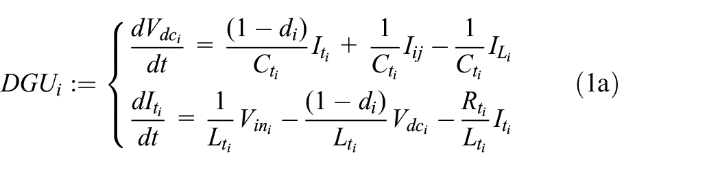
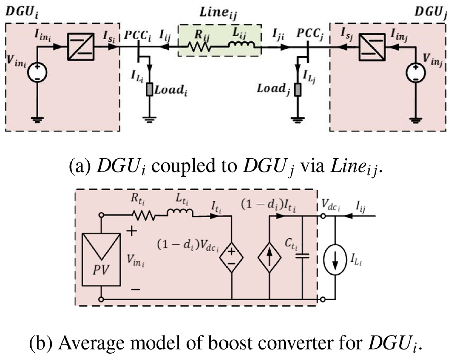
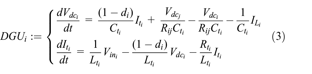
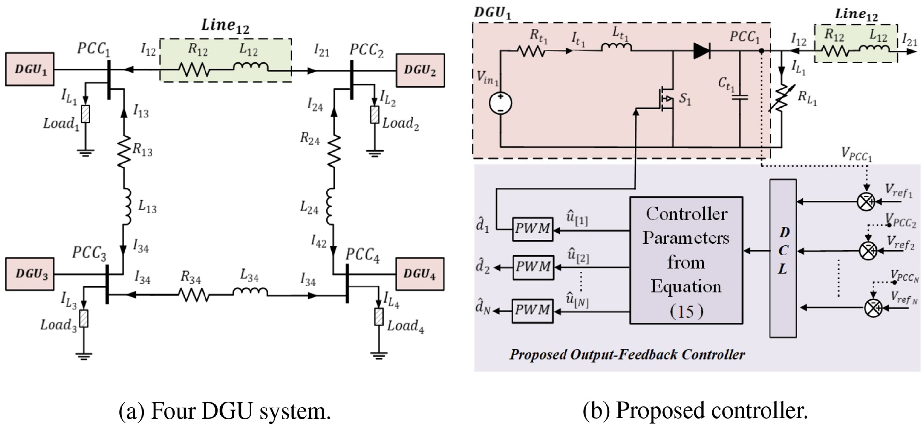
Consider the two coupled DGUs as shown in Figure 1(a). and are coupled through a line . The line parameters are and . The DGUs connected at the point of common coupling (PCC) can be different types of DC–DC converters, such as buck or boost, as per application requirements. In our study, a boost converter with uncertain parameters is considered. The average model of is shown in Figure 1(b), where the input voltage is a generic DC voltage source representing a renewable source; for example, photovoltaic system. The loads are unknown and, thus, modeled as a current disturbance . The signals for are and ; similarly, the signals for are and . From O’Keeffe et al. (2018), the dynamic equations for and can be described as follows
where is the duty cycle of the boost converter. The DGU parameters and are time-varying parameters and have uncertainties. The line currents fulfil . Moreover, the line parameters are , and .
Coupled DGU system.
Quasi-stationary-line (QSL) model
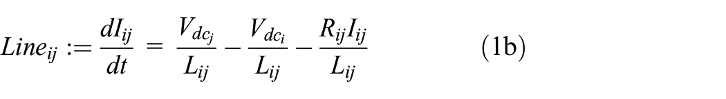
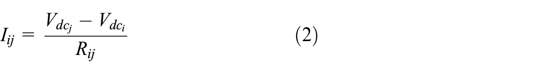
If the time constant of the line transients is very fast, that is, assuming and are significantly small, then the line dynamics can be neglected, that is, . This is known as a quasi-stationary line (QSL) approximation (O’Keeffe et al., 2018; Sadabadi et al., 2017; Tucci et al., 2016). Thus, the line current can be expressed as
Applying (2) to (1a) gives the QSL approximation of , which is expressed below
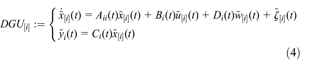
The QSL approximation of the is similar to (3). In the expression (3), the duty-cycle control input is multiplied with the state vector, which makes it a non-linear model. This non-linear dynamical system is linearized around the set . Let be the sum of two terms expressed as , where is a DC quiescent value and represents small superimposed AC variations (Erickson and Maksimovic, 2007). Linearization of (3) around the set gives the small-signal linear time-varying (LTV) model for the , which is represented as below
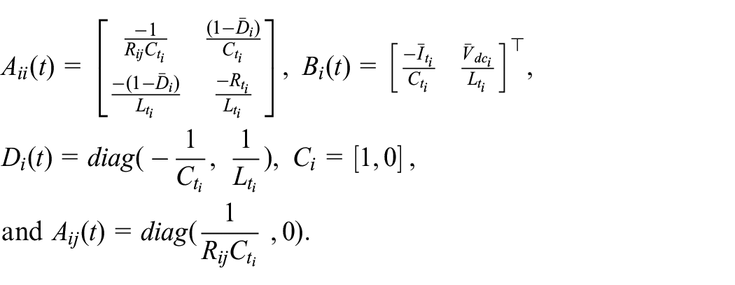
where is a small-signal state vector, is a small-signal pulse width modulation (PWM) control input to , are small-signal exogenous disturbances, is a coupling term between and , is the output vector. The matrices in (4) are as follows
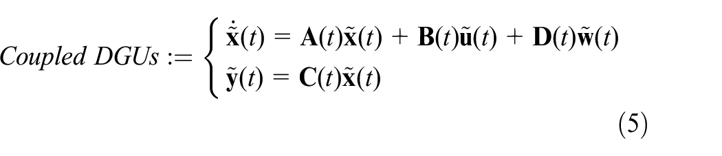
From (4), the small-signal state-space representation of the coupled DGUs in Figure 1(a) can be expressed as
where , , , , , , , and
QSL model for N DGUs
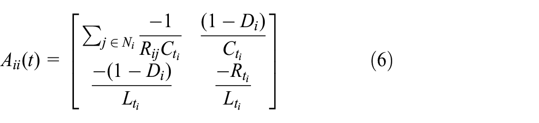
Let be a neighboring subset of , which is coupled via links . For the , the terms and become
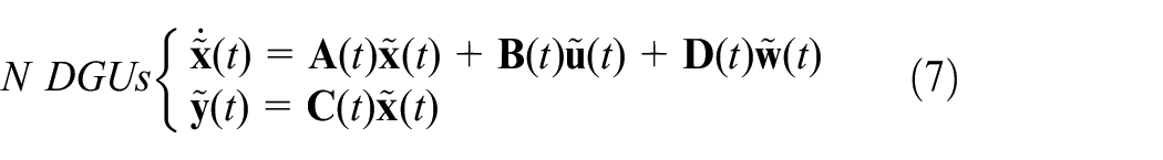
The N DGU small-signal LTV model in the compact form is
where , , , , , , , and
Robust tracking
For the controller of the DC ImG, it is necessary to not only reject the disturbances and uncertainties, but also track a trajectory as closely as possible. Therefore, for voltage tracking, we consider an integrator that would reduce the steady-state error signal. Let the error be the difference between the reference and output voltages, then the small-signal dynamic of the error is represented as
where is the free design parameter in the integrator dynamics. The LTV system in (4) is augmented to accommodate
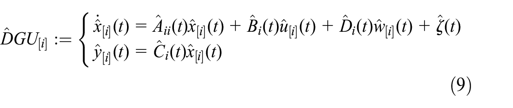
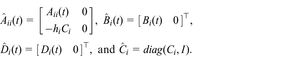
where is a small-signal augmented state vector, is a small-signal PWM control signal to , represents small-signal exogenous disturbances, is the coupling term between the and , and is the output vector. Other matrices of (9) are defined as follows
From (7) and (9), the N DGU augmented state-space equation can be expressed as
where states and matrices are defined according to (7).
Robust control system
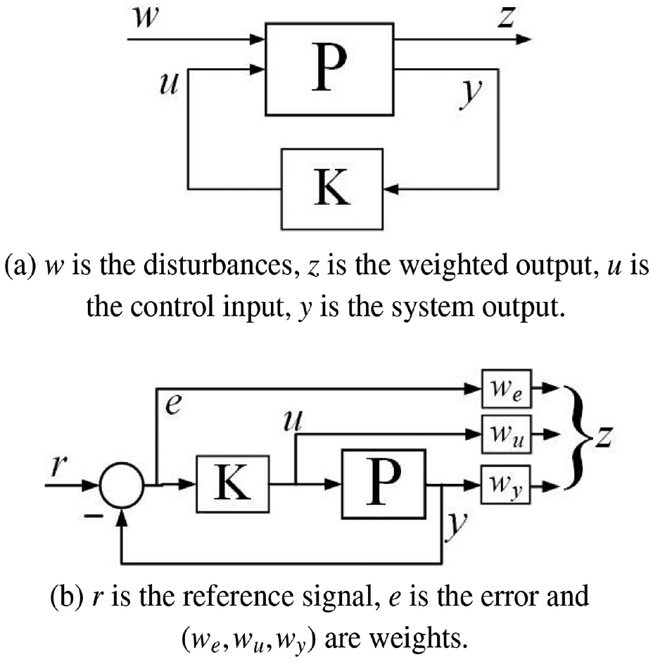
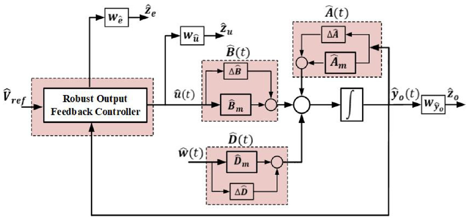
It is crucial for the control system to be robust against disturbances and parametric uncertainties. control synthesis since its inception by Zames (1981) has gone through many changes and advancements. Major advantages of this method are high disturbance attenuation, and stability increases. Therefore, this technique has been widely adapted to address numerous problems in control system engineering. The system under study in this paper is exposed to disturbances and uncertainties, for which a robust closed-loop controller can be designed. Various techniques are available in literature. One approach is to formulate a multi-objective, multi-input-multi-output (MIMO) system by applying signals weights to classical feedback control system Figure 2. The weights of the closed-loop is adapted to converge for certain design objectives.
A typical robust controller for plant P with feedback controller gain K and signals .
The controller objectives for our study are attenuation of disturbances and robustness to parametric uncertainties. There are two main sources of disturbances in the DGU (Figure 1(b)). One the intermittent nature of RES, second the variations in the connected load. RES interference causes disturbances at the input voltage, whereas load variations disturb the load current. The uncertainties present in the system are due to the variations in the DGUs parameters. To design a robust controller, We have to formulate a multi-objective,MIMO linear-time-varying (LTV) system that must accommodate disturbances and uncertainties. The multi-objective MIMO LTV system modeled in section below.
Multi-objective MIMO LTV system
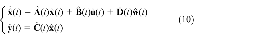
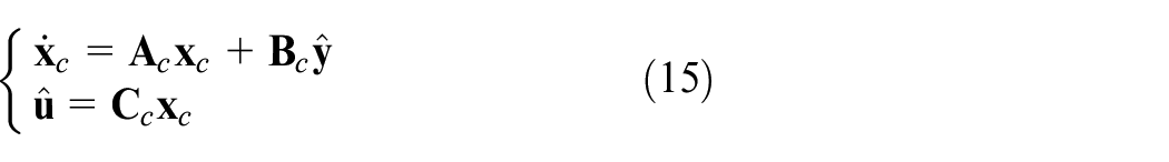
MIMO LTV system formulation for the N DGU system (10) is
where, is the state vector; represents the control input; is the external disturbance; is the controlled output; and denotes the measured output. Since there is no direct feedthrough from control input and disturbance to the output, we set . In addition, we suppose that disturbance vector is not present in penalty vector, hence we choose . The dimensions of the non-zero time-variant matrices are: , , , , , and .
Assumption 1: Let us define a set representing time-varying parameters of the MIMO system (11), , then the member is sum of the terms as below
where, is time-invariant mean valued matrix, calculated as , and is the row and column of the matrix . represents time-variant uncertainties, which is assumed to be structurally bounded and expressed as
where, the terms and are known real constant matrices. is the unknown Lebseque-measurable matrix-valued function, which is subject to the condition
Remark 1. Conditions (13) and (14) are admissible conditions and have been widely used to represent the parametric uncertainties in the control system (Kheloufi et al., 2013; Tandon and Dhawan, 2018).
Remark 2. The matrices and sizes agree for multiplication operations. From (13) and (14), the lower and upper bounds of can be shown as , here, .
Output-feedback control
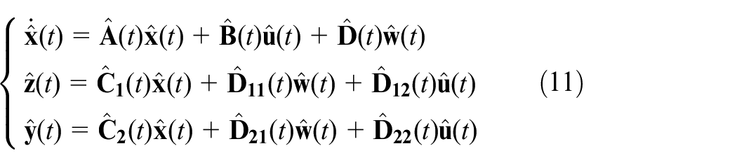
In this section we design the dynamic output-feedback controller for the DC microgrid system (11). The dynamical output-feedback controller is expressed as
where is state of the controller.
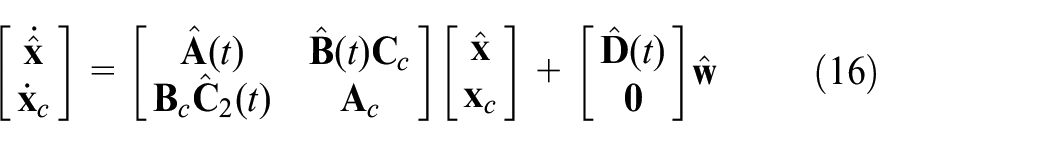
Applying the controller in (13) to the system in (11) we get the closed-loop system
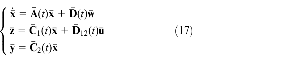
The MIMO LTV system of (16) is expressed as
were , , , , is the weights of the states, with ; is the weights of the control input, with , and is the output matrix.The weights selection of (17) depends on the system requirements.
control problem
Robustness of the controller requires to stabilize the microgrid in the presences of disturbances and parametric uncertainties. The robustness of the system (17) is guaranteed by considering the problem below:
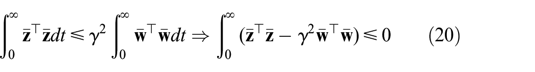
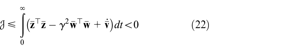
Problem 1: For the uncertain system (10) subject to Assumption 1, find conditions such that: 1) the closed-loop system (17) is asymptotic stable in the presence of all uncertainties and, 2) under the zero initial condition , for all nonzero the system should satisfy the inequality for robustness, and is a positive scalar constant.
Problem solution
For the LMI formulation of the proposed controller, we consider the problem conditions discussed in the preceding section. For Condition 1, which is the asymptotic stability of the output-feedback gain controller (15), from Lyapunov theory, we know that such controller exists if we could find a positive definite matrix , such that , and Therefore, by definition of , we have
Substituting (17) in (18)
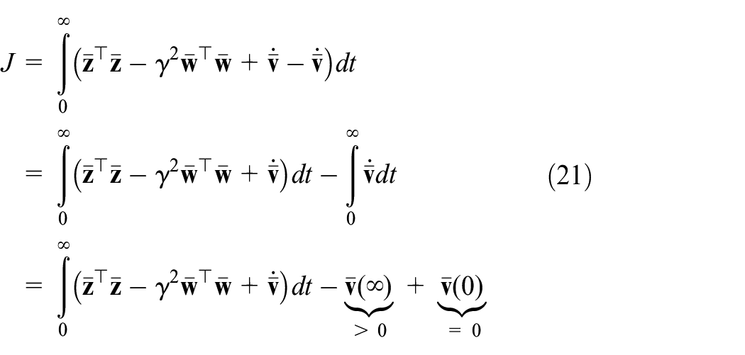
Condition 2 is the criterion, that is, . From the definition of norm; the criterion can be expressed as . Therefore
Provided that , then from equation (21) we can deduce that and hence criterion is guaranteed, therefore,
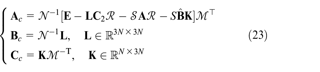
Theorem 1: From the inequalities (18) and (22) there exists a dynamic output-feedback controller such that the closed-loop system in (17) is asymptotically stable. The desired controller parameters are
here, and are non-singular matrices satisfying the following equality . The decision variables are obtained from solving the LMI minimization Problem 2.
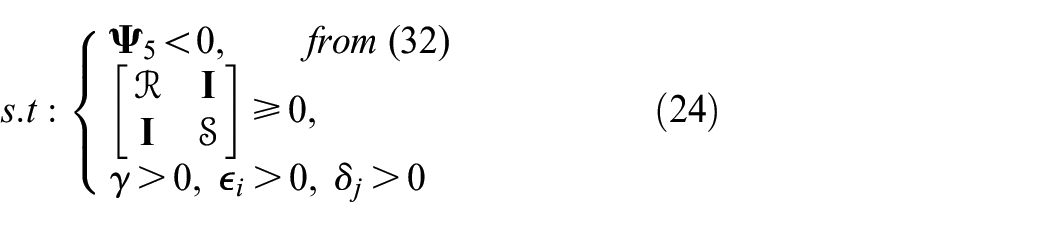
The desired controller parameters for output-feedback given in equation (23) is achieved by the minimization problem below.
Problem 2:
Results
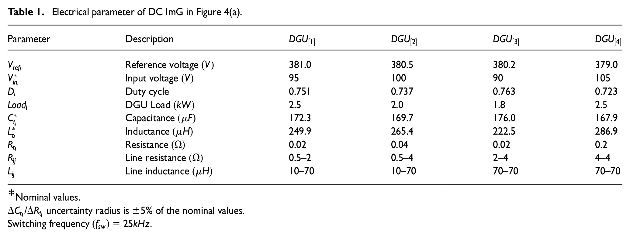
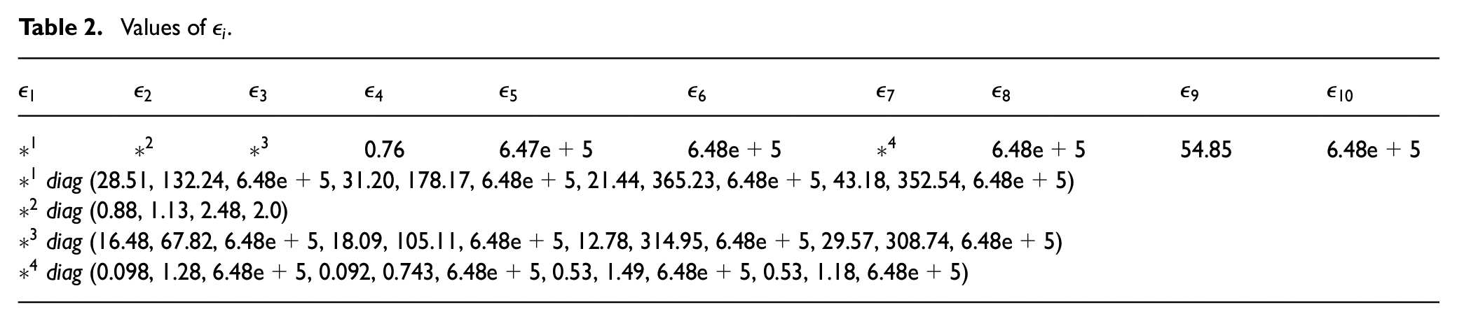
To study the performance of the proposed output-feedback controller, we consider the DC ImG with four DGUs as shown in Figure 4a. The microgrid’s electrical parameters are provided as Table 1. The minimization Problem 2 is solved in YALMIP interface for MATLAB where MOSEK is the solver (Lofberg, 2004; MOSEK, 2012). The weights in penalty vectors, Figure 3, are selected such that the LMI in Problem 2 is feasible and maintain small system oscillation. The system oscillation increases when small weights are considered for the voltage and current states; therefore, these weights are selected as , and . In the case of error state weight, smaller values result as slow response of the controller; to keep the system response fast, the error weight and integrator design parameter (8) are chosen to be and , respectively. The control effort weight is kept unity . From the minimization problem 2 we get , , , and . Table 2 shows the values of .
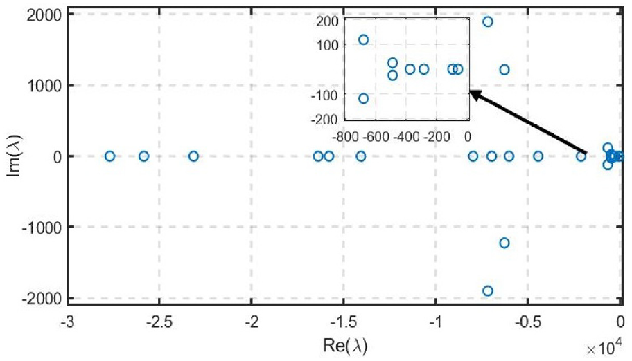
The proposed controller for N DGUs is shown in Figure 4(b). Robustness of the proposed controller is tested for the DC system in Figure 4(a) against unknown load disturbances, random disturbances in the source voltage, and parametric uncertainties. The closed-loop poles of the system under study is provided as Figure 5. For evaluation purposes, the performance of our proposed method will be compared with the decentralized control scheme proposed in Tucci et al. (2016) and the LQR controller. Details of each study scenarios are discussed in the following sub-sections.
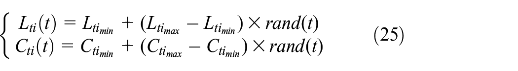
As the proposed controller is designed to be robust against parametric uncertainties, therefore, all of the case under study have time-varying parameters. The uncertain parameters randomly change value around the nominal values provided in Table 1. The following equations represent the random variation of parameters
where the minimum and maximum values of inductor and capacitor are of their nominal values given in Table 1; is a stochastic process with uniform distribution in the interval for any given time .
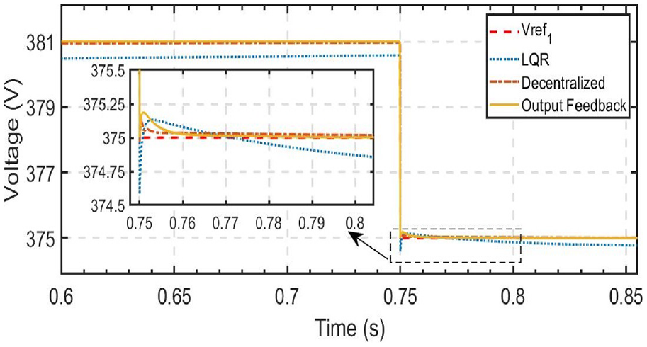
Reference voltage tracking
The reference voltage tracking capability of the controller is made part of the output-feedback controller as per error-dynamic (8). In this section, we asses the voltage tacking performance of the . Initially, the reference voltages of all DGUs are set according to Table 1. Moreover, no exogenous disturbances are considered in this case, therefore, the input voltages and output loads are kept constant. At , the reference voltage decreases from to . The response of is shown in Figure 6. In the zoomed-in plot, we find that the proposed method, as compared with the other controllers, has small settling time and maintains zero steady-state error. Therefore, the proposed controller has fast voltage tracking capability.
: Voltage tracking, changes from 381V to 375V at .
Robustness against unknown load changes
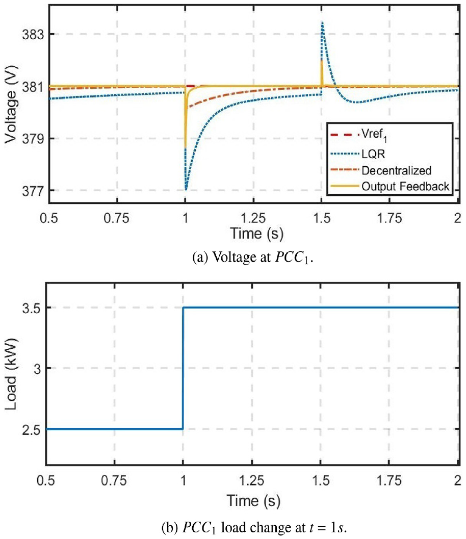
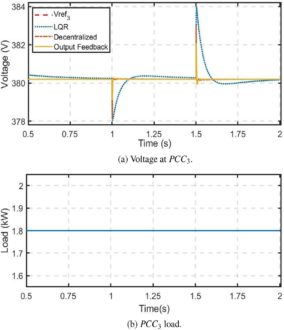
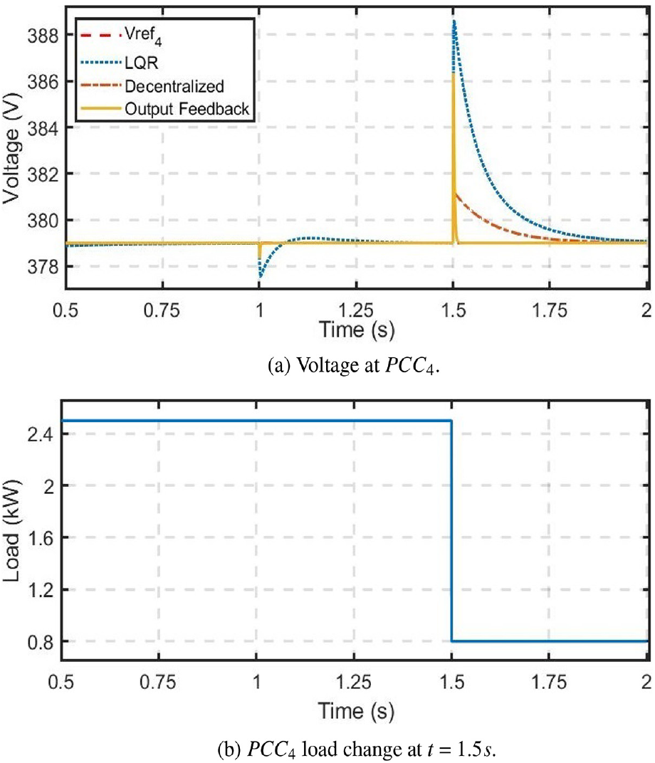
Robustness of the proposed output-feedback controller is tested against unknown load disturbances. The load change scenario is studied at two nodes of the microgrid (Figure 4(a)). The nodes are and . Initially, all the loads of the system considered are as per Table 1. At the load connected at is increases from to (Figure 7(b)).
robustness against load variation.
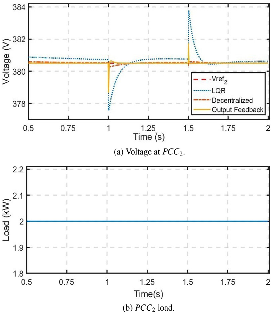
Opposite to the load increase at , the load at decreases to at (Figure 10(b)). The effects of these load changes on the output voltages of all the DGUs are shown in Figures 7a–10a. From the response of the load changes it can be observed from the PCC voltages that the proposed controller has smaller over and under-shoots in the case of load disturbances as compared to the LQR and the controller proposed in Tucci et al. (2016). In addition to the higher over and under-shoots, the LQR controller also has non-zero steady-state error. Therefore, the proposed controller is robust against load disturbances.
robustness against load variation.
robustness against load variation.
robustness against load variation.
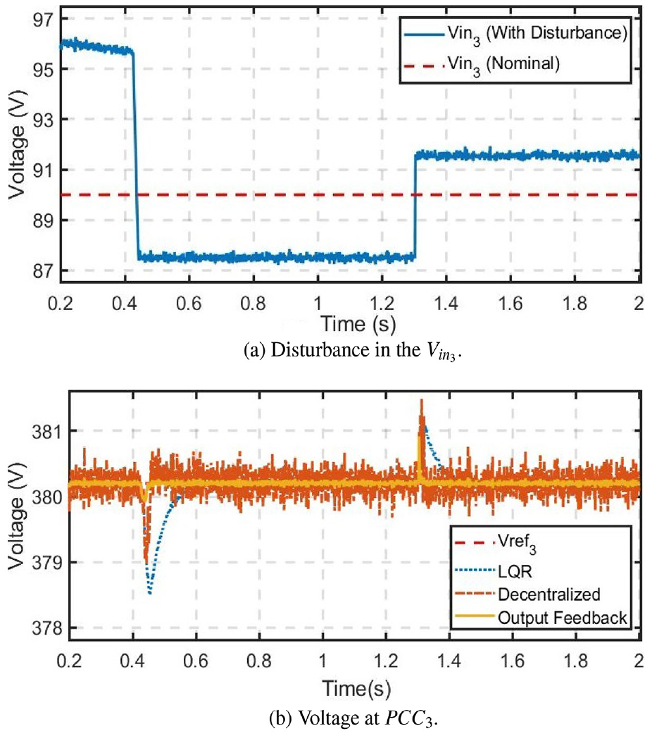
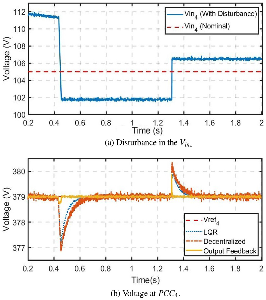
Robustness against source voltage disturbances
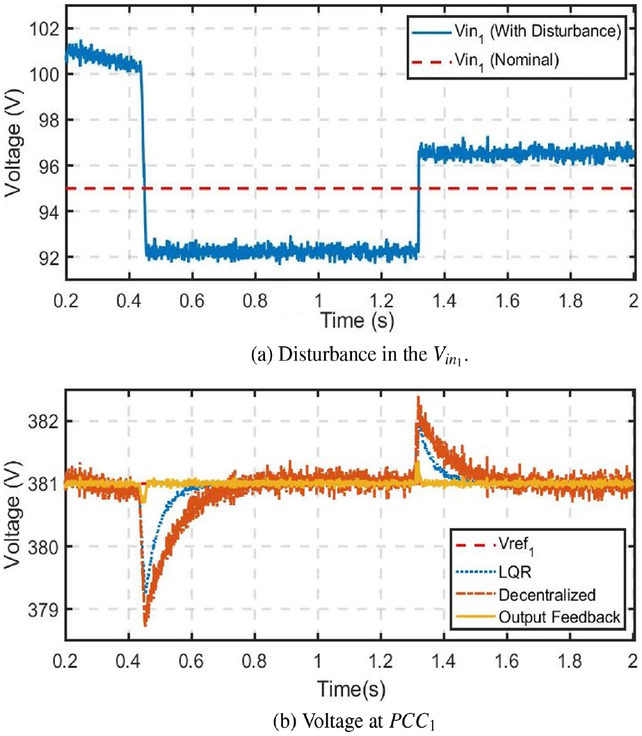
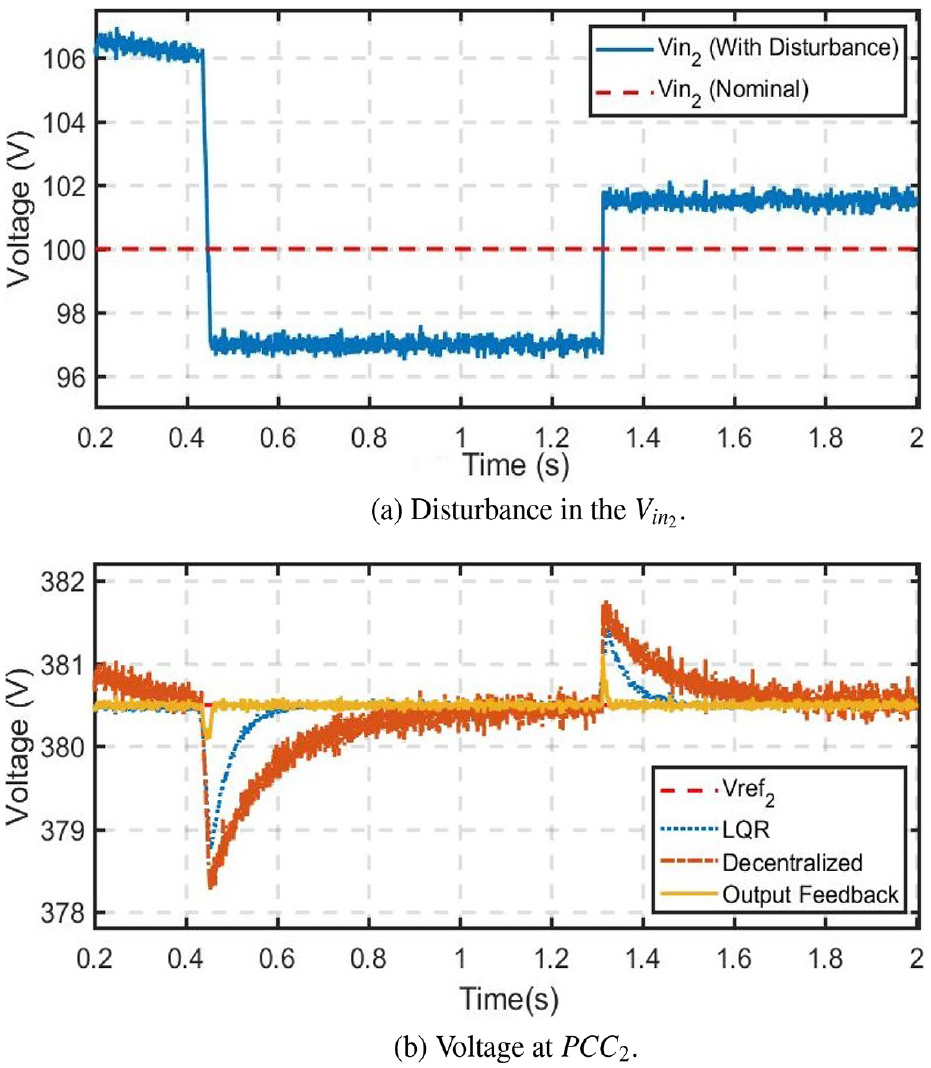
The sources of DC ImG are considered to be PV solar. The PV sources have variation. This behavior is emulated by introducing a random noise and voltage variations. These are added to the nominal voltage (Nominal). The nominal input voltage of each DGUs are set according to Table 1. The sub-figures (a) of Figure 11–Figure 14 show the disturbed input voltages as (with disturbance). The PCCs voltages are shown in sub-figures of Figures 11–14. The performance of the proposed controller is compared with the LQR controller and the controller proposed in Tucci et al. (2016). From the PCCs voltages, it is evident that the proposed controller substantial reduction in disturbances. Therefore, the control scheme has robustness against the input voltage disturbances.
robustness against source voltage disturbance.
robustness against source voltage disturbance.
robustness against source voltage disturbance.
robustness against source voltage disturbance.
Conclusions
In this paper, a novel robust output-feedback centralized controller has been proposed for a DC islanded microgrid (DC ImG). The proposed controller is designed to guarantee the closed-loop stability, reject the external disturbances, and be robust in presence of parameter uncertainties in the DGUs of the DC ImG. The exogenous disturbances are due to the variations in the RES voltage and load changes. Due to the presence of the uncertainties, the microgrid is modelled as a linear time-varying system. To design the controller, the overall LTV system is transformed into convex optimization control problem expressed as LMIs . The solution of the LMIs provided the sub-optimal parameters of the controller. To test the performance of the proposed controller, it is applied to a DC ImG test system consisted of four DGU. The DGUs has parametric uncertainties, and disturbances. The performance of the proposed control scheme is compared with the existing LQR and the decentralized controls in Tucci et al. (2016). The results show that the proposed controller is stable, has fast response, demonstrates robustness against the parametric uncertainties, and rejects the disturbances. The effect of the delay in the controller is important, therefore, future research work will consider it.
Footnotes
Appendix
In this section, some important mathematical lemmas that will be used in the proof of Theorem 1 are presented.
Declaration of conflicting interests
The author(s) declared no potential conflicts of interest with respect to the research, authorship, and/or publication of this article.
Funding
The author(s) disclosed receipt of the following financial support for the research, authorship, and/or publication of this article: This work was supported by the National Research Foundation of Korea (NRF) grant funded by the Korea government (MSIP) (No. 2018R1A2A1A05078680).
ORCID iD
Muhammad Mehdi
References
1.
AbdElhafezAForsythA (2009) A review of more-electric aircraft. In: 13th International Conference on Aerospace Science & Aviation Technology (ASAT-13), Cairo, Egypt, 26–28 May 2009, Paper No. ASAT-13-EP-01. Kobry Elkobbah, Egypt: Military Technical College.
2.
ArdjalAMansouriRBettayebM (2019) Fractional sliding mode control of wind turbine for maximum power point tracking. Transactions of the Institute of Measurement and Control41(2): 447–457.
3.
BeckerDJSonnenbergB (2011) DC microgrids in buildings and data centers. In: 2011 IEEE 33rd International Telecommunications Energy Conference (INTELEC), Amsterdam, Netherlands, 9–13 October 2011, pp. 1–7. NJ, USA: IEEE.
4.
BoydSEl GhaouiLFeronE, et al. (1994) Linear Matrix Inequalities in System and Control Theory, Vol. 15. Philadelphia, USA: SIAM.
5.
ChaouiHKhayamyMOmarN, et al. (2016) Adaptive control of DC-DC boost converters with parametric uncertainties and guaranteed stability. In: 2016 IEEE 25th International Symposium on Industrial Electronics (ISIE), Senta Clara, CA, USA, 8–10 June 2016, pp. 431–435. NJ, USA: IEEE.
6.
De DonckerRW (2014) Power electronic technologies for flexible DC distribution grids. In: 2014 International Power Electronics Conference (IPEC-Hiroshima 2014-ECCE-ASIA), pp. 736–743. IEEE.
7.
DouC-XZhaoFJiaX-B, et al. (2013) robust control of DC-AC interfaced microsource in microgrids. International Journal of Automation and Computing10(1): 73–78.
8.
DouCYueDGuerreroJM, et al. (2017) Multiagent system-based distributed coordinated control for radial DC microgrid considering transmission time delays. IEEE Transactions on Smart Grid8(5): 2370–2381.
9.
DragicevicTGuerreroJMVasquezJC, et al (2014) Supervisory control of an adaptive-droop regulated DC microgrid with battery management capability. IEEE Transactions on Power Electronics29(2): 695–706.
10.
DragičevićTLuXVasquezJC, et al. (2016) DC microgridspart I: A review of control strategies and stabilization techniques. IEEE Transactions on Power Electronics31(7): 4876–4891.
11.
ElsayedATMohamedAAMohammedOA (2015) DC microgrids and distribution systems: An overview. Electric Power Systems Research119: 407–417.
12.
EricksonRWMaksimovicD (2007) Fundamentals of Power Electronics. New York, USA: Springer Science & Business Media.
13.
HwangP-IJangGPyoG-C, et al. (2015) DC microgrid operational method for enhanced service reliability using dc bus signaling. Journal of Electrical Engineering and Technology10(2): 452–464.
14.
KhayatYNaderiMShafieeQ, et al. (2017) Robust control of a DC-DC boost converter: and techniques. In: 2017 8th Power Electronics, Drive Systems & Technologies Conference (PEDSTC), Mashad, Iran, 14–16 February 2017, pp. 407–412. NJ, USA: IEEE.
15.
KheloufiHZemoucheABedouheneF, et al. (2013) On LMI conditions to design observer-based controllers for linear systems with parameter uncertainties. Automatica49(12): 3700–3704.
16.
KimIHSonYI (2015) Robust cascade control of DC/DC boost converter against input variation and parameter uncertainties. In: 2015 American Control Conference (ACC), Chicago, IL, USA, 1–3 July 2015, pp. 2567–2572. NJ, USA: IEEE.
17.
KimIHSonYI (2017) Regulation of a DC/DC boost converter under parametric uncertainty and input voltage variation using nested reduced-order PI observers. IEEE Transactions on Industrial Electronics64(1): 552–562.
18.
KimMLeeSBaeS (2018) Decentralized power management for electrical power systems in more electric aircrafts. Electronics7(9): 187.
19.
KoB-SLeeG-YKimS-I, et al. (2018) A positioning method of distributed power system by considering characteristics of droop control in a DC microgrid. Journal of Electrical Engineering & Technology13(2): 620–630.
20.
LaiJLuXYuX, et al. (2017) Distributed voltage control for DC mircogrids with coupling delays & noisy disturbances. In: IECON 2017 – 43rd Annual Conference of the IEEE Industrial Electronics Society, Beijing, China, 29 October-1 November 2017, pp. 2461–2466. NJ, USA: IEEE.
21.
LeeB-SKimS-KParkJ-H, et al. (2016) Adaptive output voltage tracking controller for uncertain DC/DC boost converter. International Journal of Electronics103(6): 1002–1017.
22.
LiangHLiuZLiuH (2019) Stabilization method considering disturbance mitigation for DC microgrids with constant power loads. Energies12(5): 873.
23.
LiuYWangZLiuX (2007) Robust control for a class of nonlinear stochastic systems with mixed time delay. International Journal of Robust and Nonlinear Control: IFAC-Affiliated Journal17(16): 1525–1551.
24.
LiuZXieLBemporadA, et al. (2018) Fast linear parameter varying model predictive control of buck DC-DC converters based on FPGA. IEEE Access6: 52434–52446.
25.
LofbergJ (2004) YALMIP: A toolbox for modeling and optimization in MATLAB. In: 2004 IEEE International Symposium on Computer Aided Control Systems Design, New Orleans, LA, USA, 2–4 September 2014, pp. 284–289. NJ, USA: IEEE.
26.
MengLShafieeQTrecateGF, et al. (2017) Review on control of DC microgrids and multiple microgrid clusters. IEEE Journal of Emerging and Selected Topics in Power Electronics5(3): 928–948.
27.
MengQHouZ (2019) Data-driven multi-inverter cooperative control for voltage tracking and current sharing in islanded ac microgrids. Transactions of the Institute of Measurement and Control: 41(11): 3145–3157.
28.
MohamedAAElsayedATYoussefTA, et al. (2017) Hierarchical control for DC microgrid clusters with high penetration of distributed energy resources. Electric Power Systems Research148: 210–219.
29.
MorstynTMomayyezanMHredzakB, et al. (2016) Distributed control for state-of-charge balancing between the modules of a reconfigurable battery energy storage system. IEEE Transactions on Power Electronics31(11): 7986–7995.
30.
MOSEKA (2012) Mosek optimization software for matlab, version 6.0.
31.
NasirianVMoayediSDavoudiA, et al. (2015) Distributed cooperative control of DC microgrids. IEEE Transactions on Power Electronics30(4): 2288–2303.
32.
O’KeeffeDRiversoSAlbiol-TendilloL, et al. (2018) Voltage control of DC islanded microgrids: Scalable decentralised adaptive controllers. arXiv preprint arXiv:1801.04508.
33.
Oulis RousisATzelepisDKonstantelosI, et al. (2018) Design of a hybrid AC/DC microgrid using homer pro: Case study on an islanded residential application. Inventions3(3): 55.
34.
PapadimitriouCZountouridouEHatziargyriouN (2015) Review of hierarchical control in DC microgrids. Electric Power Systems Research122: 159–167.
35.
SadabadiMSShafieeQKarimiA (2017) Plug-and-play robust voltage control of DC microgrids. IEEE Transactions on Smart Grid9(6): 6886–6896.
36.
ShafieeQDragičevićTVasquezJC, et al. (2014) Hierarchical cevi’control for multiple DC-microgrids clusters. IEEE Transactions on Energy Conversion29(4): 922–933.
37.
ShiJYueDWengS (2019) Distributed event-triggered mechanism for secondary voltage control with microgrids. Transactions of the Institute of Measurement and Control41(6): 1553–1561.
38.
TandonADhawanA (2018) An LMI approach to non-fragile robust optimal guaranteed cost control of uncertain 2-d discrete systems with both state and input delays. Transactions of the Institute of Measurement and Control40(3): 785–804.
39.
TucciMRiversoSVasquezJC, et al. (2016) A decentralized scalable approach to voltage control of DC islanded microgrids. IEEE Transactions on Control Systems Technology24(6): 1965–1979.
40.
WangYXieLde SouzaCE (1992) Robust control of a class of uncertain nonlinear systems. Systems & Control Letters19(2): 139–149.
41.
YangYKarimiHRXiangZ (2013) Robust switching rule design for boost converters with uncertain parameters and disturbances. Abstract and Applied Analysis; 120543.
42.
ZamesG (1981) Feedback and optimal sensitivity: Model reference transformations, multiplicative seminorms, and approximate inverses. IEEE Transactions on Automatic Control26(2): 301–320.
43.
ZhangF (2006) The Schur Complement and its Applications, Vol. 4. New York, USA: Springer Science & Business Media.
44.
ZhangLBaiY (2008) On-line neural network training for maximum power point tracking of PV power plant. Transactions of the Institute of Measurement and Control30(1): 77–96.
45.
ZhaoJDörflerF (2015) Distributed control, load sharing, and dispatch in DC microgrids. In: American Control Conference (ACC), Chicago, IL, USA, 1–3 July 2015, pp. 3304–3309. NJ, USA: IEEE.