






Abstract
Optoelectronic tweezers (OET) utilizes the optically induced dielectrophoresis (ODEP) force to manipulate and assemble carbon nanotube (CNT) particles in an aqueous solution. This work can help us to gain exciting and promising applications in electronic devices and sensing areas. In this paper, a numerical model based on the Maxwell stress tensor (MST) method has been presented to study a single CNT particle subjected to both the ODEP force and torque in a non-uniform electric field. In addition, a single-sided OET, which is unlike traditional OET chips and enables the assembly and alignment of CNT particles, has been introduced and studied. The calculated results on the CNT particles analogy to non-spherical shapes demonstrate that the MST method can provide more accurate predictions than the effective dipole moment. Furthermore, both the DEP force and torque exerted on the CNT particle, as well as shell thickness, spatial position, and distance between CNT particle and electrode, have been studied in detail. These results are in agreement with those obtained by other researchers. This work can help us to gain new insights into the analysis of motions of the CNT particles suspended in OET chips.
Introduction
Extraordinary advances in carbon nanotube (CNT) particles have been widely utilized in biological, chemical, pharmaceutical, and optical fields such as bioelectronic noses (Lee et al., 2012; Son et al., 2015), antibody-nanotube cancer biomarkers (Lad and Agrawal, 2013; Yang et al., 2007), targeted drug delivery systems (Soldano, 2015), batteries (Huang et al., 2015), emitters (de Vega et al., 2016; Youh et al., 2016), Raman spectroscopies (Chatterjee et al., 2016), fiber sensors (Jiang et al., 2016), and gas sensors (Xu et al., 2018). As CNTs have a high aspect ratio, high mechanical strength, rich electronic properties, high thermal stability, and ultra-light weight, as well as enabling low-cost consumption, they are expected to lead to a reliable and multifunctional material for use in engineering applications (Baughman et al., 2002). With the development of CNT fabrication technologies and experimental systems, many manipulation technologies could be introduced into the rapid assembly, alignment, separation, and deposition to satisfy the specific and sensitive requirements. In the scenario presented here, there are a few mechanical technologies to achieve the manipulation of this matter at the micro- or nanoscale, including optical tweezers (OT) (Plewa et al., 2004; Shi et al., 2008; Xin and Li, 2014), dielectrophoresis (DEP) (Krupke et al., 2003; Li et al., 2004; Mathew et al., 2015; Sano et al., 2016; Shekhar et al., 2011), magnetic tweezers (Roberts et al., 2015; Tokarev et al., 2012), teslaphoresis (Bornhoeft et al., 2016), and thermophoresis (Nicholson et al., 2007).
Compared with these technologies, the dielectrophoretic force, generated by an applied non-uniform electrical field, is capable of spontaneously performing aggregation, sorting, and transportation based on the mature microelectromechanical systems manufacturing process (Luo et al., 2018). To the best of our knowledge, the development rate of DEP research based on literature and patents is faster than that of optical and magnetic techniques. In general, optical tweezers based on optical radiation forces have a high control accuracy, but most optical devices are expensive. Meanwhile, the magnetic force requires high current limits for its development in many experiments. It is imperative to note that many problems still exist regarding DEP technology. For instance, the relatively high voltage and media conductivities inside the channel and cavity may lead to electrode deformation because of electrochemical reactions (Martinez-Duarte, 2012). A disadvantage of designing electrode patterns is that a complex process line-up is required to improve the proximity of electrode structures. Herein, a novel manipulation technology known as optoelectronic tweezers (OET), which combines the flexibility of optical tweezers with the local large DEP, is presented to concentrate, sort, and transport cell colloids and particles (Hwang and Park, 2011).
To date, various experiments have been proposed to verify the ability to trap CNT particles by the OET chip. Pauzauskie et al. (2009) demonstrated that programmable optical electrodes generated by OETs enable the assembly of multi-walled carbon nanotubes (MWCNTs) using an optical power density 100,000 times less than single beam laser tweezers. Lee’s group (Lee et al., 2010) developed an OET platform to attract and move single-walled CNTs. Afterward, they developed a novel CNT-based sensor to measure the temperature and flow velocity of bio-samples within the OET platform (Hsu and Lee, 2014). Zheng et al. (2013) reported that image acquisition, image analysis, and light pattern generation modules were automatically used to assemble MWCNTs into arrays in the OET device. Moreover, a new process for fabricating polymeric electrodes based on a composite solution of conductive polyaniline particles and MWCNTs using optically induced DEP was presented by Liu’s group (Liu et al., 2014).
Thus, there is much interest in theoretical research on the motions of such CNT particles subjected to DEP forces. The numerical model provides not only a qualitative insight into the relation between the dimensions of CNT particles and experimentally controllable parameters such as frequency and fluid velocity, but also the design concept of electrodes in characterizing the electric fields prior to fabrication. Dimaki and Boggild (2004) built a DEP model of SWCNTs to calculate the capturing probability, assembly time, and separation efficiency for both metallic and semiconducting nanotubes. The concentration of CNTs was studied with reference to the applied voltage, electrode gap, and duration based on the effective dipole moment (EDM) method by An and Friedrich (2009). Meanwhile, the simulation results were consistent with the experiments. Lu et al. (2009) suggested that comb electrodes exhibit a better position control of SWCNT assembly compared to the parallel electrode in the numerical solution. In addition, three mechanisms including CNT rotation, CNT-to-CNT, and CNT migration were investigated by a set of three independent nonlinear differential equations by Olica-Avilés’s group (2012, 2014). Berger et al. (2015) recently presented a method for simulating the motion and behavior of CNTs using three-dimensional electrostatic finite element analysis to predict the effect of CNTs on the electric field and its elastic deformation. Summarizing the above, there is little theoretical concern on the manipulation of CNTs with respect to OET chips. Even though OET technology possesses the advantages of traditional DEP, the electric properties of photoconductive layers are still different from metal electrodes. Therefore, the frequency characterization that determines either the positive or negative DEP force direction should be reconsidered carefully. According to the DEP force calculation, the effective dipole moment and Maxwell stress tensor (MST) methods have been used to perform a comparison and analysis to understand the different DEP models. The change in shell thickness, spatial position, and electrode distance are studied to find useful information in the DEP manipulation. This work is valuable to nanotechnology investigations and applications.
Following the Introduction, this paper is structured as follows. In Section two (theory and model), general principles of dipole polarization and MST approaches that are considered when calculating DEP forces generated by illuminated light spot are discussed. Section three (simulation and discussion) illustrates different vital efforts, which includes effective dipole moment and MST, solution conductivity, shell thickness, CNT position, spot radius, orientational torque, and a pair of parallel spots. Finally, concluding remarks are made at the end.
Theory and model
There are several types of forces exerted on CNT particles in the micro-environment under natural conditions, such as gravity, Brownian, and van der Waals, among others. As described by Liu et al. (2014) and Olica-Avilés et al. (2014), DEP and fluidic drag forces are dominant when an applied non-uniform electric field exists. In general, the motion of such particles experiencing DEP forces results in the appearance of fluidic drag forces, which are opposite to the direction of particle motion. It is assumed in this study that the DEP and fluidic drag forces are equal in the steady state. For the sake of simplicity, it is essential to note that the effect of AC electroosmosis and electrothermal flow can be neglected at higher applied frequencies (>10kHz) and weak optical power (<100mW/cm2) to focus on the study of single CNT particles experiencing the DEP force. The calculation method of DEP is mainly classified into two approaches including the effective dipole moment and MST, as described below.
Effective dipole moment
Owing to Pohl’s outstanding work, the effective dipole moment is well known as an approximate solution to predict the experimental results (Baughman et al., 2002; Plewa et al., 2004; Shi et al., 2008). The shape of a particle is considered as an ellipsoid, as shown in Figure 1.
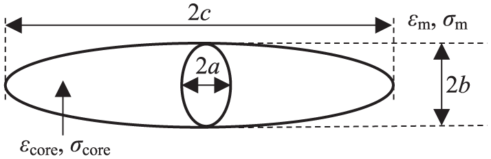
2D schematic of MWCNT particle with one shell of uniform thickness δ suspended in the solution.
Thus, the time-averaged DEP force is expressed in equation (1)

where εm is the permittivity of the medium and V is the MWCNT volume (V=4πabc/3, where a, b, and c are semi-axis lengths at x, y, and z directions, respectively). The parameter

where ε* is the complex permittivity equal to ε*=ε-jσ/ω (ω is the angular frequency of the electric field, σ is the electric conductivity, j is

In equation (3),

where
Similar to the DEP force vector, the torque

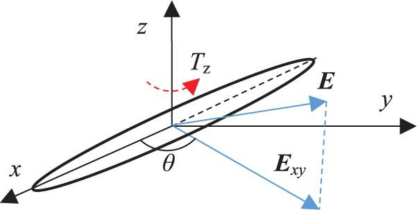
CNT particle aligned with the longest axis parallel to the component of the electric field
where

In equation (6), θ is the angle between the longest axis of the CNT and the direction of the electric field Exy. Here, the subscripts x, y, and z are ordered according to the convention of the right-handed coordinate system, that is, x→y→z→x.
MST
Among the DEP force calculation regarding a non-spherical particle, the MST approach is considered a robust method for simulating the behavior of particles using the arbitrary Lagrangian–Eulerian model. Furthermore, the results of particle trajectories are in good agreement with the experimental observations (Ai et al., 2014; Kumar and Hesketh, 2012; Weng et al., 2016). The MST expression is given by equation (7) (Shih et al., 2015)

where

Here,

where
Simulation and discussion
The photoconductive layer is arranged between the insulating and conductive layers serving as the binary gate in the presence of both the light pattern and bias voltage. The photo-induced carriers could result in an increase in conductivity of the photoconductive layer in the region with light illumination. Thus, the voltage decreases the most in the medium layer to induce the polarization of particles, causing the particles to move towards or away from the light spots at specific frequencies. Considering the material of hydrogenated amorphous silicon, the thickness and permittivity of the photoconductive layer are 1μm and 11.7ε0 (ε0=8.854×10⁻¹²F/m is vacuum permittivity), respectively. In addition, its conductivity with and without light illumination are 10−3S/m or 10−6S/m, respectively. The electric field can be obtained by solving the Laplace equation given in equation (10)

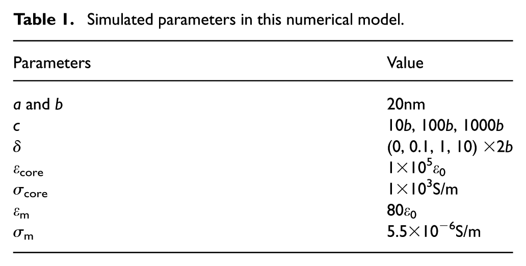
As the wavelength of the electric field is normally several orders of magnitude larger than the dimensions of the device, the quasi-static approximation can be used. The electric properties and dimension of the CNT particle are summarized in Table 1 referring to Olica-Avilés et al.’s (2014) data. The bias configuration of the model used in the simulations is plotted in Figure 3. The virtual electrode with a 2.5μm radius could be generated by digital micromirror device or liquid crystal display devices (Hwang and Park, 2011). In the region with light illumination, a high conductivity of 10−3S/m is chosen and vice versa.
Simulated parameters in this numerical model.
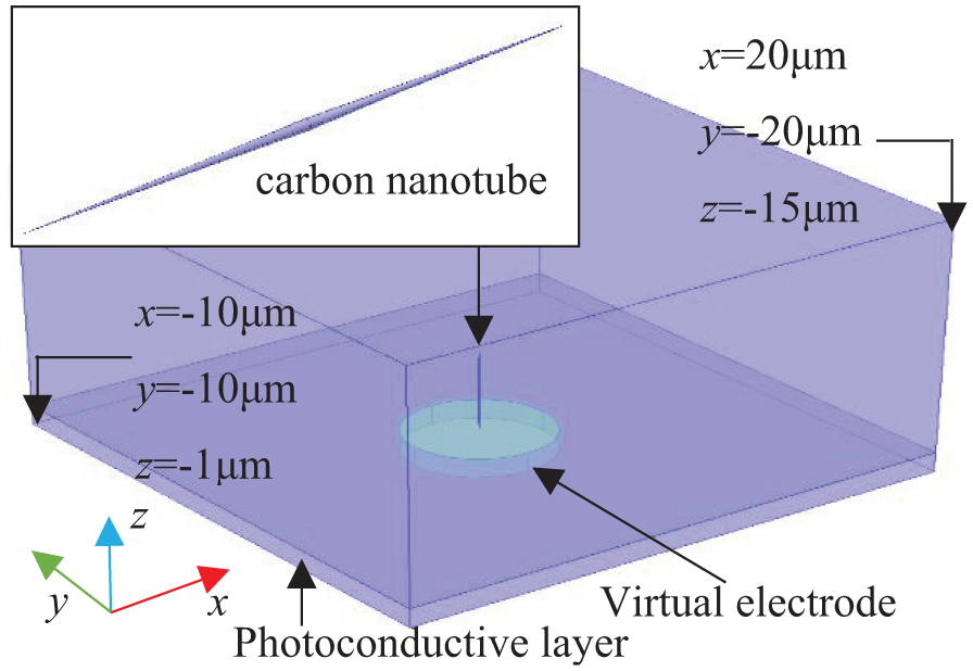
Schematic of numerical model for DEP force exerted on single CNT particle.
The bias voltage V=20Vpeak-to-peak is applied between the top and bottom boundaries, which are of the same order of magnitude as that used in the experiments (Liu et al., 2014; Zheng et al., 2013). The research on the CNT particle that is subjected to the DEP force is described in detail below.
Effective dipole moment and MST
Both the effective dipole moment and MST methods are studied assuming that the centroid position of this CNT particle is at the (0, 0, 2μm) location. In terms of equations (1) and (8), three component forces Fx, Fy, and Fz are obtained in a range of frequencies from 103 to 107Hz, as shown in Figure 4. The results indicate that both methods exhibit an identical trend of change. However, the force Fz that is based on the EDM method is weaker than the MST at low frequencies. The advantage of the EDM method is its simple and intuitive calculation without considering the effect from the suspended particle distorting the electric fields due to the neglect of the higher-order moments.
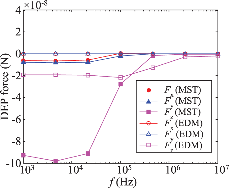
Comparison between EDM and MST methods for CNT particle close to the optical spot.
As described by Kumar and Hesketh (2012), the electric potential and field gradient is obtained at the centroid position of the CNT particle in the medium, by ignoring the real solid particle and replacing its volume with liquid instead. In contrast, the CNT particle placed at the medium layer is calculated by MST while studying the electric potential and field distribution. The method for around the particle surface is evaluated by post-processing these quantities and integrating them to evaluate the DEP force on the particle. It is imperative to note that there are non-zero x and y component forces at low frequencies with the MST method. The direction of the DEP force is determined by the conductivities of the particles at medium low frequencies. As the edge between light and dark has the greatest gradient change of electric field strength, the x and y component DEP forces in the horizontal direction intend to repel it to this area.
However, the forced direction has random characteristics depending on the mesh quality. When we attempt to reduce the maximum mesh element, both x and y component DEP forces are positive. In addition, the results indicate that the manipulation of the CNT particle is not supposed to utilize higher frequencies (>100kHz). Assuming that the CNT particle vertically moves away from the optical spot at the height of 10μm, it is found that the DEP forces dramatically decrease with height using either method, as shown in Figure 5. This error between the EDM and MST method is reduced due to the decrease in higher-order moment in the weak electric field strength.
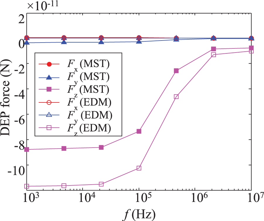
Comparison between EDM and MST methods for CNT particle away from the optical spot.
Effect of aqueous solution conductivity
Apart from the applied frequency influence, the conductivity of the medium should completely be considered in this work. Herein, three different conductivities of the medium are individually calculated based on the MST approach, as shown in Figure 6.
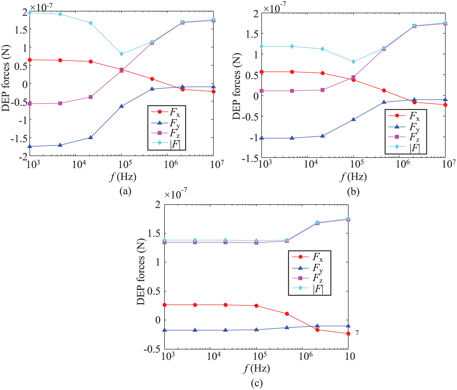
DEP force components at aqueous conductivities of (a) 2.0×10⁻⁵, (b) 1.74×10⁻⁴, and (c) 2.0×10⁻³S/m.
The CNT particle is placed at the (2.5μm, 0, 2μm) position at the edge of the optical spot to study the x- and y- direction component forces. Figure 6 indicates that the total DEP force exhibits no significant change at a range of frequencies. This x component force Fx exhibits a repulsive force (i.e. negative DEP), causing the particle to move away from the optical spot at low frequencies, whereas, the force could attract the particle into the optical pattern area at frequencies up to 100kHz. In this case, the component force Fy is still an attractive state that is weaker than the forces Fx and Fz. As for the 1.74×10⁻⁴ and 2.0×10⁻³S/m conductivities, the force Fz that is negative does not vary with the applied frequencies. This simulation implies that the low conductivities of the medium should be employed for the enrichment of CNT particles.
Effect of shell thickness
It is essential to research the thickness of the shell that affects the dielectrophoretic polarization. As described by Kumar and Hesketh’s (2012) investigation, they reported the importance of the surface dominant properties of nanostructures in the DEP manipulation and assembly (Kumar and Hesketh, 2012). Therefore, the thickness effect can be considered in our model. The shell uniformly and completely covers the core of the CNT particle. The permittivity εlay and conductivity σlay of the shell are 104ε0 and 10−4S/m, respectively. The relative data from position of the particle and electrical conductivity are similar to Figure 6 (a). Figure 7 shows the component forces for two different shells based on the MST method. By comparison with the CNT particle without the dielectric layer, the total DEP force decreases with applied frequency. This demonstrates the manipulation of the CNT particle at low frequencies in many of the OET experiments (Hsu and Lee, 2014; Lee et al., 2010; Liu et al., 2014; Zheng et al., 2013). Increasing the thickness of the shell reduces the x- and y- directional component forces because the increased volume results in the polarization effect induced by the vertical electric field along the z-axis direction.
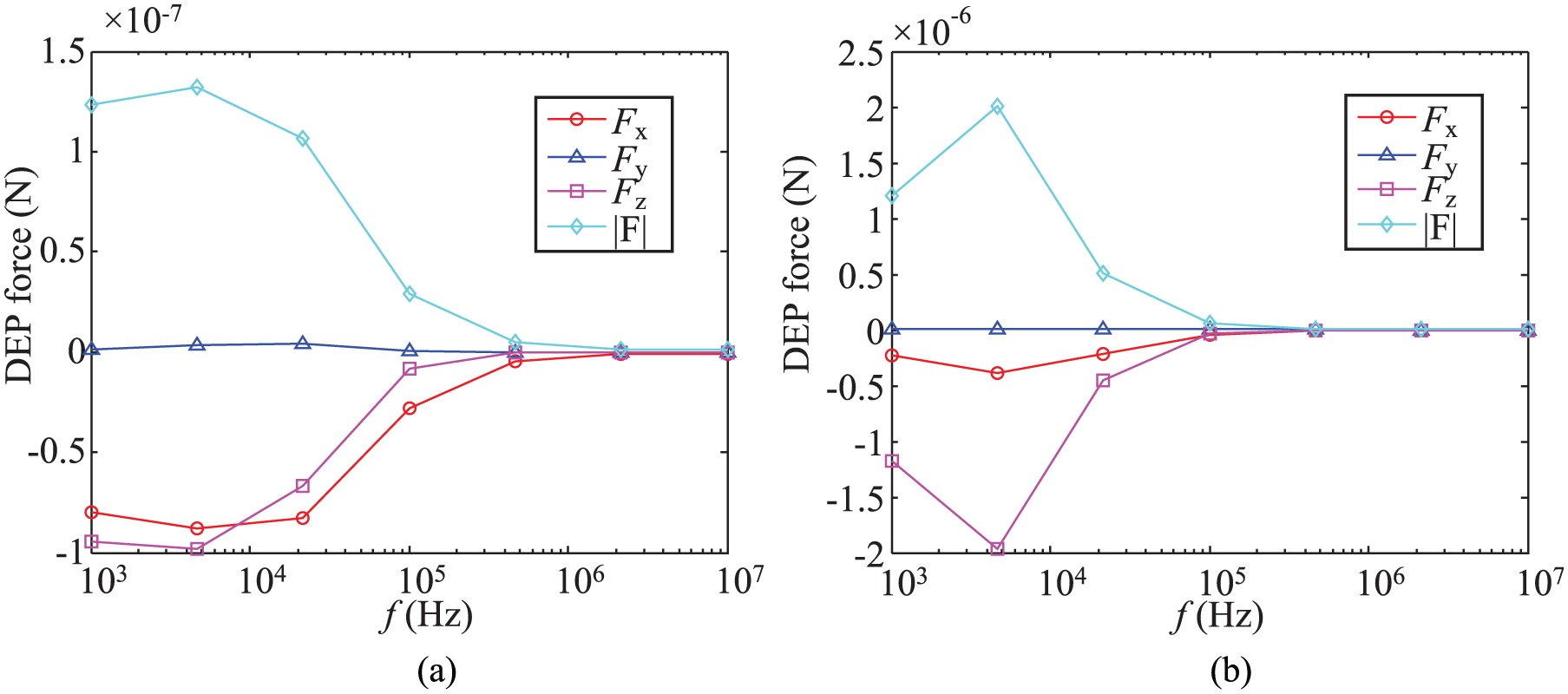
DEP force for thickness of (a) 20nm, (b) 200nm.
CNT position and optical spot radius
According to equation (1), the DEP depends on the spatial distribution of electric field strength. Thus, the results of the CNT particle without dielectric layer and optical spot radius are plotted in Figure 8. The DEP force exerted on the CNT particle at the center of the optical pattern decreases dramatically when it is higher than 3μm. Increasing the radius of the optical pattern could cause reduction in the non-uniform electric field. Hence, a smaller size-dependent light pattern and intensity that improves the induced electric field should be discussed. We found that the 3D structure of the metal- and carbon-electrodes (Islam et al., 2016; Jia et al., 2015; Martinez-Duarte et al., 2011) is a good advantage for manipulating the particles suspended in the larger area. It is important to study the fact that the 3D photoconductive layer can manipulate the CNT particles.
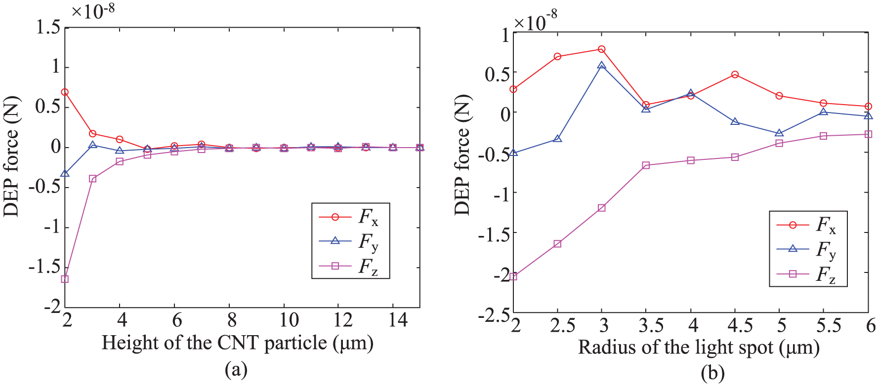
DEP force referring to the spatial electric field due to the (a) height of CNT particle and (b) radius of optical spot.
Orientational torque of CNT particle
Prolate polarizable particles respond to an electric field by aligning their longest axis parallel to the field vector. Apart from their geometric characteristics, the frequency-dependent orientation is an important factor because the measurement of the orientational spectra of elongated cells such as certain erythrocytes and bacteria provides a means to study the dielectric properties of these cells (Jones, 1995). The CNT particle is placed at the (0, 0, 2μm) location similar to that in section Effective dipole moment and MST.
Moreover, the particle rotates clockwise about the rotation center y-axis and the angle between the longest c axis and z-axis is 45°, as shown in Figures 9(a) and (b). In accordance with equations (6) and (9), the torque is plotted in Figure 9(c). It is found that the torques Tx and Tz are zero because their polarization moments are parallel to the component of the electric field. The Ty torque is proportional to the z-axis component of the DEP force because of the strong electric field and vertical direction. The torque Ty that is based on the MST method is still greater than the effective dipole moment in correspondence with the DEP forces. It is clear that the shell thickness of the CNT particle is an important factor from the section effect of shell thickness. Thus, research on the orientational torque for the layered CNT particle is essential if one assumes that both the electric properties and geometric position are similar to those in section (Effect of shell thickness). Figure 10 indicates that the torque Ty increases with the shell thickness, reflecting the weak torques at higher frequencies (>100kHz).
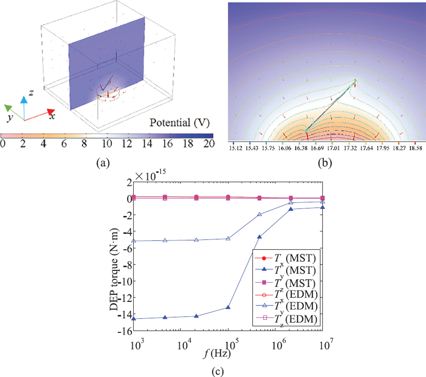
Orientational torque acting upon the CNT particle regarding (a) electric field distribution, (b) cross-section of xz plane, and (c) torque comparison between effective dipole moment and MST methods.
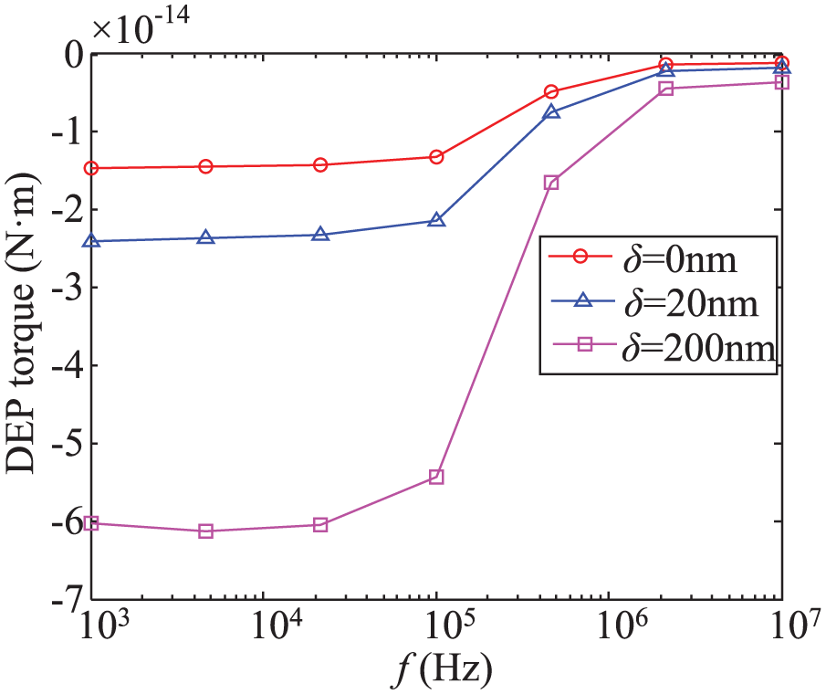
Thick effect of CNT particle exerted by the torque Ty. A negative Ty (torque about the y-axis) indicates clockwise rotation and vice versa.
Study on a pair of optical patterns
In Lekner’s studies (2014), he has already indicated that torque acting on the cylinder pair always acts to align them with the electric field. As can be observed in Figures 9(b) and (c), the torque generated by the induced light pattern attempts to twist the CNT particle perpendicular to the substrate approximated to an uncharged conducting cylinder. In general, parallel electric fields in many experiments (Burg and Poulikakos, 2011; Knaapila et al., 2014; Xu et al., 2009) are always employed to manipulate the CNT particles for the large-scale fabrication of functional electronic circuits. Ohta et al. (2007) presented a novel OET structure with a modified single-sided photoconductive layer providing an electric field parallel to the plane of the chip. The fabrication of OETs is only slightly more involved than the above-mentioned traditional OET with the top and bottom electrodes. Chemical wet-etching technology is used to divide the photoconductive thin film. Towards this end, the distance between the two photoconductive thin films at the same height is assumed as 5μm in our simulation, as shown in Figure 11(a).
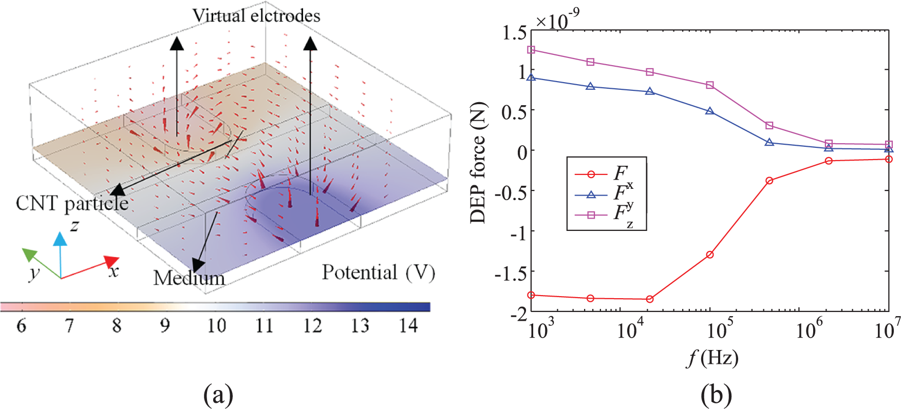
DEP force acting on the single-sided OET: (a) CNT suspended in medium subjected to the parallel electric field and (b) three torques using MST.
Meanwhile, the CNT particle without the dielectric shell is retained at the (0, 0.1μm, 0.1μm) location. The angle between the longest axis and x-axis is 80°. Figure 11(b) shows the DEP forces exerted on the CNT particle. The negative DEP force Fx causes the CNT particle to move away from the virtual electrode. In fact, increasing the conductivity of the medium to 2.0×10⁻³S/m generates the positive DEP force that attracts it, as described in section 3.2. In Figure 12 (a), the direction of the electric field using the single-sided OET is approximated to the parallel metal-based electrodes. The torque Tz is greater than the others, as shown in Figure 12 (b), and the torque strength increases with the decrease in orientational angle; meanwhile, both Tx and Ty are independent of the angle. As the virtual electrodes based on the photoconductive thin film are different from the normal metal electrode, the other two torques have non-zero values. It seems that, as a result, the CNT particle is pointed towards the edge of the photoconductive thin film.
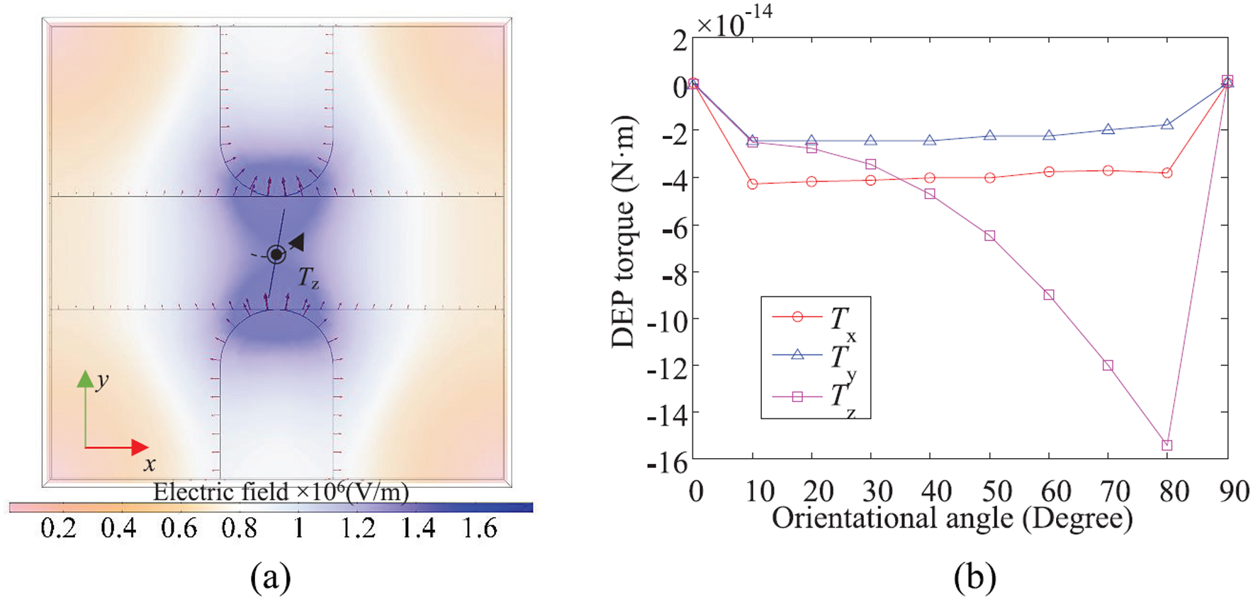
Torque acting on the single-sided OET: (a) Cross-over section of substrate with respect to electric field, (b) Torque of CNT particle.
Conclusion
In this paper, we present numerical model used to study a CNT particle that was subjected to ODEP. Full 3D ODEP simulations were performed to compare the effective dipole moment and MST methods, and to gain additional insights into the ODEP phenomena in CNTs. The results, including the medium conductivity, shell thickness, particle position, and optical pattern size, were in agreement with those obtained in previous studies. However, further research is needed to build a better mesh quality of such an elongated CNT particle with a high aspect ratio to reduce computational power, especially for nanoscale thicknesses. In addition, the single-sided OET considered in the numerical model was demonstrated to be eligible for manipulating the CNT particle parallel to the substrate to fabricate electronic devices or sensors. The present model based on the MST method not only provided accurate solutions for both the DEP forces and torques in the OET, but is also expected to enable real dynamic simulations contributing to the Arbitrary Lagrangian-Eulerian approach.
Footnotes
Declaration of conflicting interests
The author(s) declared no potential conflicts of interest with respect to the research, authorship, and/or publication of this article.
Funding
The author(s) disclosed receipt of the following financial support for the research, authorship, and/or publication of this article: This work was supported in part by the Youth Foundation of Hebei Province under Grant F2017501059 and F2018501063, the Doctoral Scientific Research Foundation of Liaoning Province under Grant 20170520325 and the Fundamental Research Funds for the Central Universities under Grant N172304033.