






Abstract
Due to the concern with energy emergencies, the energy obtained from the sunlight is considered as the most capable conventional resources. Hence, the maximum power point tracking approach is necessary for obtaining the enhanced efficiency from the solar panels. In the case of direct current (DC) application, the output obtained from the photo-voltaic (PV) array cannot be directly connected to the electronic devices. For regulating the output from the PV array, the DC-DC converter is provided in between the load and the array. The converter design plays a significant role to track the maximum power point of the solar panel. This paper describes the design of three converters, namely the boost, buck-boost and buck converter, along with the fuzzy logic controller. It varies the time for switching ON and OFF of the converter concerning changes in the solar panel power. The result of converter power and solar panel for different irradiation is compared for various DC-DC converters. The fuzzy logic controller is employed in the generation of optimal control pulse for the DC-DC converter. Moreover, in the solar photovoltaic system, the steady-state operation is performed and the various solar irradiance results are analyzed. The proposed approach is compared with the various DC-DC converters like buck-boost converter, buck converter and boost converter to prove the efficiency. Then, the performance analysis of the current, voltage and power of PV is analyzed.
Keywords
Introduction
Among the sustainable power resources, the photo-voltaic (PV) energy obtained from the solar panel is considered as the most essential and reasonable asset due to its prevalence, maintainability and is found widely all over the world (Bingül and Karahan, 2011, 2012). The yield qualities of the PV module rely upon the voltage, irradiance and cell temperature of the solar array. Meanwhile, the solar array generates nonlinear qualities and it becomes necessary in demonstrating those non-linearities that are utilized in tracking the maximum point of the solar framework applications (Ambikapathy et al., 2017; Sangwongwanich and Blaabjerg, 2019; Sankar et al., 2019; Seyedmahmoudian et al., 2018). The maximum power point tracking (MPPT) algorithm is employed in extracting the maximum power from the working environmental conditions, like cell temperature and irradiance. The modification of the impedance value is determined by the PV and load that are employed in changing the non-linear characteristic curve. Due to the quick variation of insulation, the non-linear characteristic of PV current-voltage seems to be complex in evaluating the MPPT (Bounechba et al., 2014; ; Hua and Shen, 2002; Padmanaban et al., 2019; Shahid et al., 2018; Sundaraj et al., 2020).
In general, the maximum power point (MPP) has the capability of supplying the maximum power from the solar PV array at a specific point, which further leads to an efficient production of electricity. The MPP comprises of a non-linear locus point that accordingly diverges its cell temperature and solar irradiances. In order to enhance the system efficiency, from the solar photo voltaic panel it is necessary to track the power from the MPPT. The power obtained from the PV panel employs in enhancing the optimization processes. Numerous approaches such as perturb and observe (P&O) approach, incremental conductance (INC) are established broadly to track the MPPT. Recently, one of the well-known techniques known as the fuzzy logic (FL) control-based MPPT strategies is used for PV (Chin et al., 2011), due to its simplicity and imprecise inputs. With the utilization of fuzzy logic control (FLC), the maximum power is obtained under varying climatic conditions. The duty cycle of the boost converter provides the output of FLC. By modifying the duty cycle of boost converter, the maximum power can be accomplished. The inverter is used in the conversion of direct current/alternating current (DC/AC), which drives the load. The issue of the ideal coupling between a PV generator and a charge type ceaseless is not yet truly tackled. A mechanical obstruction that exists in this kind of coupling develops an issue while transmitting extreme energy from the solar generator, which regularly experiences poor adjustment. The working point coming about is then here and there exceptionally a long way from the most MPP. The literature gives a lot of arrangements on the control calculation that looks through the most maximum power moment that the global photo-voltaic (GPV) is coupled to a load through a static converter. In recent years, evolutionary methods have been achieved better performance for engineering applications (Sundararaj, 2019a, 2019b; Sundararaj et al., 2018; Vinu, 2016).
In this work, we propose new MPPT control with the assistance of different DC-DC converters regularly for PV frameworks. The main objective is to establish an approach to obtain energy from the PV panel. For that process, the various DC-DC converter is designed with FLC so as to achieve the enhanced energy from the solar array. Besides, it analyzes two diverse variances namely normal and solar irradiance variance (i.e., partial shading conditions). To provide implementation simplicity of the PV system with load, the proposed approach is designed with three different types of converters namely buck-boost, buck and boost converters. Then, the detailed analysis of the proposed approach is specified in Section 3.
The rest of the paper is organized in the following sections. The past literal works based on various converters are described in Section 2. Section 3 describes the mathematical model of solar panel and converter designs. The proposed controller is proposed in Section 4. Section 5 concludes the paper.
Review of related works
This section provides numerous research works that are focused based on the fuzzy-based buck, boost and buck-boost converters thereby tracking the maximum power from the MPPT. In order to gain a better understanding, several relevant research areas and its related works are summarized in the following section.
Numerous DC-DC converters are employed in the solar PV array to extract the MPPT. PV system with boost converters is employed recently in extracting the maximum power by changing the value of the duty cycle (Upadhy et al., 2014). Venkatesan et al. (2018) determined an inter-weave boost converter to reduce the enhanced-recurrence voltage swell presented weigh in the board. Consequently, the capacitor with very high life expectancies is chosen. Besides, film capacitors that are dependent upon the voltage swell are also chosen. The study was completed for ascertaining voltage swell that forces the PV module to choose the input filter more exactly. Upgraded energy generates the PV that was scientifically demonstrated and tentatively illustrated. Yilmaz et al. (2018) carried out the fuzzy logic MPPT technique for boost converter fed PV. Then, the proposed approach is verified for different temperatures and irradiance conditions. The buck converter acts as a charge controller with the help of the proportional integral (PI) controller. Also, there occurs nonlinearity among the characteristics of voltage, and current since they rely upon natural conditions. Two conventional strategies, constant current (CC) and constant voltage (CV) strategies, are utilized in charging the battery. Low consistency voltage and current are required for quick accessing with very less loss. PI control is considered as one of the steady-state techniques that are employed in further examination. PI control was created and a straightforward system in providing an agreeable outcome.
Ozdemir et al. (2017) mentioned the high step-up ratio to get the MPPT with the FLC fed quadratic boost converter. To make the converter reference signal, the FLC was used and accomplished with a low duty cycle ratio. The efficiency of MPPT in PV was obtained as 99.10% and additionally, the yield control swaying of the converter. In addition to this, few immediate MPPT was characterized based on the strategy with a change in the direction variable. Hence, fixed-advance MPPT calculations and variable-advance MPPT calculations were separated. As per the homogeneous irradiance or non-homogeneous irradiance, there are a few works that manage the partial shading of the solar energy sources.
Normally, the P&O methods were employed in enhancing the energy from PV under uniform insulation condition (UIC) (Algazar et al., 2012; Saravanaselvan et al., 2014; Upadhy et al., 2014). Be that as it may, this displays variance around the most extreme power point amid enduring state activity, which includes power loss control. Traditional strategies – for example, hill climbing strategy, INC, open-circuit voltage and the load voltage/current enhancement procedure – are utilized when just one peak is available in the PV arc (Chin et al., 2012). Since most of the MPPT strategically approaches were distributed in 1960, all over the world that furthermore enumerates more than 15 MPPT strategies. They can be characterized by utilizing the steps and procedures of the maximum power point that comprises two different types of techniques: direct and indirect techniques. In addition to this, the indirect techniques are further classified into a short circuit and open circuit that requires an earlier assessment of the PV. This indirect technique also depends on numerical connections or databases, not to legitimate all working environmental conditions (Chandra et al., 2018; El Khateb et al., 2014; Tey et al., 2018).
In this way, they cannot obtain the most extreme intensity of cell temperature and PV at any irradiance precisely. Moreover, immediate strategies work under diverse environmental conditions that utilized several strategies namely: FL-based MPPT, and P&O and INC methods. By employing pulse width modulation (PWM) strategies, Murtaza et al. (2018) did a direct PWM controller-based MPPT of the PV framework. For the basic perceptions of PV, two different types of loads namely the resistive and battery loads are considered. Additionally, it has likewise appeared wrong setting of the burden that would restrain the MPPT controller from achieving the MPP point. Thus, the proposed scheme utilized two types of loads with less complexity. Bouchafaa et al. (2011) advocated the FLC method with traditional control approaches, namely INC and P&O. The presentation based on FLC provides an excellent execution whatever the parametric variety of the framework is. Bejarbaneh et al. (2019) developed PID-based FLC that utilizes the PSOSCALF optimization approach to find the parameters and to enhance the performance quality with respect to tracking and stability rate. The experimental results revealed that the proposed PID-based fuzzy logic controller reduced an integral square error as well as the overshoot value. The voltage regulation of a buck-boost converter was proposed by Soriano-Rangel et al. (2020) that utilize an adaptive passivity-based control in the power distributed systems. This approach employs the cascaded converter connection to construct a feedback controller. In addition to this, the global convergences utilize I&I estimator to enhance the asymptotic system stability. A novel alternating current/alternating current converter with a step change-based frequency operations and switching processes are developed (Zahra et al., 2020). This approach utilizes two modes of operation such as inverting buck-boost (IBB) operating mode and symmetric non-inverting (NI) operating mode. Moreover, the DC link capacitances are minimized by using this approach. The experimental analysis reveals that this approach provides better performances such as efficiency, accuracy, and so forth, when compared with all other approaches. Patel and Panda (2014) developed a three-phase four-wire active power filter to minimize the harmonic value rate. Here, the PI controller along with the fuzzy logic was utilized in the proposed approach. Moreover, the simulation results were implemented under the platform of MATLAB or Simulink employed RTDS hardware.
Mathematical modeling of PV panel
This section describes the mathematical modeling of the PV panel, which comprises a single or double diode model. The non-linear characteristics of a single diode model are mentioned in Figure 1. It comprises of voltage drop, current sources due to the metal grid as well as leakage losses, that are represented as
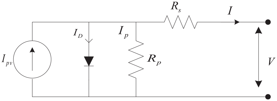
Illustration of a PV model with single diode.
The output current equation for the above model is determined based on the KCL equation (1)

From equation (1), the diode current is mentioned as the

where, α and Vt are the constants of a diode and the thermal voltage, that are further formulated in equation (3)

where, the Boltzmann constant is represented by


From equations (4) and (5), the open-circuit voltage is denoted as Vα and the input power ac of the solar system is denoted as Vinp. It is evident that, to model solar PV characteristics, it is necessary to compute five parameters (Othman et al., 2012). These values are distinguished using necessary partial shading conditions (PSC) steps that are further changed by launching Npp and Nss, then the customized formula is given as equation (6)

Here, the numbers of series-connected and parallel solar arrays are Nss, Npp. Then, the solar panel is examined with the number of PSC states, but the main ultimate of the suggested system aims in attaining maximum power under PSC form solar array. These analyses are depicted briefly in the following section. Before the analysis of the proposed method, the design strategy of the converters is considered. Here, different converters such as buck-boost converter boost and buck converter are utilized to analyze the PV system. Therefore, the detailed analysis of the above converter is described below.
Designs of DC-DC converters
The DC-DC converters are hardware circuits that are utilized to give a misfortune less transfer of vitality among various circuits at diverse DC voltage levels. Numerous DC-DC converters, named as the buck-boost converter, buck and boost converters, are employed in achieving maximum power from PV. Therefore, the detailed description of the converter is delineated in the following section.
Boost converter
In the DC-DC converter, boost converters are the most popular converters that venture up the voltage from its contribution to yield. The boost converter consists of energy storage inductor (L), a controlled switch (S) and a diode (D). At the output side, the load connects the filter capacitor (C) (Vinifa et al., 2017), as shown in Figure 2.
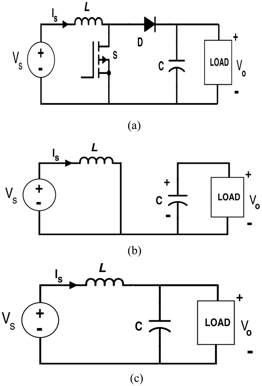
(a) Structure of boost converter and operations while (b) switch ON and (c) switch OFF.
Then, the output voltage (

where,
Buck converter
The converter that steps down its voltage is referred to as the buck converter and this converter helps in connecting the solar array to resistance load (RL) load via battery. The buck converter circuit is comprised of the capacitors, electronic switches, inductors and diodes (Boudaraia et al., 2017), which are shown in Figure 3.



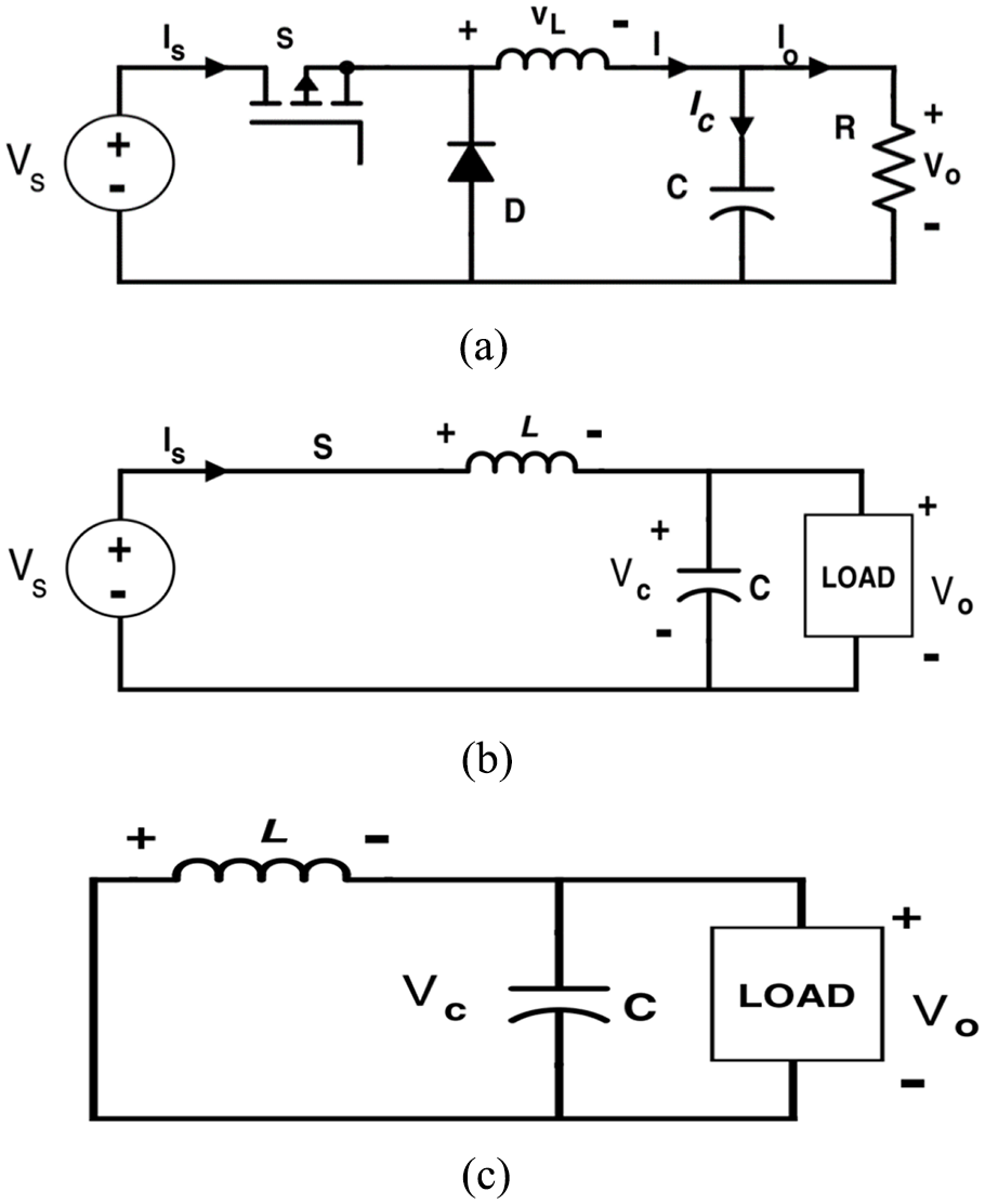
(a) Structure and working operation of buck converter, (b) mode -1 and (c) mode -2.
From the above figure, the duty cycle, input voltage, output voltage, switching frequency is represented by D,
Buck and boost converter
This section describes the buck-boost converter, commonly referred to as an inverting DC-DC converter. For example, the extremity of the yield voltage is turned around and is contrasted with the information supply. Subsequently, it is a negative-yield buck-boost converter. The tasks in accordance with the Buck-boost converter are as per the following: If the diode is reverse bias, then the transistor is in ON condition, therefore, the diode fails to conduct (Blange et al., 2015). During the interval,


The following equations determine the voltage across the inductor


As soon as the diode conducts, the transistor will be turned off and it should be at the particular interval

For a single switching cycle, the change in the inductor current reaches zero during the steady-state operation. Therefore

From the above equation, the converter’s duty cycle is denoted by

Based on the above equation, the switching time and the on-state time are denoted by

Based on the above equation, the output voltage equation for the boost, buck and the buck-boost converter of the PV is deliberated. The working operations of the converters are already described. Then, the FLC is modeled to obtain the maximum power of PV. Therefore, the detailed process of the proposed FLC is described in the section below.
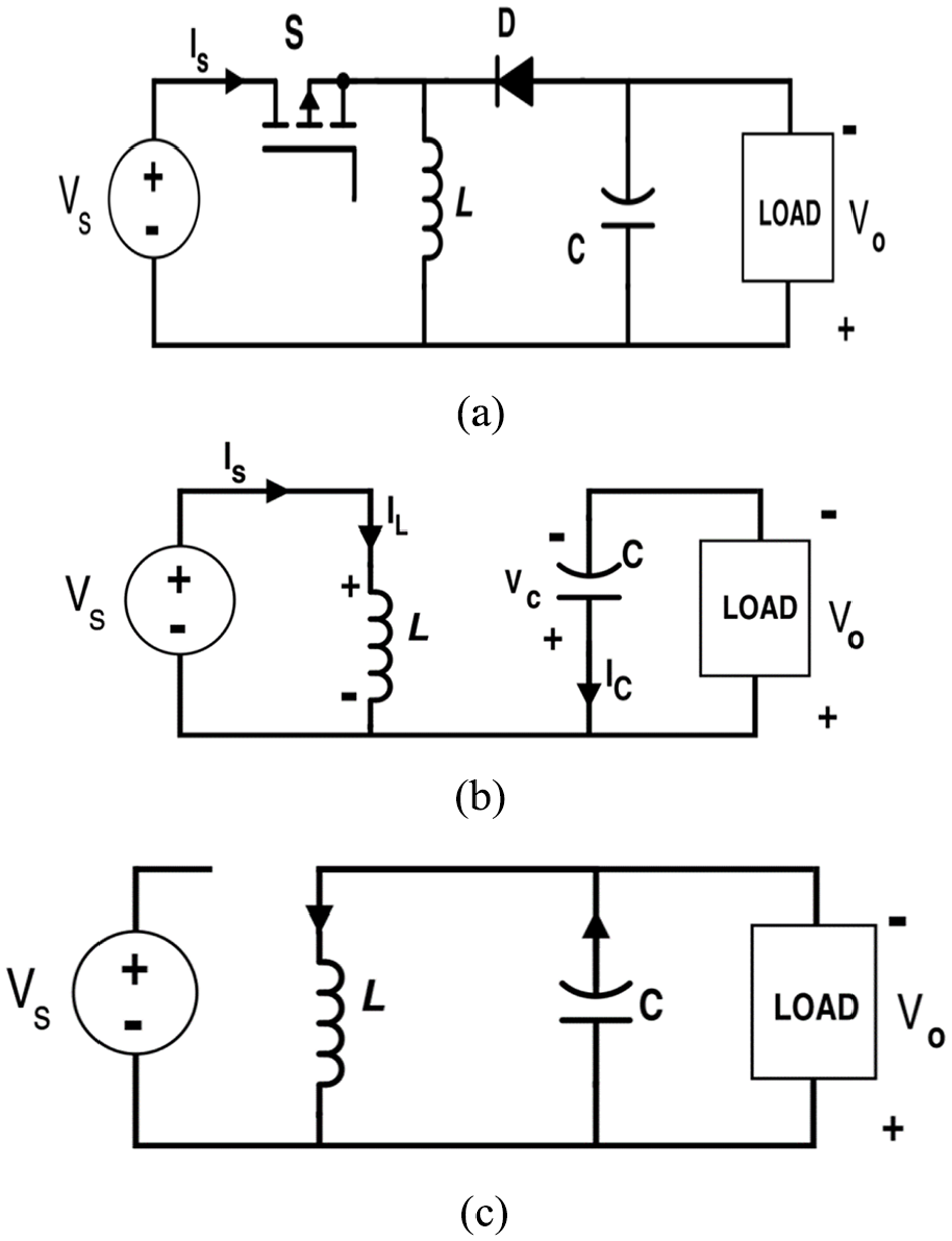
(a) Structure of a buck-boost converter and working operation, (b) ON and (c) OFF condition.
FLC-based boost converter for tracking MPPT
In this sub-area, the FLC-based boost converters are depicted in attaining the most extreme power of PV. In the previous section, the operations of the boost converters are already portrayed. Recently, one of the well-known techniques known as the FL control-based MPPT strategies is used for PV (Al-Majidi et al., 2018), due to its simplicity and imprecise inputs. With the utilization of FLC, the maximum power is obtained under varying climatic conditions. The duty cycle of the boost converter provides the output of FLC. By modifying the duty cycle of boost converter, the maximum power can be accomplished. The inverter is used in the conversion of DC/AC, which drives the load. The process flow for the proposed methodology is demonstrated in Figure 3. In the structure, the PV connects the boost converter with the load. Here,
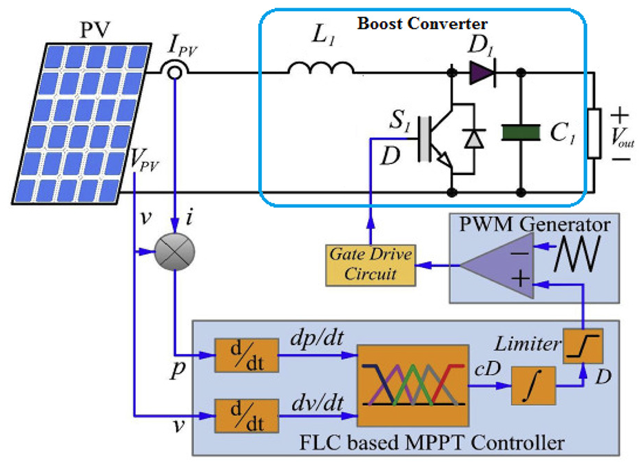
FLC-based boost converter for MPPT in PV system.
Here, the FLC is utilized in the tracking of maximum power from the solar PV panel. In this process, the FLC is worked under different conditions of constant irradiance and variant irradiance processes. In the normal irradiance analysis, the outputs are determined according to their inputs and the generalized rules. The generalized rules are applied to the various converters for analysis. Based on the generalized rules, the FLC is designed and the outputs are generated for the different patterns. The detailed explanation of the FLC is specified in the following section.
FLC in extracting the maximum power
Here, the FLC working procedures are mentioned with the following stages and the block diagram is shown in Figure 6.
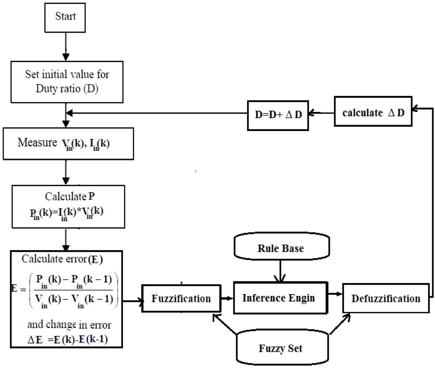
Structural diagram of fuzzy controller for MPPT.
Here, the error (e(k)) refers to the deviation in power



where Wi and Ci are the minimum numbers of membership functions and the mid-range of the output membership function. Crafted by the traditional FL-MPPT aims in providing the information where the esteem is more prominent compared with zero and the gradual difference in the duty cycle increments till the MPP of the duty cycle is under zero, at that point inverse happens till the ideal esteem is obtained. Then, the following information is utilized to decrease the duty cycle based on oscillation adequately.
The fuzzifier inputs are characterized into Gaussian membership functions that are further categorized into five different categories: positive-big (pb), negative-small (ns) positive small (ps) negative-big (nb) and zero (ZZ). The defuzzifier comprises of output duty cycle
Fuzzy rule generation for constant irradiance.

Thus, the FLC provides a boosted voltage output voo, thus extracting the maximum power. Additionally, the FLC tracks the maximum power and this output is sent as feedback to the boost converter followed by the beginning of the next processes. There occurs a rapid reduction in the output voltage of the ripple boost converter, that is, output voltage ripple is controlled and also results in the reduction of the settling time. The extracted voltage voo is, therefore, set to boost converter as a boosted voltage and is given to the inverter for the conversion of DC to AC to transmit the load for commercial use, economical use, and so forth.
The above fuzzy rules are generated for the constant irradiance conditions only. For the variation presented in the solar irradiance, it has been analyzed in two ways, like the irradiance in lower and higher cases. To determine this type of analysis, the following rules are generated and are further employed in extracting the maximum power from the PV array. Here, the conditions are applied to analyze the maximum power from PV, which is mentioned below.
The conditions for the δ(G) are analyzed in the following

Based on the above condition, the rules are generated under the positive and negative responses only, which are exactly mentioned as nb, ns, pb and ps. To analyze the performance of the duty cycle of the boost converter, the following equation is utilized

In general, the FLC based on MPPT is viewed as a standout amongst the most effective controller for a PV framework due to its high precision in achieving the optimal MPP. Moreover, as referenced prior, it does not need training data information and consequently takes a shot at various sorts of PV modules the equivalent MPPT structure. The input and outputs are classified into the following subsets: positive-big (pb), negative-small (ns) positive small (ps) negative-big (nb) and zero (ZZ). These above-mentioned subsets are tabulated in Table 2. The procedure is preceded until the ideal MPP is obtained and followed by the wavering of an ideal MPP. To stay away from the drift issue related to positive quick irradiance changes, the FLC guideline is altered in a reversed direction when (DP/P)>0.01, which is equivalent to the pb in the subsequent info (Yan et al., 2012). The output of the proposed system is the variable duty cycle. Finally, one important characteristic is noted, whenever the operating points are a long way from MPP, the step size of the duty cycle is huge. When it is tiny, the operational point surrounds it. Furthermore, the proposed framework gives less intricate usage, least handling time and more conveyance contrasted. The traditional FL-MPPT, as a result of its lesser number of FLC principles are established. Similarly, the other buck converter and the buck-boost converters were worked with the PV system. A similar way of analysis was presented in extracting the maximum power from the PV panel by employing FLC. Then the structure of buck converter with FLC and buck-boost FLC is determined and analyzed their corresponding results.
Fuzzy rule generation for irradiance variation.

Results and discussions
This section proposes an FLC-based buck-boost converter, boost converter and buck converter that are designed for analyzing the MPPT of a PV panel. The proposed technique is implemented with 4GB RAM, Intel(R) Core(TM) i5 processor under the platform of Simulink/MATLAB 7.10.0 (R2017a). The proposed framework based on the Simulink model is represented in Figure 7. The proposed approach is analyzed with the variant irradiance and constant irradiance, which enhances the power gathering capacity of the PV. From various PV irradiance conditions, the maximum power is extracted. The proposed approach utilizes current and voltage values based on information obtained from the PV. On such occasions, the systems reach end, and then the FLC turns out to be very much adapted to produce the ideal control beats of the converter. The execution of the proposed approach is described in the following segment.
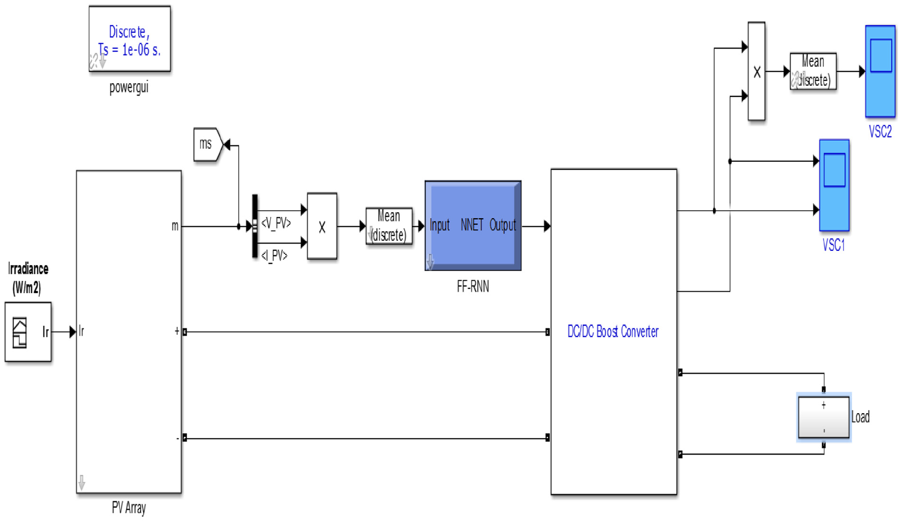
MATLAB/Simulink model of the proposed approach.
Here, the proposed framework is executed and assessed and the results are investigated under various irradiance changes of the heap associated with the solar array. Ordinarily, the energy obtained from the solar array is obtained followed by the MPPT method. The converter circuit utilizes the anticipated current and voltage control to obtain an ideal sinusoidal waveform. The execution of the proposed framework depends on the power parameters of the load associated with the solar module. In this procedure, the execution is assessed from the diverse shading sorts and irradiance. The sorts are given as:
Performance metrics
The performances of the proposed method and the ordinary strategies are measured; for the voltage, current and power.
Voltage:
The voltage or the electric potential difference is defined as the differences of the electric potential among two points. The unit of voltage is measured in volts and the symbol that signifies the voltage is V.
Current:
The rate of electric charge flows in a circuit is referred as current. The unit of electric current is measured in amps and I represent the symbol for current.
Power:
The total amount of energy converted or transferred per unit time period determines the power.
The distinctive sorts of investigations are executed in the following section.
Case 1: Performance analysis of the PV system with normal irradiances
This section describes the possible circumstances at different irradiance having the voltage; the powers and the current to examine the high power. At first, the current, voltage and power of the PV board depend on the traditional strategies that are portrayed in Figures 8(a), (b) and (c). The PV current takes 0.075 seconds at the 6A settling process, the voltage is 0.085 seconds at 125V settling time and power is settled as 750W.
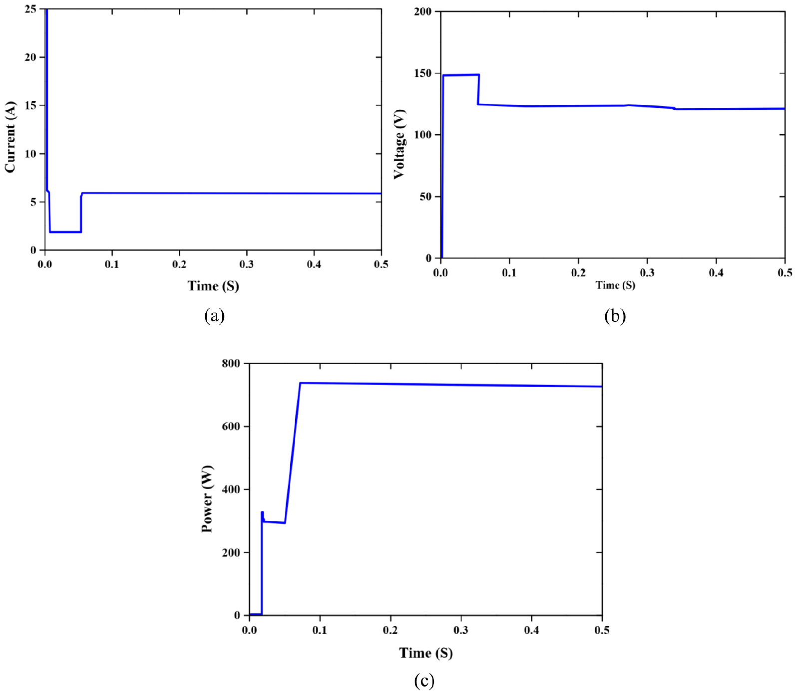
Performance analysis of PV (a) current (b) voltage and (c) power.
In Figure 9, the performance analysis of load voltage, power and current are illustrated. In light of this kind of illumination, the power is created consistently and this condition is not working in all circumstances. In this sort of condition, the irradiance is continually 1000 w/m2 and the power from the PV is changed because of the shading execution of the framework. For this investigation, the most extreme power was created and given to the load. At that point, the execution analysis of this approach is to check through another sort of shading condition is given beneath.
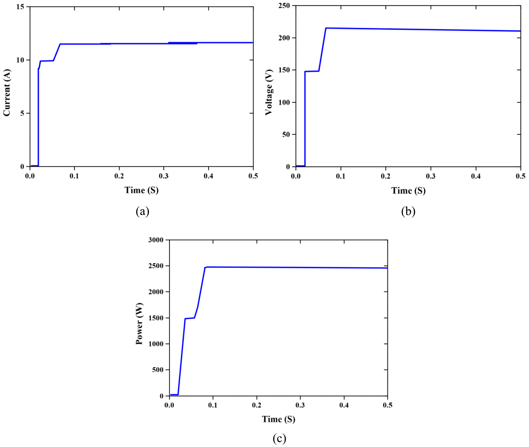
Performance analysis of (a) load current, (b) load voltage and (c) load power.
Case 2: Performance analysis of the PV System with some partial shading conditions
In this case, partial shading condition is performed based on the shading pattern, which is measured from the PV panel. The PV shading conditions and patterns are given in Table 1. Based on these shading patterns the performance analyzes three different conditions, which are evaluated in the following subsection.
Under various irradiance conditions, the shadow covers all the photodiodes and produce the power in light of the irradiance. The shading pattern is specified as (250, 900, 150). In this, the parameters control the light of the current procedures from breaking down the execution of the proposed strategy. The evaluated parameters are shown in Figure 10, which depicts the current system that uses irradiance and power from the PV.
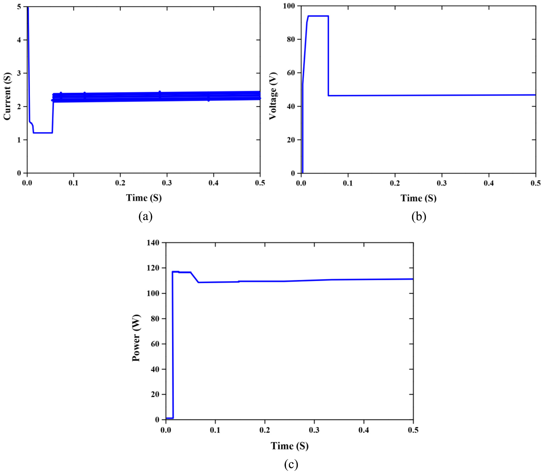
Performance analysis of PV (a) current (b) voltage and (c) power using proposed technique.
For breaking down, the execution load current, voltage and the power of the proposed system in sort 4 are displayed in Figure 11, which contains the evaluated parameters of the proposed method. The load power is 490W at 0.85 seconds settled process and voltage is 81V at 0.1 seconds settling process. Therefore, the examination investigation is performed in the accompanying section.
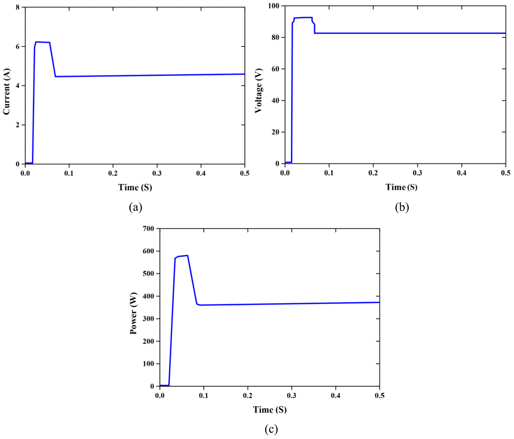
Performance analysis of load (a) current (b) voltage and (c) power using proposed technique.
Comparison analysis with boost, buck converter and buck-boost converter
This section provides the correlation examination that relies upon the normal and various conditions of irradiance and is analyzed with boost, buck and buck-boost converter with proposed FLC. Then, the examination investigation of the mentioned framework is analyzed and illustrated in Figure 12. From the correlation examination, the proposed procedure is accumulated to obtain the most extreme power in various types for 1.5 seconds relating the voltage and power.
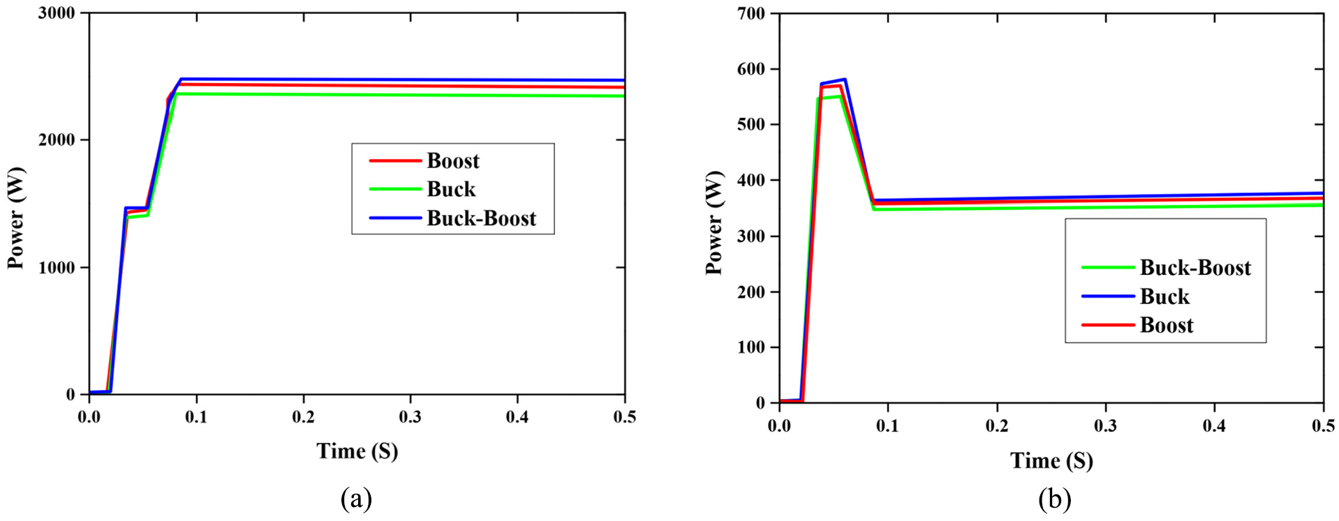
The comparison performance of power output of different methods in (a) stable irradiance, (b) irradiance changes.
Comparison of FLC controller over other controllers
To make a further comparison, the performances of the proposed FLC controller are evaluated with three other controllers: PI (Patel et al., 2014), PID and PD (Bejarbaneh et al., 2019) controllers. Therefore, the comparative graphical analysis for various controllers is mentioned in Figure 13. It is noted that the proposed FLC controller provides better performances when compared with all controllers.
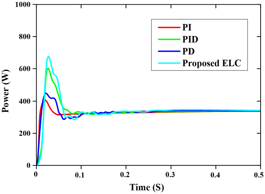
Comparative graph of FLC controller over other controllers.
Conclusion
This paper presents the FLC with buck, boost and buck-boost converter for MPPT of a PV panel. The proposed strategies were actualized in the Simulink/ MATLAB platform and are examined with various converters. Due to the environmental changes, the current and the voltage characteristics of a PV are analyzed with the help of the proposed strategy. To decrease the system payback period and to increase the efficiency, the PV panels should be operated in MPPT. The PV panels at the maximum power point under variable and normal irradiance conditions to enhance the power thereby providing an appropriate current and voltage is the major role of this research work. The proposed FLC-based buck-boost converter is deliberated and analyzed with other converters like buck converter and boost converter. The performance strategies of the converters are analyzed to provide maximum power from the PV. At this point, the control procedures were proposed to manage and resolve the system-level function difficulty. In this proposed controller execution, the proposed controller was exploited to develop the expand limitation of the converter and develop the power eminence of the PV. The objective function was defined and specified their constraints also the performance index was analyzed for achieving the optimal results. The proposed controller was exploited to discover the finest pulses for improving the presentation of the system. Variable ecological conditions cause a change in current, voltage and, furthermore, a variation in the greatest accessible intensity of PV. The simulation result is provided to obtain the efficiency of the converter. Therefore, to prove the efficiency, the performances are analyzed and compared with the boost and buck converter respectively. Moreover, the efficiency of the converter also analyzed for getting the optimal operation of a DC-DC converter. The proposed methodology of the converters is broken down and gives the most extreme power from the PV.
Footnotes
Declaration of conflicting interests
The author(s) declared no potential conflicts of interest with respect to the research, authorship, and/or publication of this article.
Funding
The author(s) received no financial support for the research, authorship, and/or publication of this article.
