
Abstract
Rolling bearing local fault vibration mechanism research is the theoretical basis of advanced bearing fault diagnosis and size measurement technology. In this paper, the additional displacement and impact force excitation of inner and outer ring local faults under low speed and heavy load condition are analysed, and rolling bearing local fault vibration model is established. The simulated dual impulse characteristics have higher accuracy under low speed and heavy load condition compared with other traditional local fault models. The outer and inner ring fault simulated dual impulse interval errors are 6.7% and 1.1%, respectively. Then the local fault vibration mechanism is analysed, and the influence of heavy load condition on dual impulse characteristic is not negligible. Finally, a size measurement method of bearing local fault based on vibration model is proposed. Two sizes of outer ring fault bearing are tested in four different working conditions, and the average measurement error is 3.78%. The results show that the proposed method can overcome the influence of different working conditions and accurately measure different local fault sizes.
Keywords
Introduction
As an important part of rotating machinery, rolling bearing is widely used in various industries, and bearing fault diagnosis technology has become a significant guarantee of equipment safe operation (Cui et al., 2019; Li et al., 2019). Although bearing failure causes and final failure forms are various, most of them are developed from the early local defects. When rollers or raceway touches local fault, the fault pulse amplitude modulation is carried out with the system natural frequency as the carrier, so that vibration signal contains bearing fault information (Glowacz et al., 2018). However, the vibration response process of rolling bearing is complex, and simulation signal based on simple mathematical method cannot reflect actual phenomenon. In addition, the equipment working conditions of mining, construction machinery and similar fields are poor, and the excitation principle is special compared with a conventional situation (Chen et al., 2019). Therefore, the research on vibration mechanism of bearing local fault under low speed and heavy load condition is the theoretical basis for further improving fault diagnosis and life prediction technology level of rolling bearings in related fields.
In view of the vibration characteristics analysis of rolling bearing, researchers have already made many achievements (Cao et al., 2018; Singh et al., 2015; Xu et al., 2019). Sassi et al. (2007) gave the calculation formulae of impact force between roller and bearing defect. By modelling bearing fault vibration as a function of bearing internal structure, movement, load and transfer path between sensors, the simulation results similar to signal collected by sensors were provided. Liu and Shao (2017) established a rigid rotor bearing system dynamic model for bearing local defects, and derived a new method for additional deformation of sharp edge. The finite element dynamic model of a bearing pedestal system with local fault was also established to study the vibration characteristics induced by faults with different sizes (Liu et al., 2019). Wang et al. (2020) analysed the surface composite fault excitation mechanism of deep groove ball bearing under different working conditions.
To realize fault diagnosis of rotating machinery including rolling bearing, many methods have been proposed (Li et al., 2020; Liu et al., 2014). These methods can achieve good diagnosis results, and one of the key points is the effectively extraction of fault feature components and information (Guo et al. 2019; Huang et al., 2020). However, many of them are not designed to measure fault degree. For this purpose, the detailed signal feature directly related to fault size needs to be studied and utilized. Some studies show that the contact process between roller and local fault is not a single event (Niu et al., 2020; Sawalhi and Randall, 2011). Ahmadi et al. (2015) proposed an improved nonlinear dynamic model for contact force and vibration response of rolling bearings, which could provide more accurate prediction results for low-frequency response of roller entering fault. Luo et al. (2018, 2019a) established the dynamic model of ball bearing with inner ring fault aiming at dual impulse characteristic; the experiment showed that the model can provide accurate simulation results. Many researchers began to use dual impulse characteristic to estimate bearing fault size (Kogan et al., 2018; Moustafa et al., 2016). Bastami and Vahid (2020) used autoregressive model and envelope analysis to enhance signal characteristics, and estimated the size of natural defects of tapered roller bearings under different speed and load conditions. Chen and Kurfess (2018, 2019) established a new defect size estimation model of rolling bearings, which was combined with VMD Variational mode decomposition to remove high-frequency noise and help to identify the entry point. The method was verified on CNC machine tool. Luo et al. (2019b) proposed an analytical model for estimating the spalling size, and the results were in good agreement with the actual spalling size.
According to the above, the existing rolling bearing vibration mechanism and fault size measurement research is mostly aimed at common working conditions, and the influence of low speed and heavy load is ignored. In addition, the accurate models are usually only used for characteristic analysis rather than directly supporting measurement work. In this paper, the time-varying displacement and impact force are considered simultaneously, and the excitation mechanism of rolling bearing local fault is studied. Based on Hertz contact theory, the contact stiffness of each roller is calculated, and the vibration model of rolling bearing with local fault is established. The model validity is verified and the local fault influence on bearing vibration response under low speed and heavy load condition is analysed. Furthermore, a size measurement method of rolling bearing local fault based on vibration model is proposed. The dual impulse characteristic in bearing vibration signal is used to measure local fault size, and the interference of different load and speed on measurement accuracy can be overcome. The proposed method uses the verified simulation model to transfer most workload to prior preparation stage. The computation of actual measurement stage is reduced significantly, which will help to realize online measurement. The research results provide a theoretical basis for accurate diagnosis and deep analysis of rolling bearing local fault.
Rolling bearing local fault vibration model
Model simplification
In order to study the local fault influence on dynamic characteristics of rolling bearings, it is necessary to build a rolling bearing dynamic model. Considering the accuracy and calculation efficiency, the following assumptions are made: (1) both inner and outer ring of bearing are rigid and are installed on rotor and bearing seat respectively with interference fit; (2) roller sliding, mass, inertia force and cage are ignored, and the contact with inner and outer rings meets Hertz contact theory; (3) axial bearing structure and loads are ignored. As a result, rolling bearing structure can be shown as Figure 1(a). Rollers are simplified as springs and damping, and the simplified bearing dynamic model can be established as Figure 1(b).
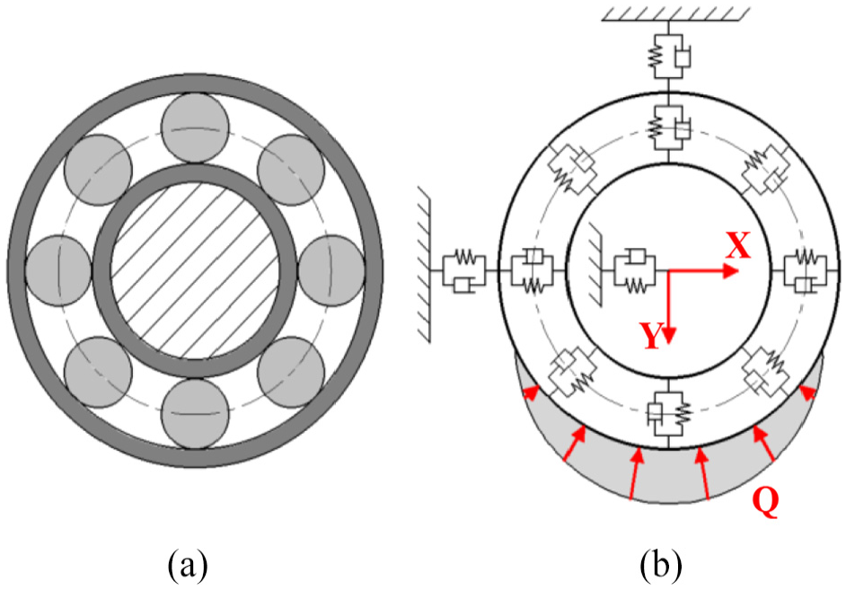
Rolling bearing structure and simplified dynamic model.
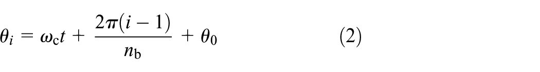
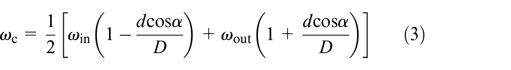
Local fault excitation
Under the action of radial load, the inner and outer ring axes have relative displacement. Some rollers are compressed and form support force. Therefore, the radial deformation of ith roller can be expressed as follows:

where
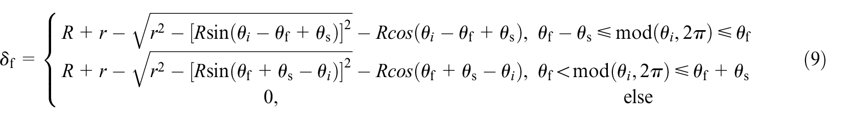
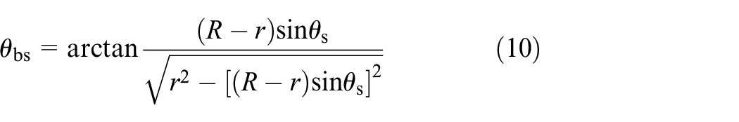
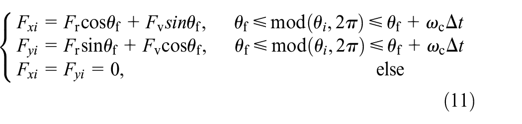
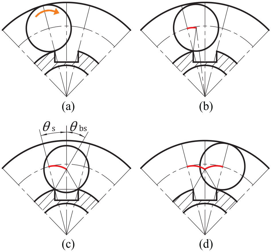
The additional displacement generated by local defects excites the system and makes bearing vibration signal carry pulse components. As shown in Figure 2, the additional displacement path cause by the outer ring fault can be divided into two stages. First, the roller continues to move after contacting with the local fault, and its centre makes the first stage circular motion around the fault front edge. For a small size fault, the roller will not touch the bottom. When the roller contacts with the fault front and back edges at the same time, the additional displacement
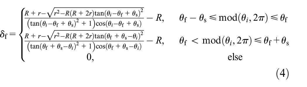
where R and r are radii of pitch circle and roller respectively,


where
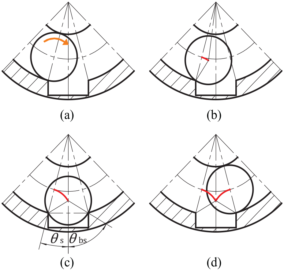
Additional displacement path of outer ring local fault.
Similarly, the additional displacement path of the inner ring local fault is shown in Figure 3. Different from the outer ring fault, the touching speed between roller and inner ring fault is the relative speed of roller revolution and inner ring rotation, and the fault location changes with rotor rotation. The additional displacement of the inner ring fault can be calculated as follows:
where the fault centre phase
According to
Finally, the excitation model of additional displacement and impact force caused by local fault is established.
Additional displacement path of inner ring local fault.
Roller support force
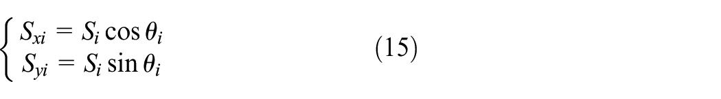
In order to calculate bearing internal interaction force, the single roller contact stiffness should be calculated first. Based on Hertz contact theory, the single roller support force
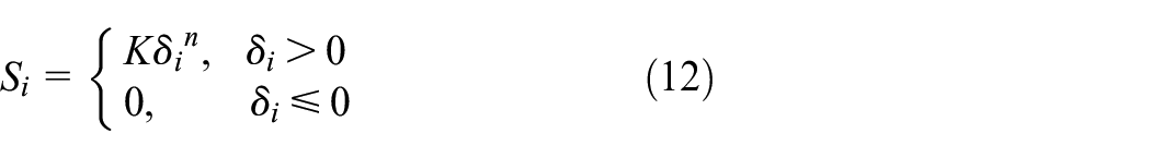

where n is the deformation index, for ball bearings n=1.5 and for cylindrical roller bearings n=10/9. Here

where l is roller length. By calculating single roller contact stiffness, radial deformation, local fault additional displacement and impact force, the total roller support force to inner and outer rings in x and y directions can be calculated as follows:
Rolling bearing dynamic model
Based on the above derivation, the rolling bearing dynamic differential equation can be obtained as follows:
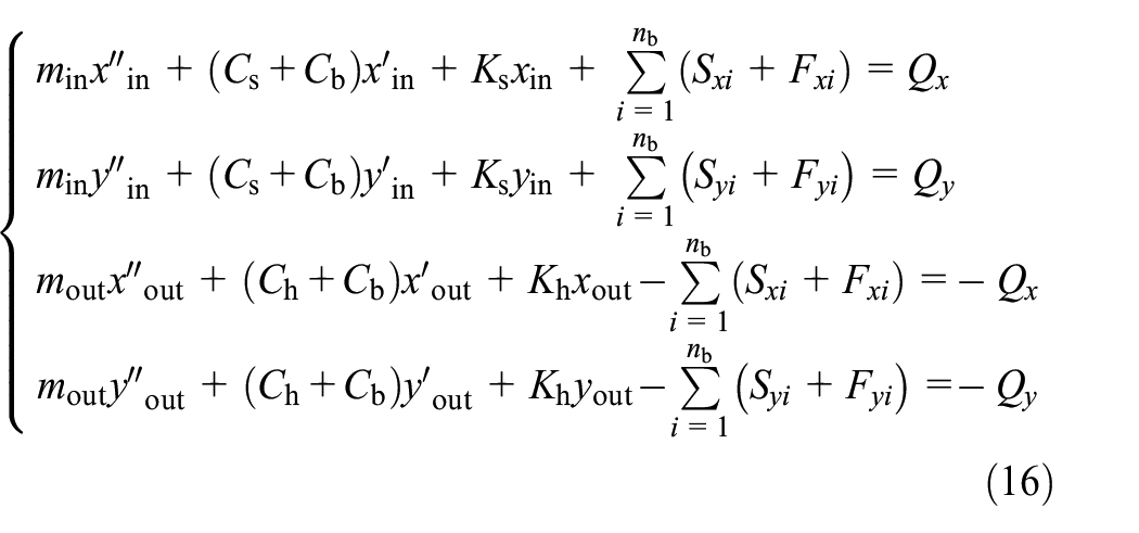
where
Model-based size measurement method of bearing local fault
The impact components in bearing vibration signal contain dual impulse characteristics directly related to the fault size. It can be used to measure fault size, but the influence of speed and load must be overcome first. The relationship between signal characteristics and operating parameters is very complex. Fortunately, the verified vibration model can theoretically provide high-precision simulation results as a reference. Therefore, a measurement method of bearing local fault size based on vibration model is proposed. The method process is shown in Figure 4, and its specific steps are as follows.
Step 1: Establish local fault vibration model according to bearing parameters.
Step 2: Set benchmark conditions, including fault type f, reference fault size
Step 3: Collect bearing vibration signal, actual speed
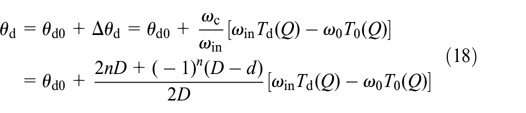
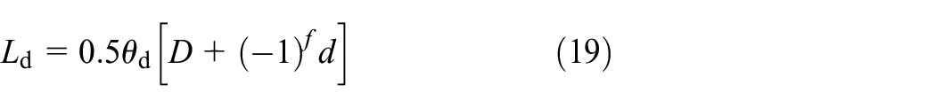
Step 4: Calculate the actual fault size
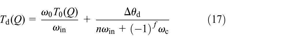
where
In this way, the local fault size of rolling bearing can be measured under different speed and load conditions. In actual measurement, steps 1 and 2 can be calculated and prepared in advance as prior knowledge, and the calculation cost of steps 3 and 4 can be greatly reduced. This is helpful to realize online measurement.
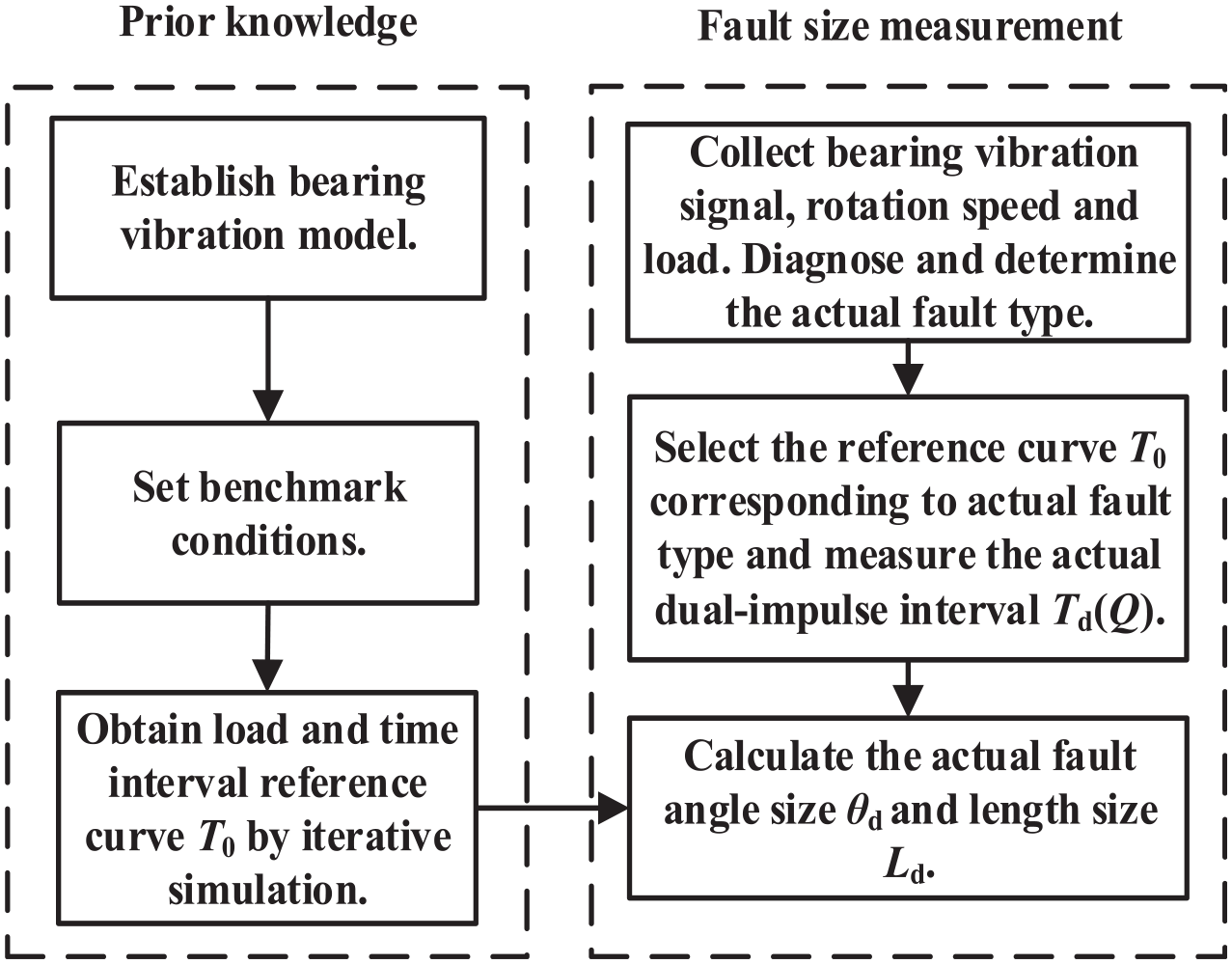
Process of fault size measurement method.
Model simulation analysis
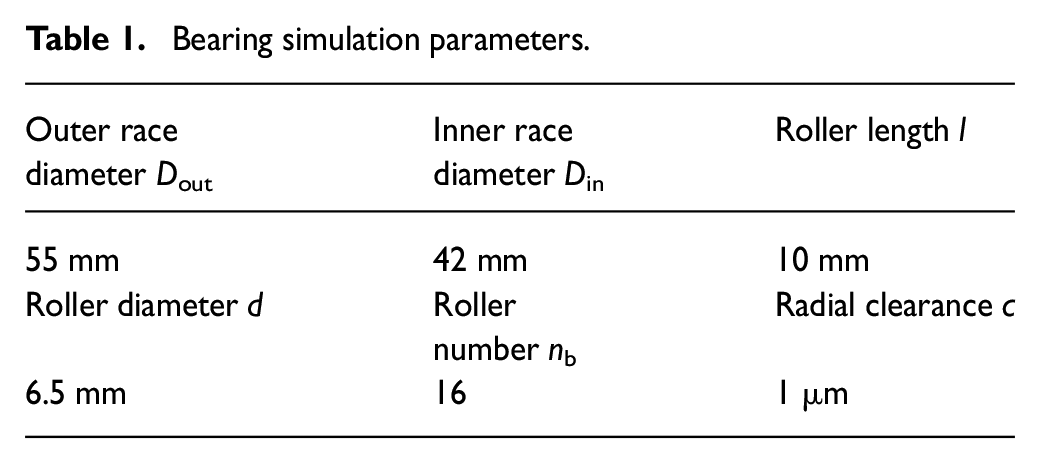
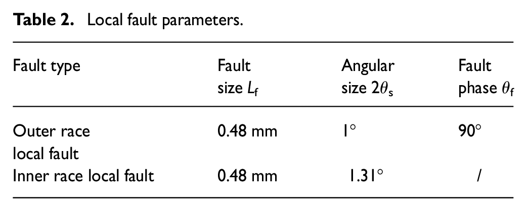
Taking cylindrical roller bearing NU1007 as the research object, its main structural parameters are listed in Table 1. The Runge–Kutta method is used to solve the bearing dynamic differential equations in equation (16). Time step is 10−5 s, simulation duration is 1 s, rotation speed is 4 Hz, bearing radial loads are Qx = 0 N and Qy = 1000 N, equivalent mass of inner ring with rotor and outer ring with bearing seat are 0.3 kg and 6 kg, respectively, roller contact stiffness is K=2.89 × 10⁵ N/mm, rotor stiffness is Ks=1000 N/mm, bearing seat stiffness is Kh=2×10⁶ N/mm, and dampings Ch, Cs and Cb are 2 Ns/m. The simulation local fault parameters are set as listed in Table 2 according to the actual test bearings. Considering bearing load, structure and general sensor arrangement, the acceleration simulation signals of outer ring and bearing seat in Y direction are selected for analysis. The simulation results are displayed in Figure 5.
Bearing simulation parameters.
Local fault parameters.
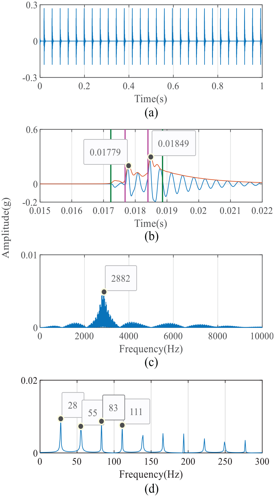
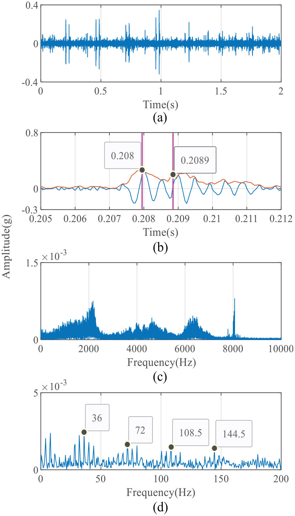
Simulation results of outer ring fault bearing: (a) simulation signal; (b) fault pulse; (c) frequency spectrum; (d) envelope spectrum.
As shown in Figure 5, the simulation time domain waveform of outer ring fault has some obvious impact characteristics. The single pulse envelope has dual impulse characteristic, the time interval of which is 7 × 10⁻⁴ s. The single fault pulse can be divided into three stages: initial fluctuation stage, dual impulse stage and vibration attenuation stage. The four time points dividing these three stages correspond to four roller events, that is, enter fault, lose compression, regain compression and leave fault, and are represented with four vertical lines in figures. The frequency spectrum shows that vibration is mainly distributed around 2800 Hz, accompanied by side frequency characteristics. The envelope spectrum shows that some peaks appear near the theoretical fault characteristic frequency of 27.71 Hz and its harmonic frequencies. They decay with order increase, which is consistent with the characteristics of fault periodic modulation.
The simulation results of inner ring fault are shown in Figure 6, and have obvious rotor speed modulation characteristic. In addition, the other time frequency characteristics are similar to the outer ring fault simulation signal. The dual impulse time interval is 9.1 × 10⁻⁴ s, and some peaks also appear in the envelope spectrum near the theoretical fault characteristic frequency of 36.29 Hz and its harmonic frequency.
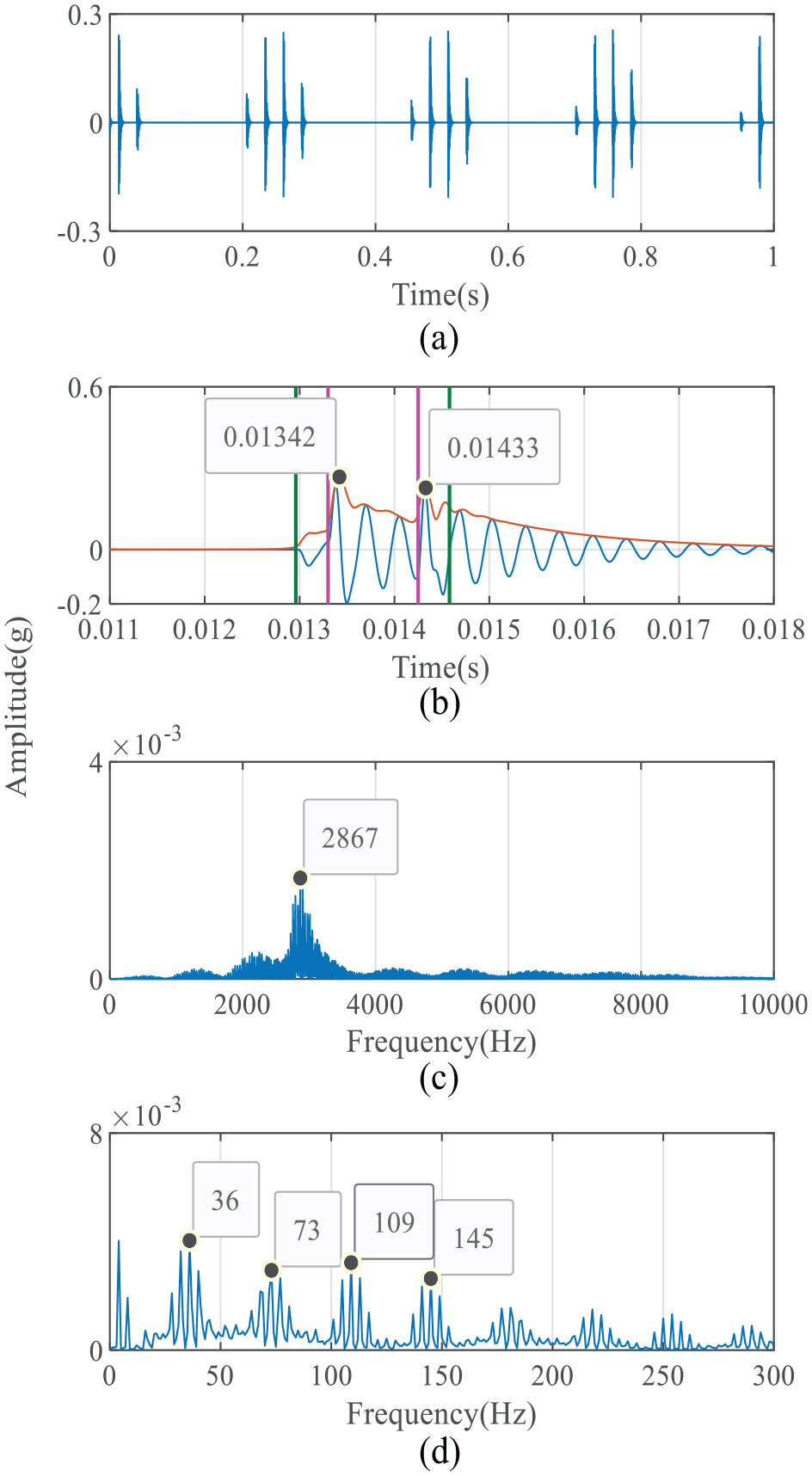
Simulation results of inner ring fault bearing: (a) simulation signal; (b) fault pulse; (c) frequency spectrum; (d) envelope spectrum.
Experimental verification
Model verification
In order to verify model effectiveness, the vibration signal acquisition experiment was carried out on the established bearing fault simulation device, and the inner and outer ring fault bearings were tested. The experimental device is displayed in Figure 7. The arrangement of test points and triaxial vibration acceleration sensors is shown in Figure 8. The test bearings shown in Figure 9 were installed on the right bearing seat in turn. The rotating speed and radial load were set as 4 Hz and 1000 N, respectively. The actual bearing and local fault parameters are the same as simulation settings in Tables 1 and 2. According to the acquisition result, the Z-axis signal was selected for analysis. The sampling frequency is 20 kHz and the experimental results are shown in Figures 10 and 11.
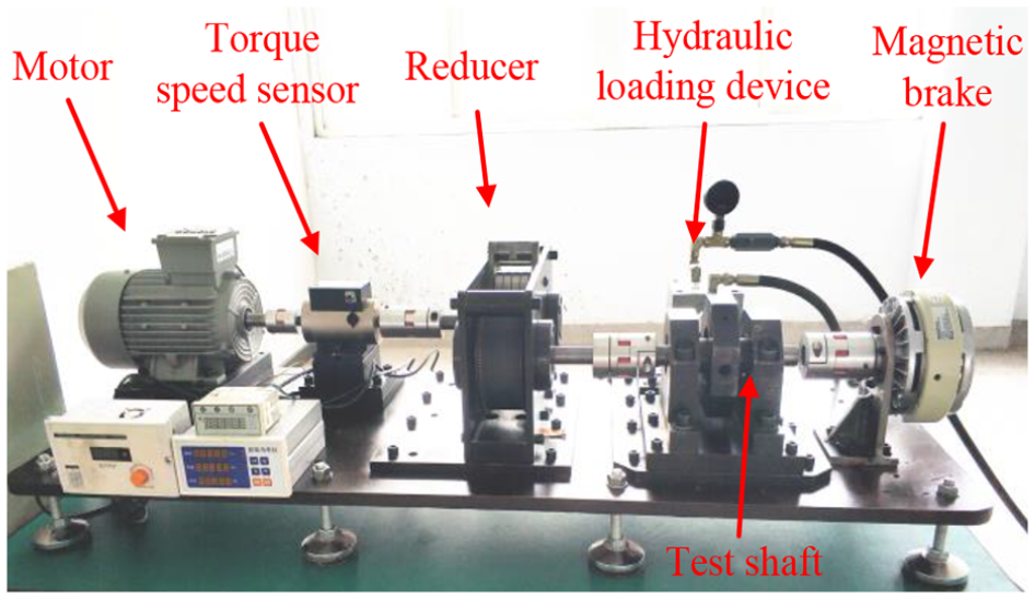
Signal acquisition experimental device.
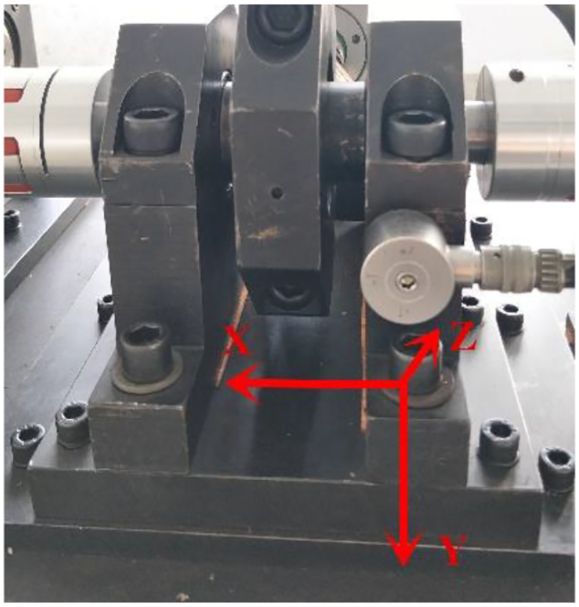
Arrangement of test points and vibration acceleration sensors.
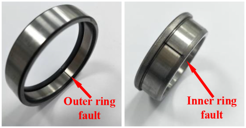
Test bearings.
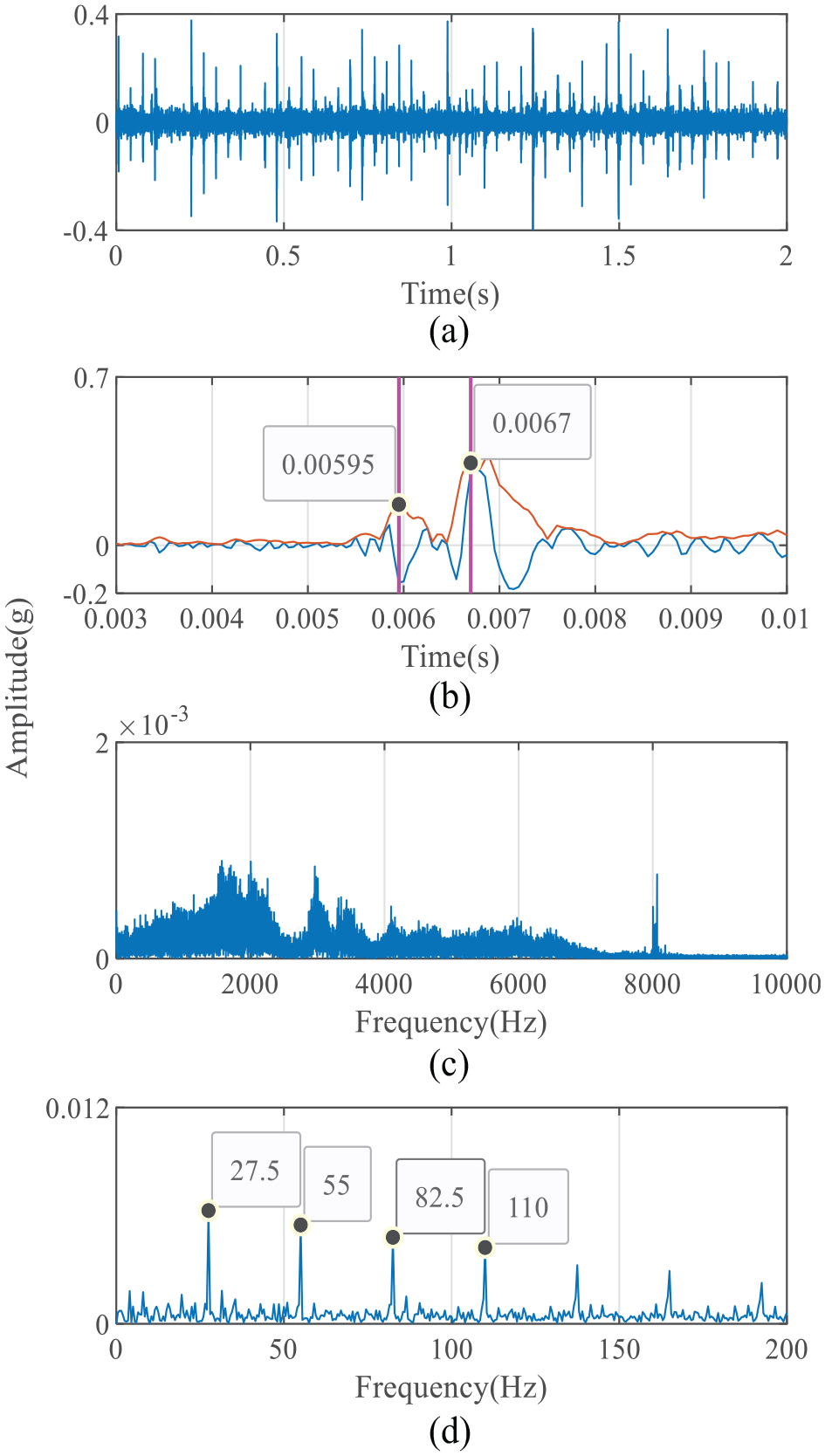
Experimental results of outer ring fault bearing: (a) experimental signal; (b) fault pulse; (c) frequency spectrum; (d) envelope spectrum.
Experimental results of inner ring fault bearing: (a) experimental signal; (b) fault pulse; (c) frequency spectrum; (d) envelope spectrum.
The comparison results show that the time domain waveform, shock details, spectrum and envelope spectrum characteristics of simulation signals and experimental signals are similar. Owing to noise and other interferences, the experimental signals have more complex spectrum components. Although their spectrum characteristics are different from those of simulation signals, they are similarly located in the high-frequency band. The envelope spectrums of simulation and experimental signals both have corresponding peaks at fault characteristic frequency position, and their peak attenuation trend and speed modulation characteristics are basically same. The actual characteristic frequency of outer ring fault is 27.5 Hz and that of inner ring fault is 36 Hz. The simulation error is 0.76% and 0.81%, respectively. In addition, comparing the fault pulses in simulation and experimental signals, it can be seen that they both have dual impulse characteristic. For outer ring fault, the experimental dual impulse time interval is 7.5 × 10⁻⁴ s, whereas simulation error is 6.7%. For inner ring fault, the experimental dual impulse time interval is 9 × 10⁻⁴ s whereas simulation error is 1.1%. From the above comparison, it can be seen that the main overall and detailed time frequency characteristics of model simulation and experimental acquisition signals are corresponding. Owing to the complex equipment structure and transmission path, there are some deviations in amplitude and system natural frequency, which is acceptable.
In order to further verify model effectiveness, the commonly used half sine function and step function are selected to simulate outer ring local fault with same size and working conditions for comparison. The simulation fault pulse is shown in Figure 12. The dual impulse time interval of half sine function is 1.41 × 10⁻³ s with 88%, error and the corresponding outer ring arc length is 0.421 mm. The dual impulse time interval of step function is 1.59 × 10⁻³ s with 112% error and the corresponding outer ring arc length is 0.475 mm. The bearing support stiffness changes instantaneously, and the simulation dual impulse time interval does not change with load. This means the two traditional local fault modelling functions are inconsistent with experimental signals under low speed and heavy load condition. Therefore, the effectiveness of established rolling bearing local fault vibration model can be proved.
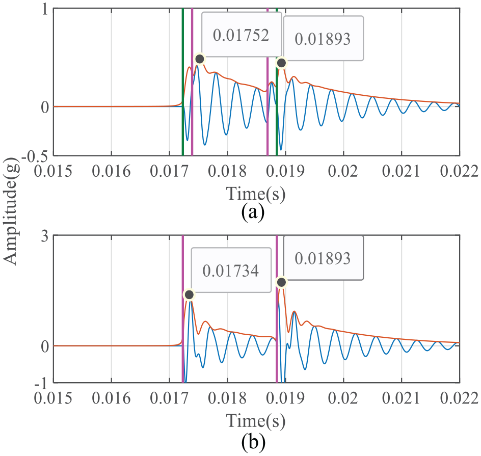
Comparison of local fault pulse simulation: (a) half sine function; (b) step function.
Vibration mechanism analysis
In this section, the vibration mechanism of local fault bearing is analysed based on the established model. First, set radial load and rotation speed as 10 N and 1 Hz, and the simulation results are shown in Figure 13. In the middle of dual impulse characteristic, a weak pulse corresponding to the time point that the roller impacts fault back edge appears. However, this feature cannot be clearly found in simulation and experimental signals. Therefore, it seems that theoretical impact force excitation can be ignored for tiny local fault under low speed and heavy load conditions.
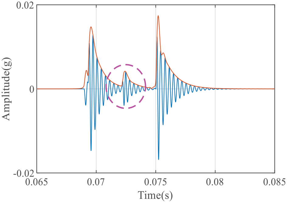
Vibration response of outer ring fault impact force under light load.
Second, the experimental results show that the radial load influence on dual impulse time interval cannot be ignored. Taking the 0.48 mm outer ring local fault as an example, the actual dual impulse time interval in Figure 10 is 7.5 × 10⁻⁴ s. According to roller revolution speed (i.e. cage rotation speed), the corresponding outer raceway arc length can be calculated as 0.224 mm, which has 53.24% error with the actual fault size. Using the established vibration model for analysis, Figure 14 shows the variation trend of outer ring fault simulation dual impulse interval with load when rotating speed is 4 Hz. When the radial load is 10 N, 1000 N and 2000 N, respectively, the time interval is 1.42 × 10⁻³ s, 7 × 10⁻⁴ s and 4 × 10⁻⁴ s, respectively. The corresponding outer raceway arc length is 0.42 mm, 0.21 mm and 0.12 mm, and the size estimation error is 12.9%, 57.1% and 75.5%, respectively. The variation range is large enough, and the error of directly using calculated arc length to estimate fault size also increases with load. In Figures 2 and 3, the fault additional displacement locus of roller is composed of two arcs, and its radial compression change process is not an abrupt change. The influence of this change trend is not obvious under high speed, light load or large size fault condition. However, the roller compression will increase significantly under heavy load condition. The longer compression gain and loss process will shorten the dual impulse time interval, and the small size of early fault can also make it more obvious.
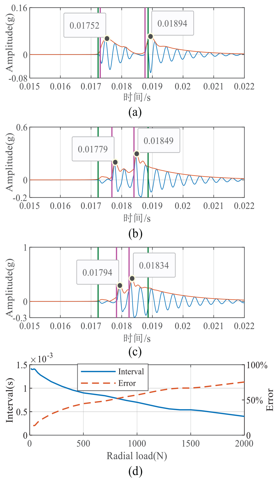
Dual impulse interval variation of outer ring fault bearing with 4 Hz speed: (a) 10 N; (b) 1000 N; (c) 2000 N; (d) interval and error trend.
Method validation
According to the above analysis, the heavy load influence should be considered while using dual impulse interval to measure fault size. Figure 14(d) shows that dual impulse interval is a function of radial load Q when local fault size
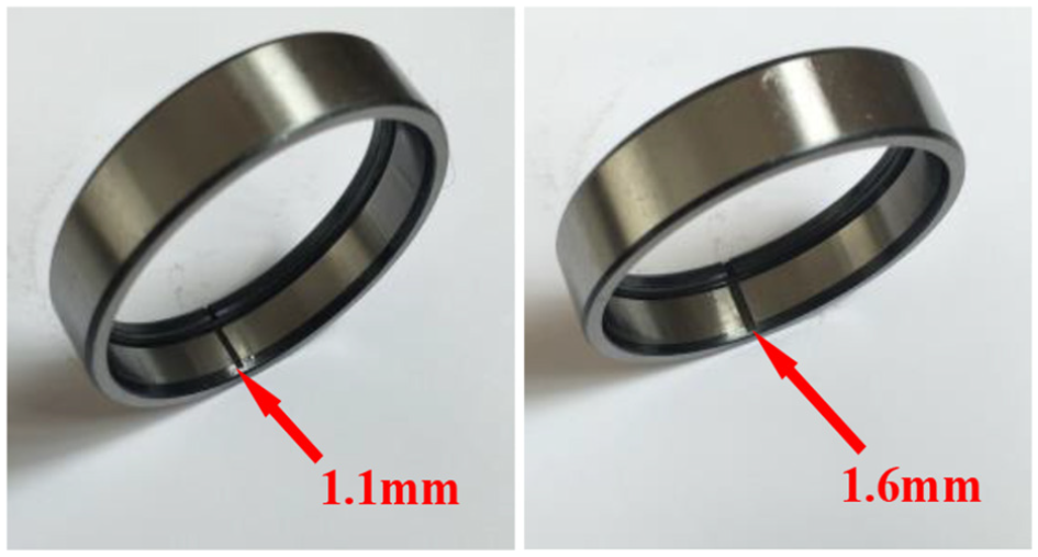
Test bearings with different size outer ring fault.
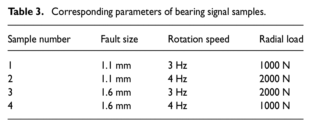
Corresponding parameters of bearing signal samples.
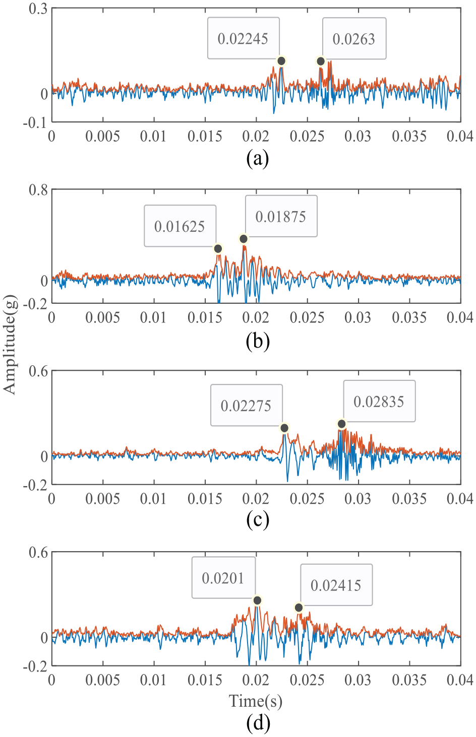
Actual dual impulse time intervals under different fault sizes and working conditions: (a) sample 1; (b) sample 2; (c) sample 3; (d) sample 4.
Experimental results of fault size measurement.
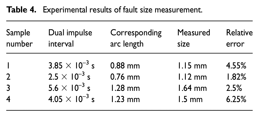
It can be seen that all measurement errors of different samples are small. They are 4.55%, 1.82%, 2.5% and 6.25% respectively, and the average error is 3.78%. The corresponding raceway arc lengths of measured dual impulse time intervals are far less than the actual fault sizes, which further prove that heavy load influence must be considered. Therefore, the proposed measurement method can effectively overcome its influence and provide accurate measurement results. In addition, the analysis results show that a single fault pulse still contains rich fault information and detailed features, and the relevant methods are worthy of further study.
To further show the work significance in this paper, the characteristics of the proposed method and its differences from previous works are compared and analysed. The characteristics of these methods are listed in Table 5. Two kinds of simplified rolling bearing dynamic models were respectively established in Sassi et al. (2007) and Luo et al. (2018). Most of the works represented by model 1 only consider the influence of speed, load and other factors on the overall time-frequency characteristics of simulation signals. The simulation results of model 2 contain dual impulse characteristics, but the influences of roller motion path and load are not considered. The above works are only used to provide the simulation vibration signals of fault bearings and study their vibration characteristics. In (Luo et al., 2019b), the roller motion path was studied, and the relation of dual impulse time interval and fault size was derived according to the geometric relationship of bearing structure. The established equation contains the load factor in theory. However, the derivation and calculation are complex, and some preconditions such as roller compression are obtained under the static assumption. In addition, the maximum relative error of experimental results with different speeds is less than 6.70%, but the load influence was not analysed and discussed.
Comparison with previous works.
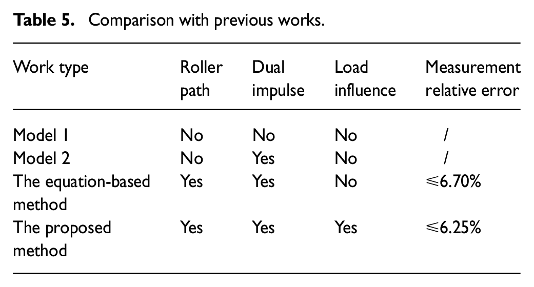
In this paper, the proposed method considers the influence of load, and the measurement results can maintain high accuracy under different working conditions. The simulation results of validated effective model are used to measure the actual fault size. Compared with the previous work based on geometric relationship and formula derivation, the mathematical model of size measurement part can be greatly simplified, and the application scope of simplified bearing dynamic model is expanded. According to this idea, it is easy to apply the proposed method to other bearings with same type. The model simulation results can be calibrated repeatedly according to a small amount of experimental data. After that, the proposed method can maintain good measurement accuracy in any other working conditions, especially for faults with small size, for which the proportion of load effect cannot be ignored. Therefore, the effectiveness and advantages of the proposed model-based fault size measurement method can be verified.
Conclusions
In this paper, the time-varying displacement and impact force excitation caused by bearing inner and outer ring local faults have been analysed. Considering roller motion trajectory, the bearing local fault vibration model has been established. The dual impulse time interval error between model simulation signal and experimental collection signal is 6.7% in the case of outer ring fault and 1.1% in the case of inner ring fault. Combined with simulation and experimental results, the vibration characteristics of local fault bearing under low speed and heavy load condition have been further discussed. The results show that load influence on dual impulse time interval cannot be ignored. Based on the established vibration model, a bearing local fault size measurement method has been further proposed. Two kinds of outer ring fault bearing were used to verify the method under four different working conditions, and experimental results show that the average measurement error of local fault size is 3.78%. The proposed method can overcome the influence of different speed and load changes, and the calculation in actual measurement stage is relatively simple. In addition, the research results provide some theoretical basis for fault diagnosis and life prediction technology development of rolling bearing in low speed and heavy load condition based on vibration signal.
Footnotes
Appendix
Declaration of conflicting interests
The author(s) declared no potential conflicts of interest with respect to the research, authorship, and/or publication of this article.
Funding
The author(s) disclosed receipt of the following financial support for the research, authorship, and/or publication of this article: This research was funded by the National Natural Science Foundation of China (grant number 51905147), the Natural Science Foundation of Jiangsu Province (grant number SBK2020022062) and a project funded by the Priority Academic Program Development of Jiangsu Higher Education Institutions.