






Abstract
The response-based design approach is a straightforward method for proportional–integral–derivative (PID) controller tuning. In this method, an open-loop process response is used to tune the PID controller for fixed robustness. In this article, new response-based PID tuning rules are proposed with adjustable robustness and response. Instead of three PID variables, the proposed PID tuning method allows the user to adjust the process response with a single variable
Introduction
The simple structure, easy implementation, and satisfactory closed-loop performance of the proportional–integral–derivative (PID) controller make it the most extensively used controller in the industrial process. The proportional gain
In the response-based tuning technique, the PID controller’s parameters are tuned based on the processes’ transient response. The response-based PID tuning approach was proposed by Ziegler and Nichols (1942). The Ziegler–Nichols (Z-N) open-loop PID tuning control method, also known as the process reaction curve method, is a widely used tuning method in the process industry. This tuning method is frequently used as the foundation for tuning procedures used by controller manufacturers and the process industry. The first-order plus time-delayed (FOPTD) parameters are used to calculate the PID controller parameters. The Z-N rules only apply to processes with a dead time that is less than half the length of the time constant. After that, Cohen and Coon (1953) made a significant improvement by defining process dynamics with three parameters. The Cohen and Coon (1953) tuning method is similar to the Z-N tuning method where both seek a quarter-delay amplitude response. The Cohen–Coon method, on the contrary, produces better results when the processes with a dead time are less than twice the length of the time constant. However, excessive overshoot problems exist with these tuning methods. The problem of excessive overshoot is solved by Hang et al. (1991) and Åström and Hägglund (1995) by incorporating a set-point weight with the tuned PID controller. Åström et al. updated the frequency-based tuning method of Z-N. Originally the frequency-based PID tuning method of Z-N uses the ultimate gain and an ultimate frequency of the process. whereas Åström et al. provided the PID tuning parameters in terms of system gain, dead time, and the time constant of the process. Zhuang and Atherton (1992) developed analytical tuning rules by using the curve-fitting approach. Response-based PID tuning is still used in industries due to the model-free design.
The limitation of model-based design approaches is that one must identify the parametric transfer function of the process first and then design a suitable controller for the obtained transfer function. Several model-based controller design methods can find in the literature, such as the Smith predictor (Astrom et al., 1994; C.C. Hang et.al., 1989; Mai et al., 2011; Matausek and Micic, 1996; Uma and Rao, 2016; Vranc and Strmc, 2001), internal model control (IMC) (Begum et al., 2017; Garcia and Morari, 1982; Rivera et.al., 1986; Wang et al., 2001; Shamsuzzoha and Lee, 2008; Verma and Padhy, 2019), and stability margin controller design (Åström and Hägglund, 1984; Ho et al., 1997; Khuen et al., 1995). Garcia and Morari (1982) introduced an IMC approach for controlling industrial processes. After that, Rivera et al. (1986) introduced the IMC filter and suggested a PID controller design approach based on the IMC scheme. Following that, literature suggests a variety of IMC filters (Begum et al., 2017; Shamsuzzoha and Lee, 2008; Wang et al., 2001). As the filter adds an extra phase lag to the process, the IMC filter reduces the controller’s performance and robustness. Verma and Padhy (2019) overcame this additional phase lag problem by introducing an IMC-PID indirect design technique that does not require an IMC filter.
Apart from that, the specification of phase and gain margin is another traditional approach of PID design, which involves determining the PID controller parameters using the process transfer function and phase and gain margin analysis. Åström and Hägglund (1984) presented a method for tuning a PID controller to meet specified gain and phase margin. Following that, as indicated by Khuen et al., (1995) and Ho et al. (1997), several phases and gain margin-based approaches are introduced in the literature. The robustness of the model-based PID controller design approach is subject to model accuracy.
In the stochastic optimization-based controller design approach, the control problem must be in a mathematical function called the objective function. After that, the objective function is minimized by using numerical optimization techniques such as the steepest descents method, genetic algorithm (Holland, 1992), particle swarm optimization (Gaing, 2004), or cuckoo search algorithms (Yang et al., 2009) to obtain the optimal value of controller settings. Various objective functions can be found throughout the literature. The majority of them are error-based objective functions like integral absolute error (IAE) (Taylor et al., 2007), integral square error (ISE) (Zhuang and Atherton, 1991a, 1991b), integral time absolute error (ITAE), and integral time square error (ITSE) (Visioli, 2001). However, IAE, ISE, ITAE, and ITSE have no control over the sensitivity and do not focus on the dead time region. To resolve this problem, sigmoidal weighted error performance criteria considering three regions, that is, the error during the dead time, the error during the transient time, and the steady-state error separately, and the exponential weighted error function introduced (Verma, 2017). However, this approach provides a good response, but implementing such a design approach is difficult and time-consuming.
As discussed earlier, to tune a PID controller by model-based and stochastic optimization-based design approach, a parametric transfer function of the process is required. And accurate parametric transfer function modeling of the process is difficult and time-consuming. In contrast, the response-based PID tuning method skips the step of transfer function modeling, which provides the fast tuning of the controller. But the drawback of the response-based controller is fixed robustness. So, it is required new response-based PID controller tuning rules where it is possible to adjust the robustness of the controller.
It is discussed that the existing response-based PID controllers are available for limited robustness and transient performance. These challenges are addressed in this article, and new response-based PID tuning rules are proposed for a wide range of robustness. The indirect design approach-2 (IDA-2) is exploited to derive the proposed tuning rules that offer adjustable robustness and transient performance with a single variable. The proposed tuning variable has a monotonic relation with the robustness of the controller and gives a better transient performance as compared to the existing response-based design methods. A higher phase and gain margin can be achieved by selecting a higher value of
The paper is organized in the following manner. Section “IDA-2” explains the idea of an IDA, where a new PID controller parameter can be formulated in the form of constant parameter
IDA-2
If the open-loop transfer function
Consider the PID controller of the following form
where
where
Proposed indirect tunning rules and stability margin
Proposed tuning rules
The reaction curve parameters, such as time constant
The reaction curve and relation with parameters are shown in Figure 1. Consider the Z-N tuning rules for the same reaction curve parameters
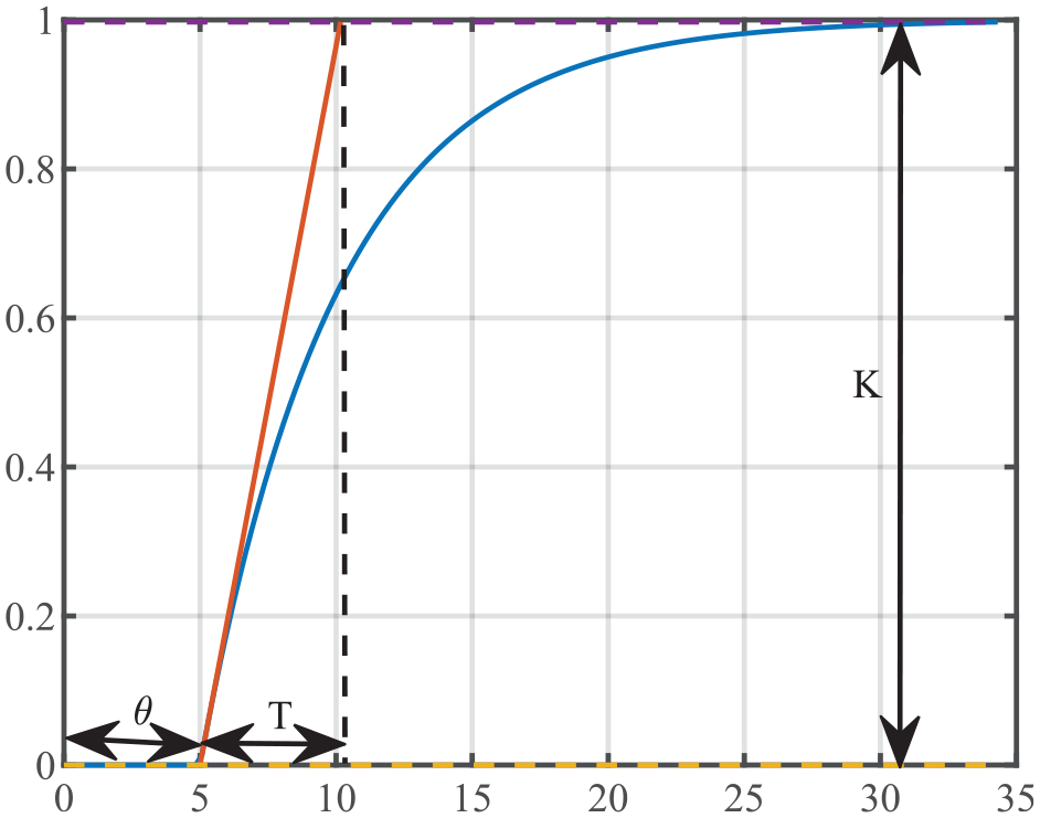
Calculation of
It can be observed that the above tuning rules are designed for a fixed value of robustness. These tuning rules can be modified with the IDA-2, as mentioned in equation (3). Equation (3) can be rewritten by substituting the above expression of
where
Selection of shifting constant parameter
The choice of the constant parameter
Consider a PID controller of the following form with the assumption
The above form of the PID controller can be realized if both the zeros are real that is
To satisfy the condition in equation (4), assume that the minimum value of
Substituting the value of
Substituting the obtained value of
Similarly, substituting the value of
Substituting the obtained value of
Simulation results
Proposed tuning rules are validated with the three simulation examples and one experiment on the temperature controller. Normalized dead time
when
Example 1: FOPTD process
The proposed tuning rule is validated using the FOPTD transfer function of the following form
where
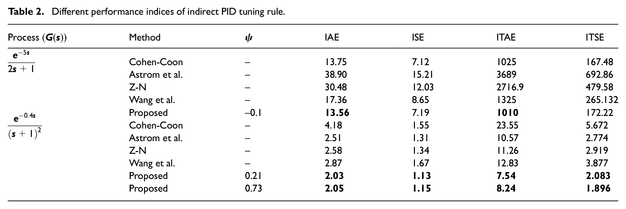
The normalized dead time
Response comparison of indirect PID tuning rule with Astrom, Cohen-Coon, Z-N, and Wang et al. tuning rule.

Different performance indices of indirect PID tuning rule.

Controller performance for Example 1: (a) step response of proposed controller and existing controllers and (b) effect of
Effect of

Example2: Second-order plus time-delay process
The following form of the second-order plus time-delay (SOPTD) process is considered. The same process has also been considered by Hang et al. (1991)
The identified FOPTD process of the above transfer function from the reaction curve is as follows
The value of normalized dead time

Controller performance for Example 2: (a) step response of proposed controller and existing controllers and (b) effect of
Example3: Higher-order plus time-delay process
The higher-order plus time-delay (HOPTD) process of the following form is considered.
Following is the identified FOPTD process of the above transfer function from the reaction curve
The value of normalized dead time
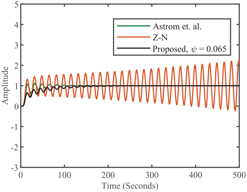
Step response of Example 3.
Experimental validation
An experimental setup of the temperature control laboratory depicted in Figure 5(a) is used to validate the proposed method. The first-order time-delay transfer function model of the temperature control system is obtained using the reaction curve method. Equation (9) represents the temperature control system’s first-order transfer function model
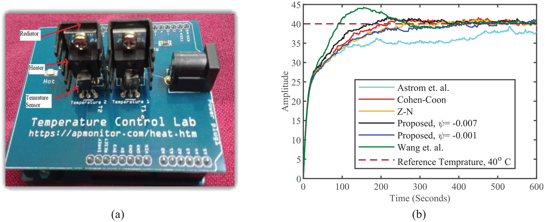
Experimental setup and performance: (a) experimental temperature control device and (b) experimental result with proposed PID and existing PID controller tuning method.
For the identified transfer function model, the PID controller is designed by using the proposed indirect PID tuning rule shown in Table 4. The designed Indirect PID controller parameter is given in Table 5. The suitable range for the
Indirect PID tuning rules.

PID controller parameter for (9).

Conclusion
A new response-based PID controller tuning rule is proposed in this article. It becomes possible to adjust the phase margin and maximum sensitivity of the process without direct tuning the controller with the help of the IDA-2 method. A too-low and too-high value of
Footnotes
Declaration of conflicting interests
The author(s) declared no potential conflicts of interest with respect to the research, authorship, and/or publication of this article.
Funding
The author(s) received no financial support for the research, authorship, and/or publication of this article.
