
Abstract
Autonomous navigation is one of the most critical technologies for ships. The initial alignment technology is the key to achieving autonomous navigation. However, the wind and waves on the sea seriously affect the initial alignment accuracy and even make it divergent. In this paper, a polarization navigation system/geomagnetic navigation system (PNS/GMNS)–assisted initial alignment method based on wind and wave disturbance model is proposed with applications of ships under wind and wave conditions. At the coarse alignment stage, a vector-weighted matching algorithm is designed in response to the difference in sensor measurement errors, which can solve the problem of error divergence in traditional methods. At the fine alignment stage, the proposed wind and wave disturbance model is introduced into the integrated navigation model. Subsequently, the Kalman filter is performed to estimate system states, which significantly improves the initial alignment accuracy. Finally, the effectiveness of the proposed method is verified by both simulation and experiment studies.
Keywords
Introduction
Autonomous navigation technology is of significance in promoting the development of many fields including marine energy exploration, marine trade, and marine science. The initial alignment is the process of establishing the initial reference before the shipborne navigation system works. On one hand, it allows the navigation system to work promptly. On the other hand, it can attenuate the detrimental influence of the initial error on the navigation solution. In a common practice, the initial alignment includes coarse alignment and fine alignment.
The coarse alignment technique is developed on the basis of the inertial navigation system (INS), by which the three-axis attitude can be determined. The core vectors are the angular velocity vector of the earth’s rotation and the gravity acceleration vector, respectively. Fang and Wan (1996), Tian et al. (2020), and Acharya et al. (2011) have deeply studied the inertial navigation–based self-alignment method. Under the condition of a stationary base, these methods can efficiently complete the initial alignment. However, the presence of wind and waves on the sea surface induces the hull shaking. In this case, the stationary base assumption is no longer satisfied. Especially when the sea state is rough, hull shaking prevents the gyroscope and the accelerometer from obtaining measurement data precisely. As a result, the performance of the initial alignment is deteriorated. In response to this problem, a fast alignment method based on quaternion pose estimation is achieved by creating infinite vector observations (Jameian et al., 2019). A dual-position rotation method is designed for a strap-down inertial navigation system (SINS) under oscillation conditions in Liu et al. (2019). However, in the case of strong sea wind and waves, the self-alignment method based on the INS can no longer effectively handle wind and wave-induced errors. Therefore, extra navigation information is introduced to the initial alignment process. The velocity vector provided by the global positioning system (GPS) is used in Silson (2011), which improves the alignment accuracy effectively. In order to achieve robust alignment, the carrier position trajectory is adopted for the alignment of the SINS/GPS (Xu et al., 2019). In addition to GPS, the Doppler velocity Log (DVL) (Xu et al., 2017b), tilt sensor (Gao et al., 2004), astronomical navigation system (Lu et al., 2017), and odometer (Xu et al., 2017a) are employed to assist initial alignment.
With respect to the fine alignment process, the existing research can be mainly divided into two types. (1) The wind and wave disturbance is treated as harmful measurements. Thereby, plenty of robust filtering methods are presented to suppress wind and wave disturbance. On this basis, a fading factor is designed within the fine alignment filtering process to suppress harmful observation data and noise (Chang, 2014b). A recursive fading-memory filter is proposed to track discontinuous state changes in the fine alignment process (Chang, 2014a). These methods can improve the initial alignment accuracy under wind and wave conditions to a certain extent. (2) The alignment problem in wind and wave scenarios is transformed to a nonlinear estimation problem with large misalignment angles. An improved second-order extended Kalman filter (EKF) is proposed (Mei et al., 2016) to achieve an initial alignment technique for arbitrary pose conditions without initial values. A Kalman filter (KF)/EKF hybrid algorithm is exploited (Zhao and Qin, 2020) to address the problem of the large computational complexity of nonlinear filtering. To further improve the alignment speed, an adaptive unscented Kalman filter (AUKF) is proposed in Rahimi et al. (2021). The dynamic acceleration is employed to adjust the gain parameters adaptively. In Du et al. (2016), the azimuth misalignment angle can be estimated using a disturbance observer. Furthermore, a disturbance observer–based KF is designed, which effectively improves the initial alignment rate. Concerning the modeling issue of wind and wave disturbances, most of the existing research works are investigated from an acoustic perspective. For high-frequency wind and waves, the representative acoustic model is the APL waves model (Hanson and Phillips, 2001). With respect to low-frequency wind and waves, the mature wind and wave acoustic models include the Koopman–Ferrar model (Kuperman and Ferla, 1985) and the Knudsen spectral model (Dongari et al., 2011). To sum up, the existing research on fine alignment under wind and wave conditions mainly includes two treatments. Either consider wind and wave disturbance as detrimental measurements or as large misalignment errors. However, the modeling of the wind and wave disturbance is still insufficient.
In the migration activity of the marine organisms (Cochran et al., 2004; Lohmann et al., 2004; Mäthger et al., 2011), polarization and geomagnetic information is of great support to navigation. Recent studies have also revealed the applicability of polarization information (De Croon et al., 2022; Yang et al., 2019; Zhang et al., 2021). In the work of Zhang et al. (2022), the integration of SINS/polarization navigation system (PNS)/geomagnetic navigation system (GMNS) has been considered to achieve three-dimensional attitude determination. In the strategy, the wind and wave disturbances are treated as unknown feature interference, so the interference features were not considered enough. In this paper, the PNS and GMNS are exploited to assist the initial alignment of the integrated system. The polarization vector is the one distributed across the sky concerning the astronomical position of the sun. The geomagnetic vector is stably distributed in a certain height space on the earth surface. Once the two are applied to the initial alignment, the integrated navigation system can be enhanced from the perspectives of autonomy and concealment. Furthermore, at the fine alignment stage, the sensor accuracy correlation factor is designed and a disturbance model is established in consideration of both wind and wave impacts. Subsequently, the alignment accuracy can be significantly improved by filtering. The technical advantages of the proposed method can be summarized as follows:
At the coarse alignment stage, the sun vector and the geomagnetic vector are adopted for the alignment solution. Benefiting from the rich information (Remark 1) in the polarization and geomagnetic fields, the solution error caused by the too-small angle between the two vectors can be avoided (Remark 2). In the presence of huge difference existing in sensor precision, a vector-weighted matching algorithm is developed to achieve better tolerance for coarse alignment. Consequently, a reliable coarse alignment for the ship can be achieved.
At the fine alignment stage, modeling research on wind and wave disturbances is carried out. The sensor accuracy correlation factor is designed, while a wind and wave disturbance model suitable for the initial alignment process is established. Subsequently, by combining the inertial navigation error model, wind and wave disturbances can be estimated effectively. Therefore, the alignment accuracy can be significantly improved.
The remainder of this paper is organized as follows. In section “PNS/GMNS-assisted initial alignment method based on wind and wave disturbance model,” the PNS/GMNS-assisted initial alignment method based on the wind and wave disturbance model is elaborated step by step. In section “Simulation and experiment,” the performance of the proposed algorithm is verified by both numerical simulation and field experiments. Finally, a brief conclusion is addressed in the final section “Conclusion.”
PNS/GMNS-assisted initial alignment method based on wind and wave disturbance model
In order to overcome the difficulty of initial alignment of ships in unfamiliar seas with wind and waves, the polarization vector and geomagnetic vector are introduced to assist in alignment. A matching algorithm is presented since the precision of polarization measurement and geomagnetic measurement may not be consistent. Thereby, the coarse alignment algorithm can achieve better robustness to the inconsistency of sensors’ accuracy. Furthermore, at the fine alignment stage, the information of PNS and GMNS is used to correct the navigation information of SINS. Based on a more accurate wind and wave disturbance model, The overall framework of the proposed algorithm is shown in Figure 1. The coordinate systems used in this paper and the spatial position relationship among them are shown in Figures 2 and 3.
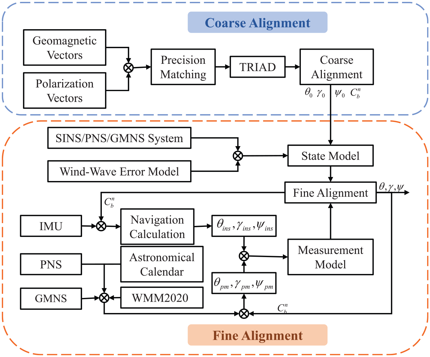
The structure diagram of coarse alignment based on PNS/GMNS and fine alignment based on wind and wave disturbance model.
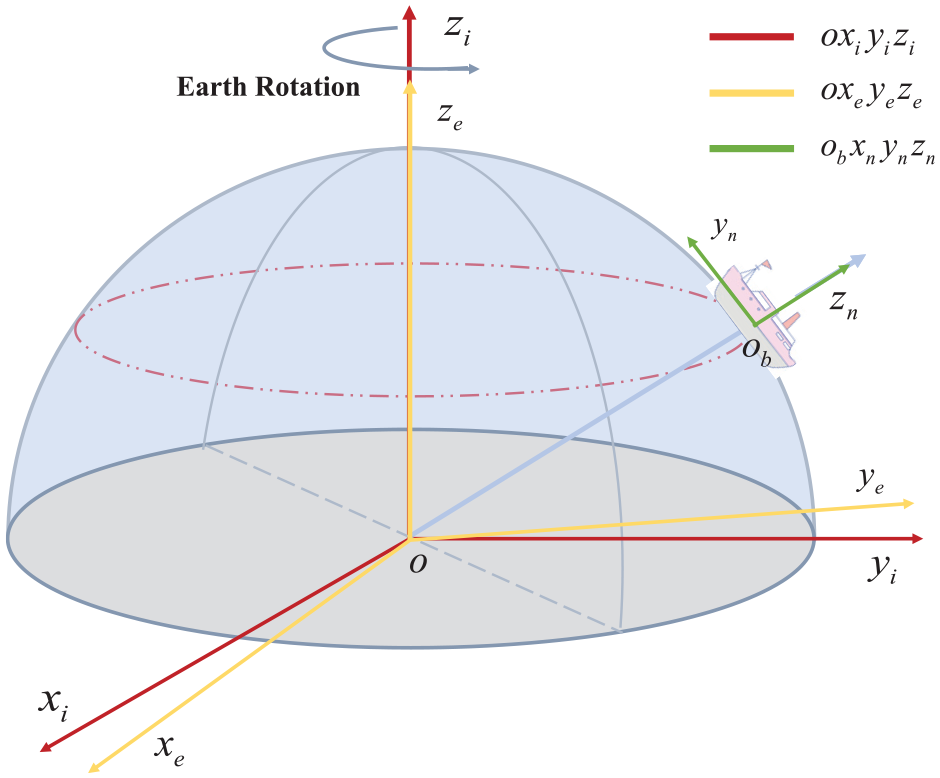
The coordinate systems relative to the Earth.

The coordinate systems relative to the ship.
PNS/GMNS-based double vector coarse alignment algorithm
Inspired by the navigation skills of Arctic terns, the polarization and geomagnetic vectors are introduced to design a double vector–assisted initial alignment method. Thereby, the interference of the hull motion can be isolated, and reliable coarse alignment can be achieved.
Obtain the sun vector and geomagnetic vector in
frame
The sky polarization field is a regularly distributed vector field. It is formed by the scattering of the sunlight in the atmosphere. The polarization vectors in

where
Similarly, the three-axis magnetometer can directly obtain the geomagnetic vector in

where
Obtain the sun vector and geomagnetic vector in
frame
The geographic coordinate system (East-North-Up) is adopted as the navigation coordinate system. The solar astronomical almanac can reflect the solar space position information, precession, and nutation. The sun vector in

WMM is a joint product of the United States’ National Geospatial-Intelligence Agency (NGA) and the United Kingdom’s Defence Geographic Centre (DGC) (Chulliat et al., 2020). It has been widely used as a standard model in the field of navigation and geological exploration. According to the real-time position and time information of the ship, the geomagnetic vector in

where
Vector-weighted matching algorithm
In the alignment solution, the measurement accuracy of PNS and GMNS may be quite different, which can induce a large error of the coarse alignment based on the tri-axial attitude determination (TRIAD) algorithm. To address the issue, the vector-weighted matching algorithm is designed according to the measurement standard deviation (STD) of the two subsystems.
The sun vector in
where
For the GMNS, once the magnetometer is selected, the STD of the errors in the corresponding geomagnetic vector
where
Furthermore, construct the measurement vector

Correspondingly, the vector in

Next, construct the second set of corresponding vectors


Consequently, as given in equations (7)–(10), the two sets of corresponding vectors in

where
Fine alignment based on wind and wave disturbance model
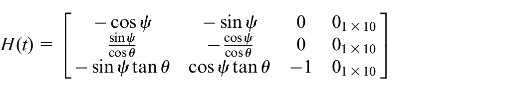
The initial attitude rotation matrix
Modeling of sea surface wind and wave disturbances
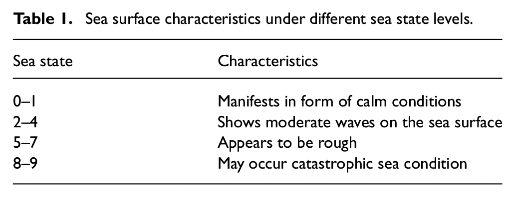
There exist wind and wave motions acting on the sea surface in most cases. According to the statistical characteristics of wave height, period, and spectrum, the sea states are classified into 10 levels by the World Meteorological Organization (WMO). The sea surface characteristics under different sea state levels are shown in Table 1. As a result of the periodic characteristics of wind and waves, most studies describe wind and waves as quasi-sine characteristic functions (Dongari et al., 2011; Hanson and Phillips, 2001; Kuperman and Ferla, 1985).
Sea surface characteristics under different sea state levels.
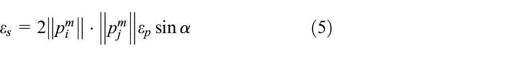
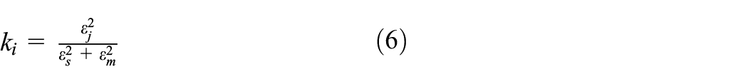
In terms of the research (Chen, 2016) on the measured wind and waves in the South China Sea, the sensor accuracy correlation factor
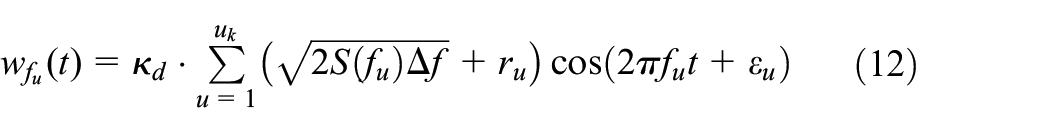
where
This study concerns the wind and wave conditions at the level second to fifth. The corresponding average frequency spectrum (Mabrouk, 2010) is as follows:
The second-degree wind:
The third-degree wind:
The fourth-degree wind:
The fifth-degree wind:
Using the proposed wind and wave disturbance model, in the case of the fifth degree wind and
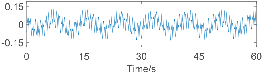
Wind and wave noise generated by the wind and wave disturbance model at the level fifth.
Fine alignment filtering algorithm based on wind and wave disturbance model
In this section, the KF framework is used for fine alignment. Focusing on the ship navigation system, 13-dimensional state

where

With the updated measurement data, two sets of three-dimensional attitude angles can be calculated by the coarse alignment method and SINS. The difference between them is adopted as the measurement of the SINS/PNS/GMNS system. Thus, the measurement model can be obtained as
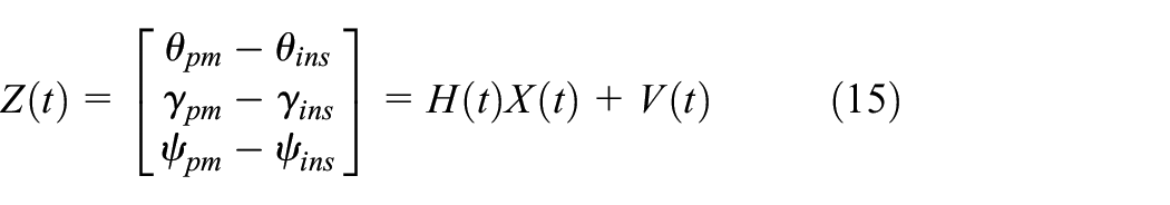
where
Simulation and experiment
In order to verify the performance of the proposed initial alignment algorithm, numerical and experimental tests are carried out under ship mooring and sailing conditions, respectively.
Simulation results and analysis
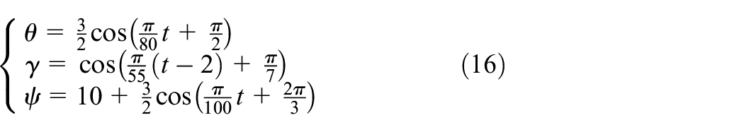
When the ship is in the mooring state, under the conditions of wind and waves, the ship performs a regular periodic rocking motion. The position of the ship is set as (40°N,120°E). The simulation time lasted 11 minutes. The rocking motion of the ship is set as
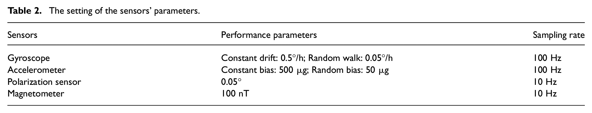
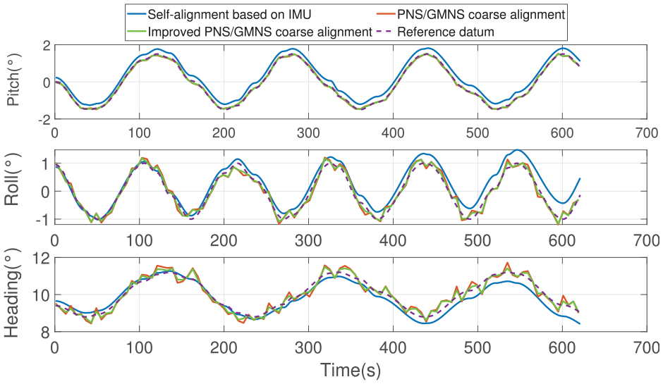
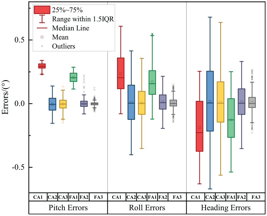
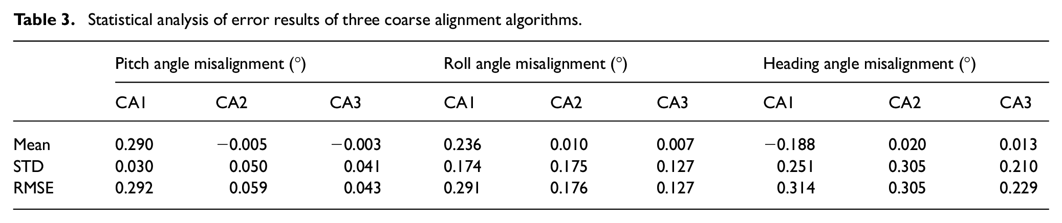
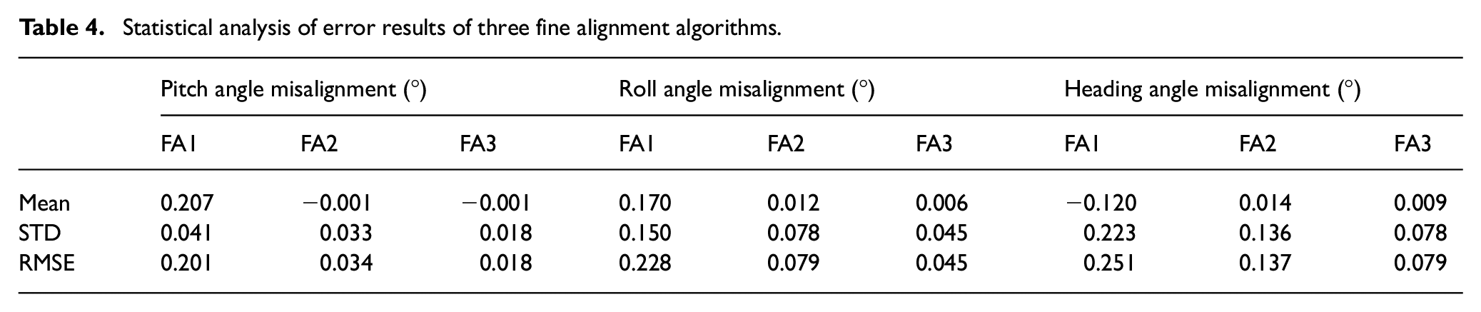
The specifications of the selected sensors are listed in Table 2. Based on the simulation data, the traditional IMU-based alignment algorithm (CA1), the PNS/GMNS dual vector algorithm (CA2), and the improved PNS/GMNS dual vector algorithm (CA3) are used for coarse alignment. The coarse alignment results of the three methods are shown in Figures 5 and 6. The traditional IMU-based KF (FA1), the KF based on the difference between the PNS/GMNS and SINS misalignment angles (FA2), and the filter based on the wind and wave disturbance model and misalignment angle difference (FA3) are adopted for fine alignment. The fine alignment results are illustrated in Figures 7 and 8. The error statistics of coarse alignment and fine alignment are shown in Figures 9 and 10 and Tables 3 and 4.
The setting of the sensors’ parameters.
Comparison of three-dimensional attitude coarse alignment results.
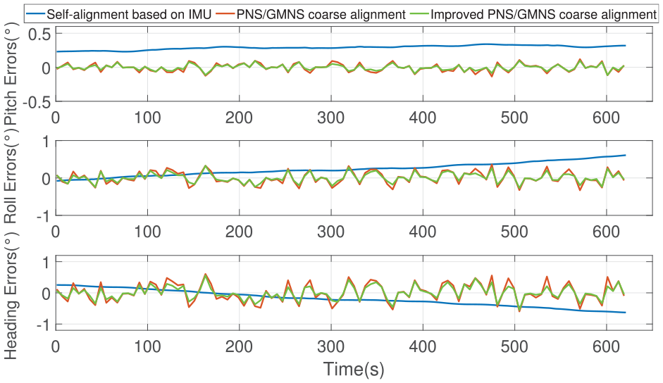
Comparison of coarse alignment errors results.
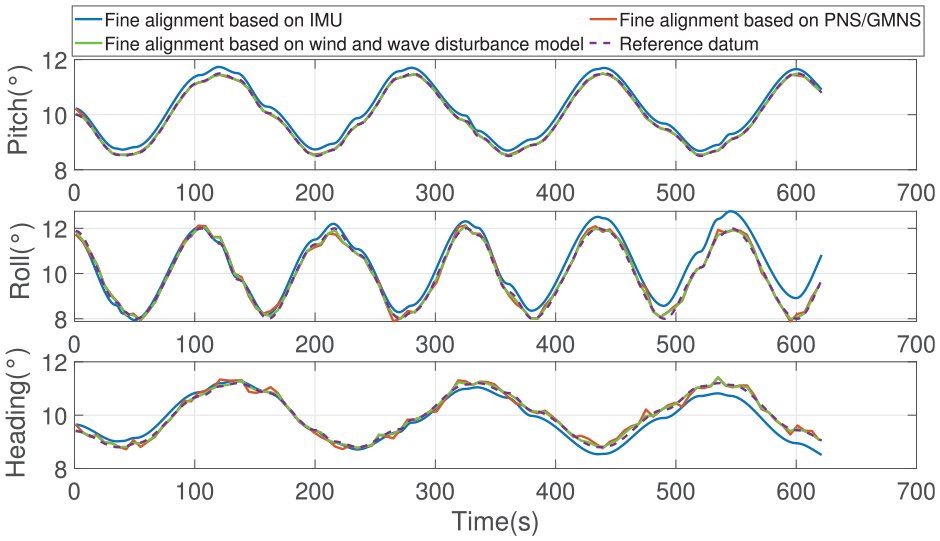
Comparison of three-dimensional attitude fine alignment results.
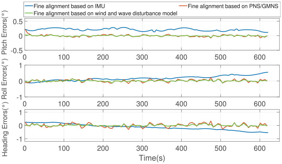
Comparison of fine alignment errors results.
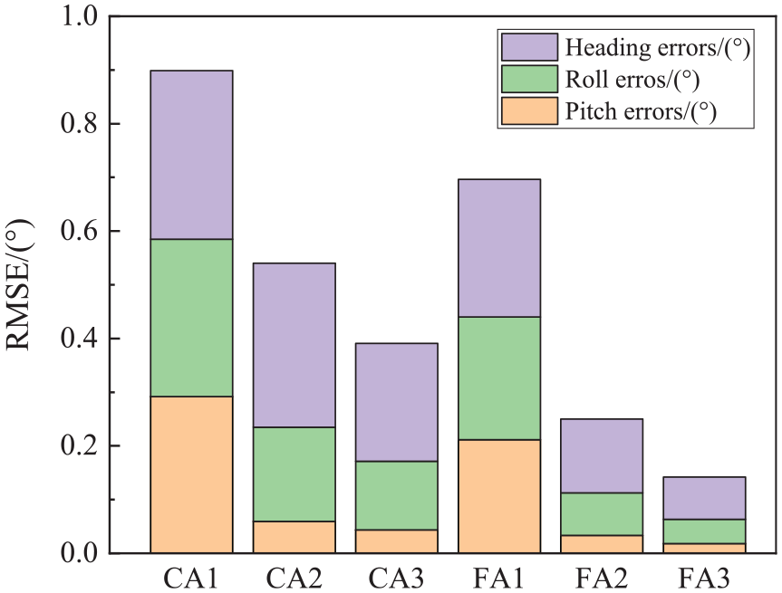
RMSE of alignment errors.
Boxplot of alignment errors.
Statistical analysis of error results of three coarse alignment algorithms.
Statistical analysis of error results of three fine alignment algorithms.
Combined with the results of the three-dimensional attitude angle error of the ship in Figure 6, the three-dimensional attitude angle of the ship periodically swings under the conditions of wind and waves. In this scenario, the coarse alignment method CA1 can no longer accurately perceive the angular velocity vector of the earth’s rotation and the gravity acceleration vector. Correspondingly, the proposed alignment algorithm CA2 and the improved CA3 algorithm based on precision matching do not diverge. As can be seen from Figures 9 and 10 and Table 3, in terms of the mean value of the alignment error, as compared to the traditional alignment algorithm CA1, the alignment algorithm CA2 improves the accuracy of the three-dimensional attitude angle by more than 89.36%. On this basis, the accuracy of the CA3 alignment algorithm based on precision matching for the pitch angle, roll angle, and heading angle is further improved by 40.00%, 30.00%, and 35.00%, respectively. The simulation results show that the algorithms CA2 and CA3 have stronger anti-divergence ability. In terms of alignment error STD, the accuracy of the three algorithms is roughly the same. The reason for this result is that the IMU data are disturbed by wind and wave noise. While the measurement data of PNS and GMNS are disturbed by sea surface reflection and weather conditions. Therefore, further fine alignment is indispensable. In terms of root mean square error (RMSE) of alignment error, in opposition to the traditional algorithm CA1, the accuracy of the pitch angle, roll angle, and heading angle of the alignment algorithm CA2 is improved by 79.70%, 39.52%, and 2.87%, respectively. On this basis, the alignment algorithm CA3 is further improved by 27.12%, 27.87%, and 24.92%, respectively. The simulation results verify the effectiveness of the proposed coarse alignment algorithm in improving accuracy and anti-divergence performance.
The fine alignment results and errors are shown in Figures 7 and 8. The alignment accuracy is significantly improved by the three fine alignment algorithms. Combined with the statistical characteristics of alignment errors (Figures 9 and 10 and Table 4), in terms of STD, compared with the fine alignment algorithm FA1, FA2 has improved the alignment accuracy in pitch angle, roll angle, and heading angle by 19.51%, 48.00%, and 39.01%, respectively. In terms of RMSE, the performance is improved by 83.08%, 65.35%, and 45.42%, respectively. On this basis, the wind and wave disturbance is further modeled in the filter model, and the fine alignment algorithm FA3 is performed. The alignment accuracy of pitch angle, roll angle, and heading angle is improved in STD term by 45.45%, 42.31%, and 42.65%, respectively. In terms of RMSE, the accuracy is improved by 47.06%, 43.04%, and 42.34%, respectively.
In conclusion, the effectiveness of the proposed algorithm is verified by numerical simulation. In the coarse alignment stage, the auxiliary effects of polarization and geomagnetic information effectively resist the divergence of attitude angle errors. In the fine alignment stage, for the sake of the establishment of the wind and wave disturbance model, the initial alignment accuracy is significantly improved.
Experiment results and analysis
In order to further examine the performance of the proposed method, the experimental studies of the Xiangyanghong No. 1 scientific research ship in the Yellow Sea are carried out. On 9 September 2020, in the Yellow Sea, the research vessel Xiangyanghong No. 1 started sailing at 15:17:38. The maximum velocity during sailing is 10 kn. The starting position information is (36.58°N, 122.39°E, 8.6 m). The sea state of Yellow Sea is with light waves of 0.8–1.2 m. The navigation track of the Xiangyanghong No. 1 scientific research ship is depicted in Figure 11.
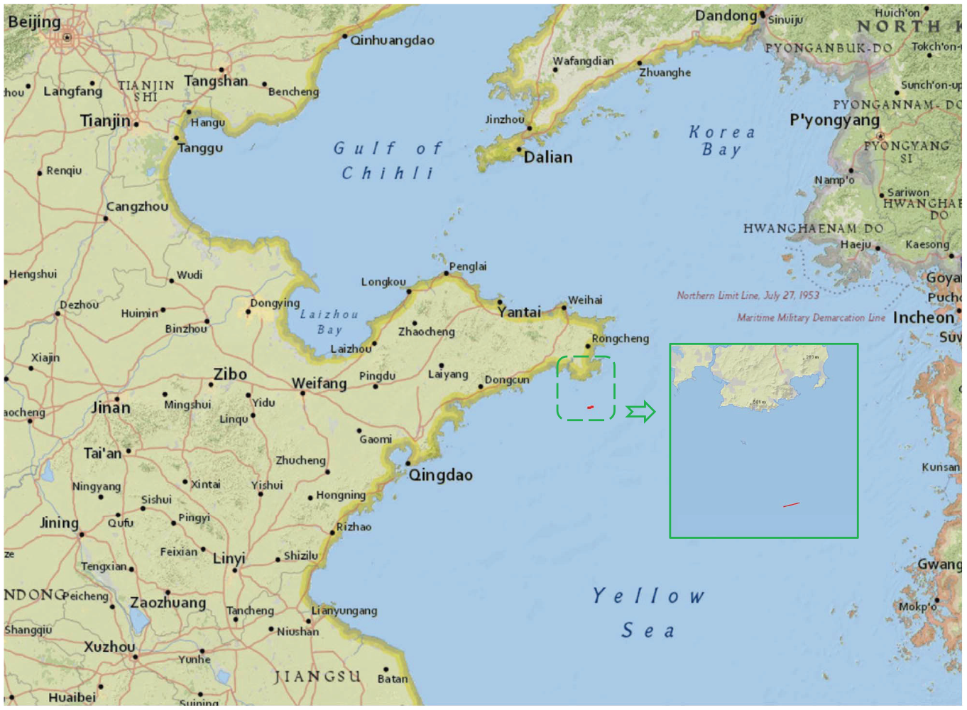
Navigation track of Xiangyanghong No. 1 scientific research ship in the Yellow Sea.
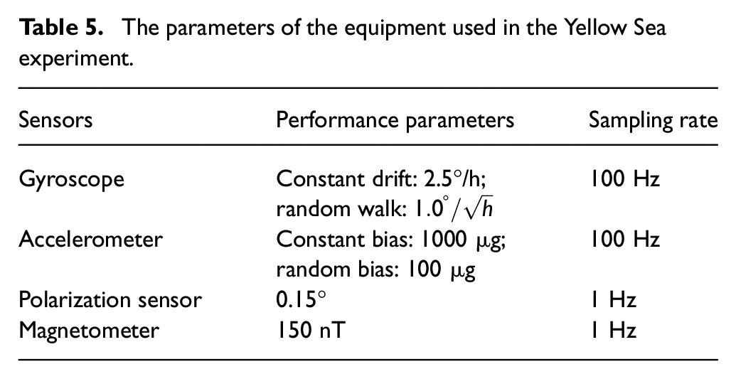
The experimental equipment is shown in Figure 12. The compound-eye polarization sensor and integrated navigation system (including inertial navigation and geomagnetic sensor) developed by our research group are adopted. During the experiment, the real-time differential calculation of dual GPS antenna data is used to provide a reference datum. The parameters of each sensor are listed in Table 5.
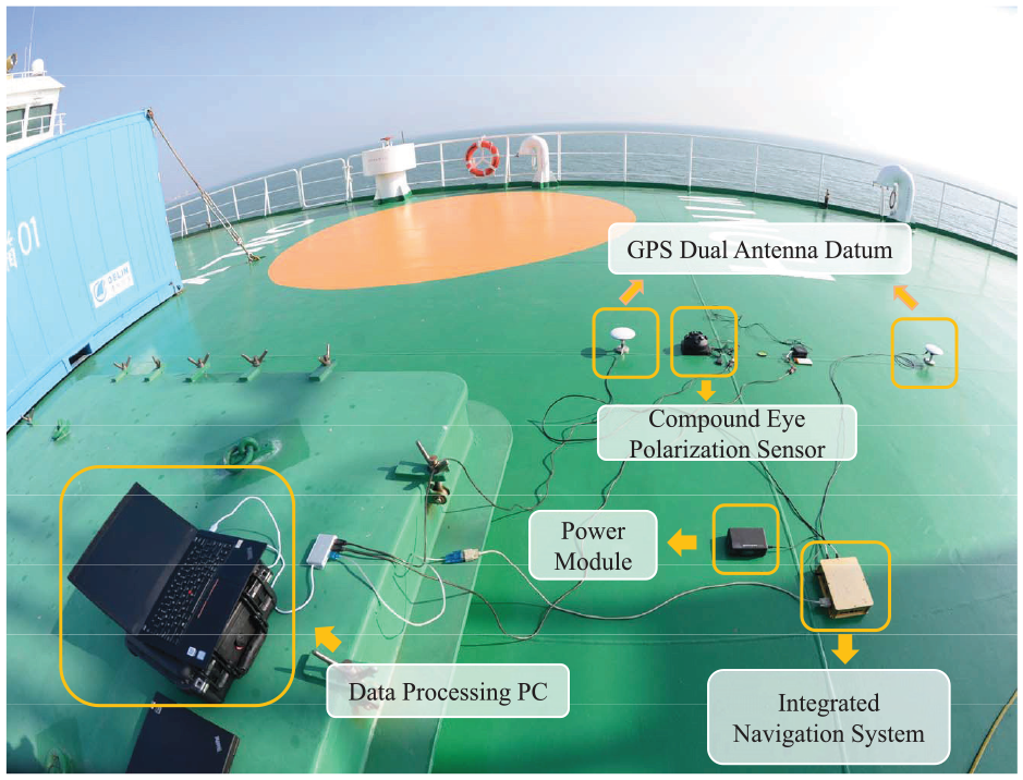
The equipment used in the Yellow Sea experiment.
The parameters of the equipment used in the Yellow Sea experiment.
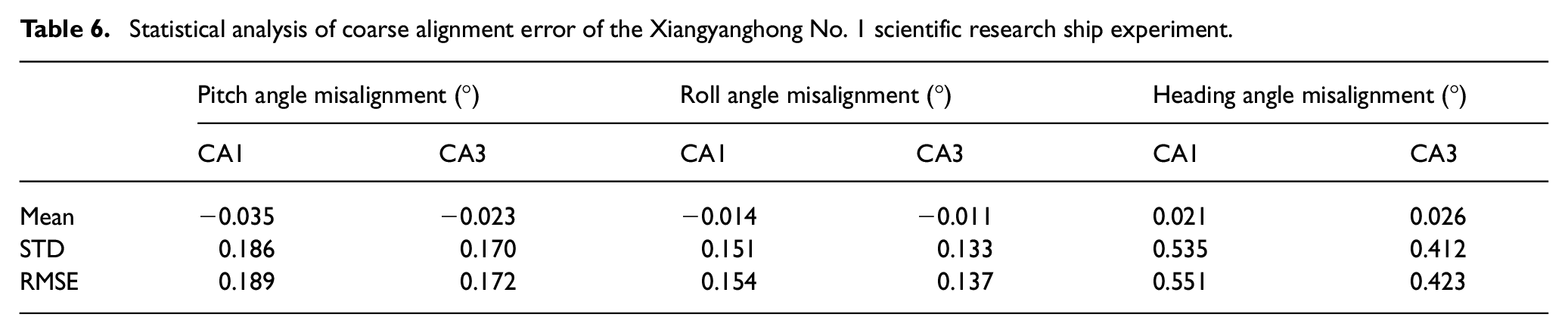
The coarse alignment algorithms CA1 and CA3 are selected in the experimental studies. The results of coarse alignment are shown in Figure 13 and Table 6. In the fine alignment process, the filtering algorithm FA1 and the filtering algorithm FA3 are selected to process the data. The results of fine alignment are illustrated in Figure 14 and Table 7. The error characteristics of the alignment results are illustrated in Figures 15 and 16.
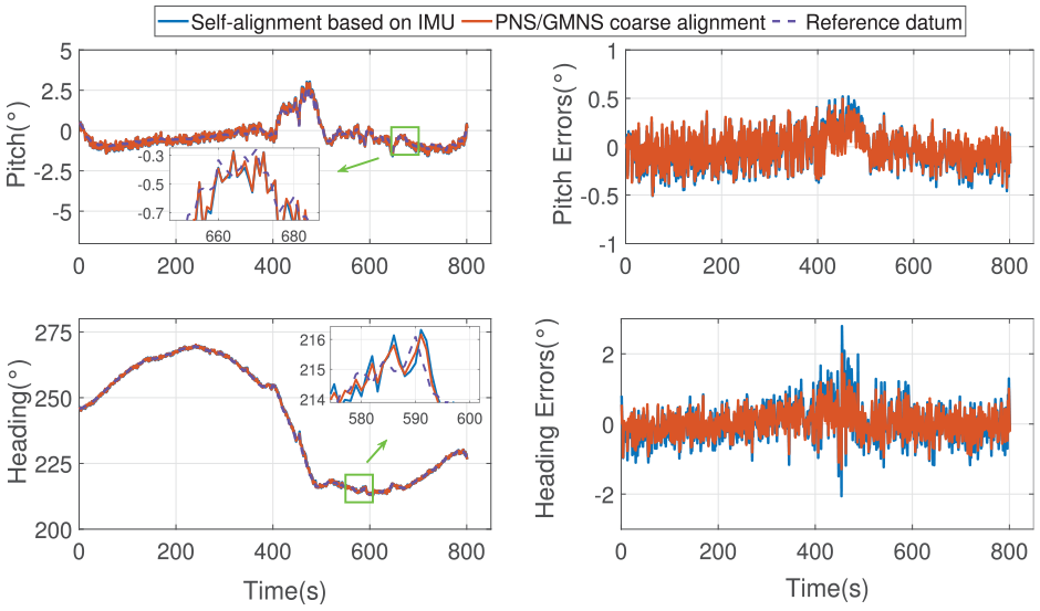
Coarse alignment results and coarse alignment errors of pitch angle and heading angle in the Yellow Sea experiment.
Statistical analysis of coarse alignment error of the Xiangyanghong No. 1 scientific research ship experiment.
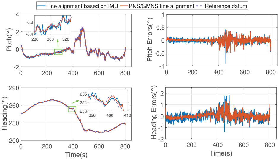
Fine alignment results and fine alignment errors of pitch angle and heading angle in the Yellow Sea experiment.
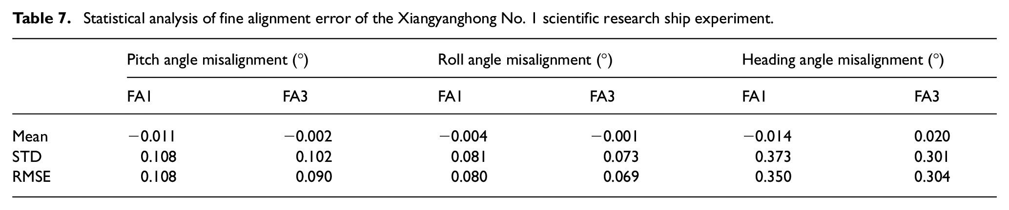
Statistical analysis of fine alignment error of the Xiangyanghong No. 1 scientific research ship experiment.
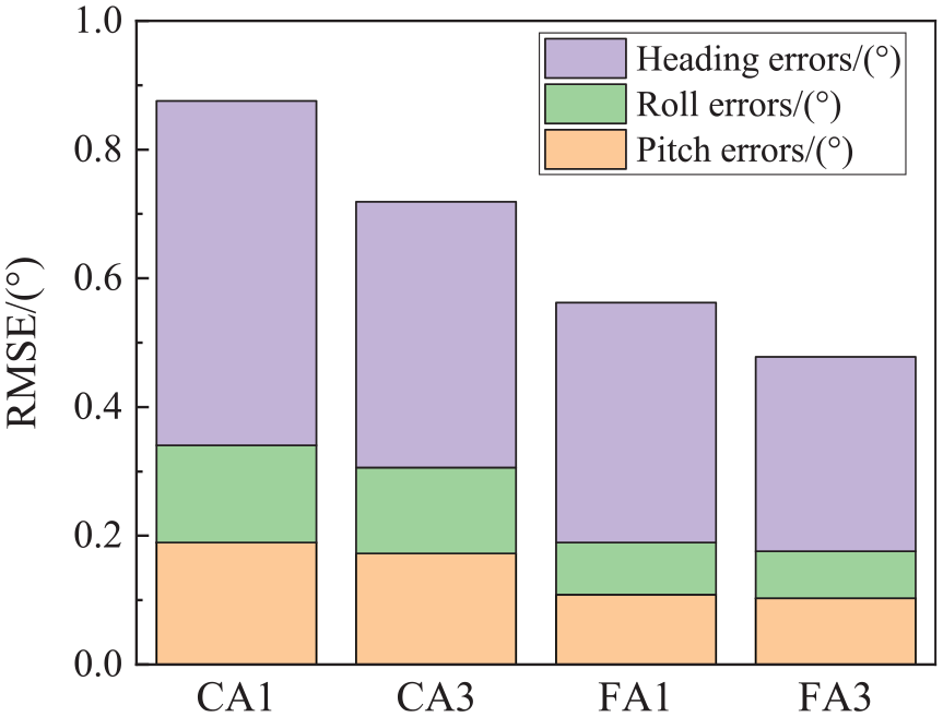
RMSE of alignment errors in the Xiangyanghong No. 1 scientific research ship experiment.
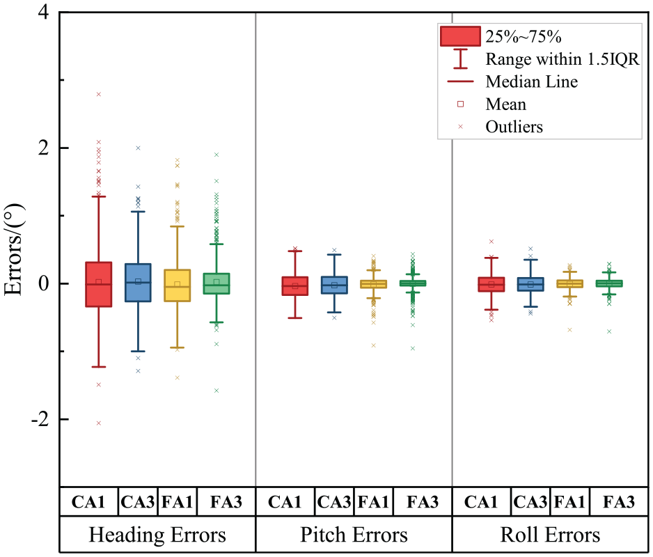
Boxplot of alignment errors in the Xiangyanghong No. 1 scientific research ship experiment.
From Figures 13 and 14 and Table 6, during the sailing process of the ship, one large wind and wave take place around 470 seconds. In this scenario, the IMU-based coarse alignment algorithm (CA1) and the precision matching–based improved PNS/GMNS coarse alignment algorithm (CA3) are applied to process the experimental data. The accuracy of the alignment results of pitch and roll angles is basically the same. In comparison of CA1, CA3 is able to improve the heading angle alignment result by 23.00% (STD) and 23.23% (RMSE). This result confirms that the coarse alignment method proposed in this paper outperforms the traditional IMU-based coarse alignment method.
The fine alignment results and fine alignment errors are displayed in Figure 14 and Table 7. Based on Figures 15 and 16, by virtue of the fine alignment processing, the performance of alignment results preserved by the two methods is considerably improved compared to the coarse alignment results. From the perspective of alignment error RMSE, the accuracy of the proposed fine alignment algorithm FA3 can achieve 0.09° (pitch angle), 0.07° (roll angle), and 0.30° (heading angle), respectively. Compared with the fine alignment algorithm (FA1) based on IMU gravity information, the enhancement rates are 16.67%, 16.25%, and 13.14%, respectively.
In summary, the applicability of the proposed method is validated through the experiment of the Xiangyanghong No. 1 scientific research vessel in the Yellow Sea. The proposed method can be applied to the initial alignment of ships in the presence of wind and waves.
Conclusion
Inspired by marine migratory animals, the polarization information and geomagnetic information are introduced into the alignment system to overcome the difficulty resulting from the sea wind and waves. In the process of coarse alignment, a vector-weighted matching algorithm is proposed for the difference in sensor measurement accuracy. Based on this algorithm, the new alignment vectors are constructed by combining the sun vector and the geomagnetic vector, thereby achieving the anti-divergence alignment. In the process of fine alignment, the wind and wave disturbance model is established and subsequently combined with the integrated navigation model. The wind and wave noise is considered in the filtering estimation, which significantly improves the alignment accuracy. Finally, simulation and the Yellow Sea experiment verify the proposed method’s effectiveness. The results show that, compared with the traditional IMU-based self-alignment method, the proposed method can perform a high-precision alignment no matter in the ship’s mooring or sailing state. In future research, sensor optimization, installation error compensation, and environmental disturbance modeling will be taken into consideration for higher alignment accuracy.
Footnotes
Appendix
Nomenclature table
| With respect to x-, y-, and z-directions of according coordinate system | |
| Inertial coordinate system, earth coordinate system, navigation coordinate system, body coordinate system, and module coordinate system | |
| The sun vector, geomagnetic vector, and polarization vector | |
| and | The solar zenith angle and solar azimuth angle |
| , , ; ; , | The STD of the errors of sun vector, polarization vector, and geomagnetic vector; the angle between two polarizationvectors; the matching weighting coefficient of sun vector and geomagnetic vector |
| , , , , , | The wind and wave disturbance item, the wind and wave dimension parameter matrix, the superposition upper limit of random sinusoidal signals, the average frequency spectrum, the frequency of the wind and wave, the random amplitude, and the random phase |
| , , ; , ; , ; , , ; , , | The misalignment angles in the east, north, and sky directions; the east and north velocity errors; the latitude and longitude errors; the three-axis constant drift of the gyroscope; the three-axis zero offsets of the accelerometer |
| , , ; , , | The three-dimensional attitude angles calculated by the coarse alignment method; the three-dimensional attitude anglescalculated by SINS |
Acknowledgements
The authors express their sincere gratitude to the Editor-in-Chief, the Associate Editor, and the anonymous reviewers whose insightful comments have helped to improve the quality of this paper considerably.
Declaration of conflicting interests
The author(s) declared no potential conflicts of interest with respect to the research, authorship, and/or publication of this article.
Funding
The author(s) disclosed receipt of the following financial support for the research, authorship, and/or publication of this article: This research was supported by the National Key R&D Program of China under grant 2020YFA0711200, the National Natural Science Foundation of China under Grants 62003016, 61751302, 61833013, and 61973012, and the Hangzhou Science and Technology Major Innovation Projects under Grant 20182014B06.