
Abstract
This paper presents a hybrid control strategy for an induction motor (IM) organized into two nested loops. In the outer loop, an adaptive artificial neural network-based proportional-integral-derivative (ANN-PID) controller is used for speed control. The ANN-PID is divided into two stages: the first stage includes an adaptive ANN speed estimator, and the second stage includes an adaptation algorithm that fine-tunes both the weights and biases of the ANN estimator and the parameters of the PID controller. In the internal loop, a predictive current controller is used to control IM currents using neural networks. Specifically, the neural predictive controller (NPC) approaches the control problem by presenting it as an optimization problem using a neural predictor for IM currents. The considered objective function includes two elements: the current tracking error and the electromagnetic torque ripple. This function is computed over a given time horizon informed by predictions of IM currents. The particle swarm optimization (PSO) algorithm is applied to determine the optimal solution for this optimization task. The effectiveness of the hybrid control scheme is demonstrated by simulation results obtained using Matlab/Simulink, highlighting its superiority over conventional control methods. The proposed hybrid control is characterized by a reduction in torque ripple and overshoot, while also showing robustness to variations in load, rotor resistance, and rotor inductance. Comparisons with an ANN controller and a fuzzy PI controller further demonstrate the superior performance of the hybrid controller in handling nonlinear dynamics and maintaining control accuracy under various operating scenarios.
Keywords
Introduction
Motivation
Induction motors (IMs) are increasingly preferred over DC motors in a wide range of industrial and commercial applications. This shift is due in large part to the lower manufacturing costs of IM, which eliminate the need for switches and brushes—components that are not only expensive but also require frequent maintenance. In addition, IM offers several other benefits, including reduced maintenance costs and lower weight (Hassan et al., 2023). The versatility of IMs is evident in their application in various flux such as household appliances, HVAC systems, aerodynamic mechanisms, industrial servomotors, and electric vehicles. However, their speed control is more difficult than that of the above-mentioned DC motors (Singh et al., 2018). This led to the development of vector control by Blaschke and Hasse, which provides more effective control. This method, which is similar to the control of DC motors with independent excitation, manages both flux and torque independently (Fatima et al., 2016). It is particularly effective in IMs, where the stator and rotor flux intersect nonlinearly, unlike the fixed orthogonal flux in DC motors. This advancement in control technology enhances the practical applicability and efficiency of squirrel-cage IMs in various environments (Fatima et al., 2016; Hassan et al., 2023; Le-Huy, 1999).
Related works
Direct torque control (DTC) and field-oriented control (FOC) are effective methods for speed control in IMs. While FOC is known for its fast response and high efficiency, it is sensitive to parameter variations (Ouadi et al., 2010; Wang et al., 2023). Conversely, DTC is known for its robustness, especially in adapting to parameter changes. The performance of DTC and FOC in different motor control scenarios is significantly influenced by their different characteristics. To improve their functionality, especially in terms of reducing sensitivity to environmental changes and changes in motor parameters such as those caused by temperature variations, magnetic saturation, and mechanical load variations (Boumaalif and Ouadi, 2023; Song et al., 2017). The implementation of advanced controllers is critical (Devanshu et al., 2022; Mhaisgawali and Muley, 2013; Raveendra and Aswini, 2018). These controllers can be broadly categorized into three types, each offering unique approaches to managing and optimizing the performance of DTC and FOC in IM drives. The first category is model-based controllers (Hassan et al., 2023; Song et al., 2017). These controllers employ a mathematical model of the system to generate control signals for a source voltage inverter, thereby facilitating the control of an IM’s speed. They are classified into two subclasses: (a) linear controllers, which are known for their simplicity, straightforward design process, and effectiveness in IM drives under minor disturbances at a specific operating point. Among the linear controllers, the proportional-integral (PI) controller is the widely utilized control strategy in both industrial applications and the relevant literature, as detailed in the work by Raveendra and Aswini (2018) and Mhaisgawali and Muley (2013) Another well-known linear controller is linear model predictive control (MPC), which is renowned for its ability to optimize control. MPC predicts future system behavior using a linear model of IMs and adeptly manages multiple inputs and outputs within specific constraints, guided by an objective function (Bašić et al., 2023; Zhang et al., 2016a, 2016b). Linear MPC and PI controllers are highly regarded for its precision and adaptability in challenging environments, which is essential for maintaining performance and compliance with operational limits. However, its effectiveness can be diminished by nonlinear dynamics and parametric variations in IMs due to magnetic saturation and thermal rise. Accurate management of prediction and control horizons is crucial in Linear MPC; incorrect settings can reduce system responsiveness and efficiency. The necessity for precise system modeling and parameter identification becomes even more challenging in the face of uncertainties and disturbances. PI controllers also face issues with overshoot and settling times during disturbances or transitional phases, which can affect motor control stability and precision (Le-Huy, 1999). In addition (b), the nonlinear controllers are designed to deal with the nonlinearities and inherent in IMs, particularly when operating far from their rated operating points or under significant disturbances (Barra et al., 2016). Among the nonlinear control techniques applied to IMs is the sliding mode control, which offers several advantages (Adireddy et al., 2022; Fatima et al., 2016). This type of controller is renowned for its robustness, reliably maintaining tracking performance despite external disturbances and uncertainties in model parameters. However, a significant limitation is the potential occurrence of the chattering phenomenon, as noted in references (Hassan et al., 2023). Chattering can degrade performance and risk damaging motor and converter components. The backstepping technique has been used in the design of IM controllers and offers advantages such as effective transient response and reduced electromechanical torque ripple (Sahu et al., 2021). However, the backstepping is sensitivity to parameter uncertainties and external disturbances. Additionally, these nonlinear controllers are particularly sensitive to the choice of sliding surface and control law, which can significantly impact their effectiveness (Sahu et al., 2021; Singh et al., 2018).
The second category includes rule-based controllers, which operate according to a set of predetermined rules or heuristics (Hassan et al., 2023). This category includes controllers such as fuzzy logic controllers (FLCs) used for IMs, which are known for their ability to improve control performance and robustness (Maghfiroh et al., 2023). However, hysteresis controllers are distinguished by their non-constant switching frequencies and the absence of a maximum frequency cap, which may lead to interference issues (Hota and Ramchand, 2019). FLCs also face challenges. A precise and consistent mathematical model of the motor is required, which becomes problematic due to the variability of motor parameters over time. The complexity of their rule bases is also recognized for increasing the computational burden, thereby delaying response times. Moreover, these controllers have been observed to be less effective in adapting to sudden changes in operating conditions. Such a lack of adaptability can significantly compromise the stability and performance of the motor (Hassan et al., 2023; Sahu et al., 2021).. The last category of controller types for IMs are data-based controllers that rely on system-generated data. The most popular tool used in this type of control is the artificial neural network (ANN) (Mahfoud et al., 2022). In the literature, there are two types of ANNs that are based on offline and online learning in real time. The first ANN, which has been commonly used in the literature, involves emulating previous controllers like MPC and PI. This process entails collecting data from the operation of the initial controller and using these data to train the ANN, which then replaces the original controllers. However, this approach has several limitations. First, since the ANN merely replicates the basic controller, it often exhibits only modest performance improvements. Another significant challenge is the difficulty in collecting a comprehensive database that accurately represents all modes of engine operation. Another application of ANN is to adapt the parameters of other controllers, such as adjusting the rules of fuzzy logic in ANFIS controllers (Areed et al., 2010; El-bakkouri et al., 2022) or tuning PID parameters (Taşören et al., 2020). These studies use ANN-PID and ANFIS controllers for IMs have several critical limitations, which is based on a static ANN. Both controllers suffer from complex tuning and limited adaptability, making it difficult to optimize settings and adapt to sudden system changes. In addition, both require extensive training data, which can be resource-intensive to acquire and prepare. The complexity of ANFIS models poses challenges for implementation and real-time operation, often requiring additional computing resources and expertise for deployment. Similar to other neural network-based approaches, ANFIS controllers also suffer from a lack of interpretability, making it difficult to understand the reasoning behind their decisions (Hassan et al., 2023; Sahu et al., 2021). The second is adaptive ANN controllers that learn to dynamically adjust their parameters, such as weights and biases, and to respond to changing conditions in real time. Both types are used in IM drives to provide effective control (Chetouani et al., 2023).
Contributions and organization
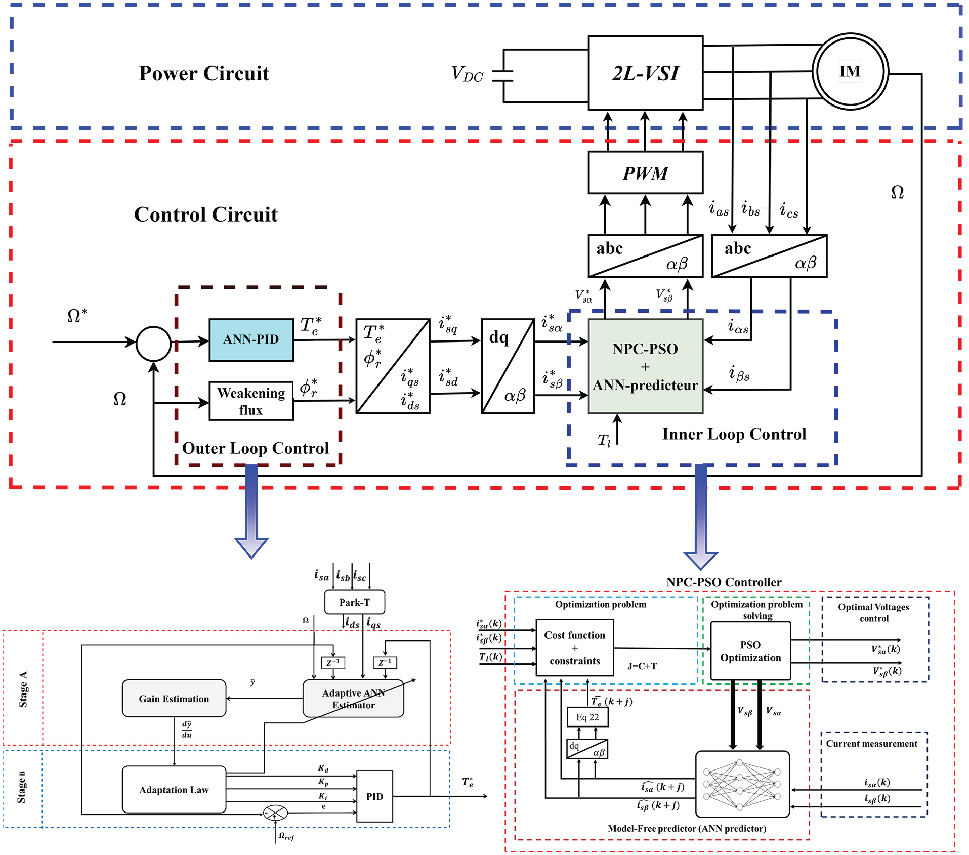
This paper presents the optimization and control of an IM using a novel hybrid approach. The control objective is to accurately track the speed and flux reference profiles of the IM via a two-level voltage source inverter (2L-VSI) converter. This is achieved using an imbricated loop strategy. The inner loop employs a neural predictive current controller (NPCC) that uses a multilayer perceptron (MLP) trained offline with historical data to predict the future current of the IM and adjust the stator voltage accordingly. This setup, combined with a particle swarm optimizer (PSO), provides effective real-time system control. The use of the NPCC in the inner loop results in improved transient speed performance and reduced electromagnetic torque harmonics (Hassan et al., 2023). In addition, an adaptive artificial neural network-based proportional-integral-derivative (ANN-PID) controller is integrated into the outer loop for refined speed control. This controller adjusts the PID parameters using an ANN, improving the overall robustness of the control system. The hybrid proposed controller presented in Figure 1 provides several key advantages, The present paper’s contribution includes the following:
Unlike the work by (Mhaisgawali and Muley, 2013; Olarinoye et al., 2019; Raveendra and Aswini, 2018), which used conventional PI/PID controllers that compute PI parameters based on a motor model around a fixed operation point, this paper presents an adaptive PID controller. This controller computes and updates its parameters in real time using an ANN.
Unlike the work by (Adireddy et al., 2022; Boumaalif and Ouadi, 2023; Chen et al., 2020; Ouadi et al., 2010), which employed nonlinear model-based regulators with fixed parameters for controlling the IM, this paper proposes two ANN-based regulators. These regulators have been designed with enhanced adaptability and robustness across all operational modes, with the objective of minimizing torque ripples.
Unlike the work by (Bašić et al., 2023; Shiravani et al., 2023; Wróbel et al., 2020), which employed MPC based on the Euler form for discretization and built the predictor for a short prediction horizon, this paper utilizes an ANN for prediction. The ANN was trained using inputs selected via a correlation matrix and structured in a cascade to predict the system’s behavior over a long prediction horizon. Furthermore, PSO was used to optimize the objective function expeditiously, thereby enhancing the transient regime of the IM.
Unlike the work by (Bašić et al., 2023; Garcia et al., 2016; Shiravani et al., 2023), which focused its objective function solely on tracking current error, this paper introduces an additional term that refers to electromagnetic torque tracking. This approach allows for a reduction in ripples within the electromagnetic torque, thereby increasing the motor’s lifespan.
Unlike the work by (Sahu et al., 2021), which used a classical PID controller within an external loop, this paper introduces an adaptive ANN-based PID controller. This innovative approach enhances the robustness of the classical PID by enabling self-tuning without requiring any information about the motor. This method significantly improves response time, control adaptability, and overall robustness through the exploitation of the ANN’s capabilities.
In contrast to (Sahu et al., 2021; Wróbel et al., 2020), which did not elucidate the methodology employed to determine the optimal number of inputs and neurons in each layer, this paper employs a correlation matrix to identify the most suitable ANN inputs for each of the controllers utilized. Furthermore, a series of tests are conducted to ascertain the optimal number of neurons in the hidden layer. This approach enhances precision.
Unlike the work by (Mahfoud et al., 2022; Sahu et al., 2021; Taşören et al., 2020; Wróbel et al., 2020), which used offline learning with the Levenberg–Marquardt (LM) backpropagation technique to train the neural network controller before implementation in control schemes, this paper presents an adaptive ANN that learns in real time and adjusts the PID parameters accordingly.
Unlike the work by (Bakeer et al., 2022),which used MPC to generate a data set by controlling the VSI converter and then used it to train the ANN so that the ANN controller can emulate the behavior of the MPC controller, this paper uses the ANN to replace the mathematical model predictor traditionally used in classical MPC and uses PSO to optimize the objective function for more adaptability.
The proposed control for FOC IM.
Table 1 presents the contributions of the NPC-PSO controller compared to existing MPC techniques in the literature. This evaluation examines several critical performance measures, including accuracy, number of iterations, error, system complexity, robustness, prediction horizon, objective function, and speed control method.
Comparison between NPCC and other current MPC techniques.
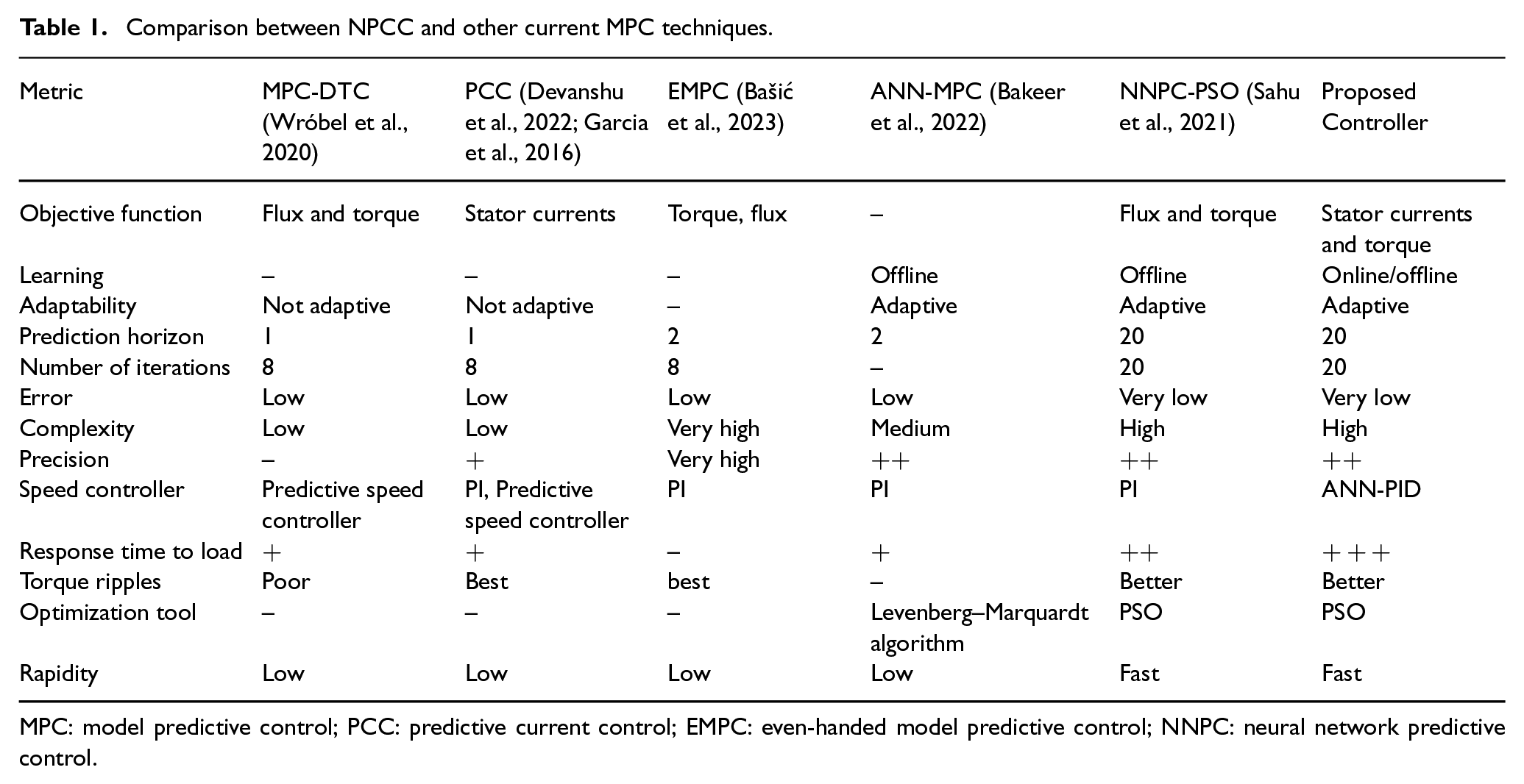
MPC: model predictive control; PCC: predictive current control; EMPC: even-handed model predictive control; NNPC: neural network predictive control.
Table 1 highlights the superiority and contributions of the proposed controller compared to various other MPC techniques, including model-based control (MPC-DTC, PCC, EMPC) and non-model-based control (ANN-MPC and NNPC-PSO). Compared to model-based controllers (MPC-DTC, PCC, EMPC), the proposed controller is superior due to its real-time adaptability and dual optimization of stator currents and torque, which optimizes electromagnetic torque ripple and transient performance, features that traditional model-based controllers lack. Compared to non-model-based controllers (ANN-MPC and NNPC-PSO), the proposed controller’s combination of adaptive speed control using real-time adaptive learning (ANN) and offline ANN predictor in NPC-PSO adaptive learning, along with advanced prediction and optimization techniques, results in better accuracy, faster response, and improved robustness. Torque and flux are controlled indirectly with optimized torque ripple, which is posed as an optimization problem solved by PSO. Optimization uses predictions over a 20-point horizon made by an ANN carefully selected by correlation matrix analysis. The paper is structured as follows: Section “ANN-PID speed controller” is the design of ANN-PID controller speed. Section “NPC controller design” is dedicated to the design of the NPC-PSO controller. The simulation results and robustness tests of the proposed controller are presented in section “Results and discussion.” This section also highlights the superiority of the proposed controller over an ANN and fuzzy-PI controller. The conclusion is presented in section “Conclusion.” Finally, the paper is concluded with a list of references.
ANN-PID speed controller
As shown in Figure 1, the ANN-PID architecture comprises two stages. The first stage is to identify the IM and estimate the speed using appropriate inputs. The second stage involves the adaptation of all the PI parameters using gradient descent algorithms (Chetouani et al., 2023; Kumar et al., 2014). The objectives of the speed controller using ANN-PID are as follows:
Speed control: To force the speed to follow a reference signal that evolves over a wide range of variations.
Adaptive design: To develop an adaptive version of the speed controller to ensure its robustness to variations in motor parameters and load torque.
Stage 1: ANN speed estimator
The primary objective of the first stage is to estimate the gain online
Inputs selection for ANN speed estimator
To identify and select the predominant inputs for the velocity estimator, a correlation analysis is essential. This analysis examines the relationship between the output of the ANN and its potential inputs (El Aoumari et al., 2023; Mahfoud et al., 2022). This requires a complete data set representing the state of the IM under various operating conditions. This includes variations in the reference speed across all four quadrants of the motor, as well as changes in the load torque in different ways across these quadrants, to enrich the data collection set. This data set can be efficiently constructed using a series of simulated IM tests. This protocol was extended to include both the estimator data and the predictor used in the NPC-PSO regulator. Consequently, the same data size was employed for the construction of the correlation matrix for both the ANN estimator and the ANN predictor. It is important to note that in the context of input identification for the ANN, reliance on simulated data alone is sufficient for the correlation study without the need for real-world data (Hassan et al., 2023). The data collection should comprehensively cover all state variables that define the characteristics of the IM. This includes, but is not limited to, variables such as direct and quadrature currents (
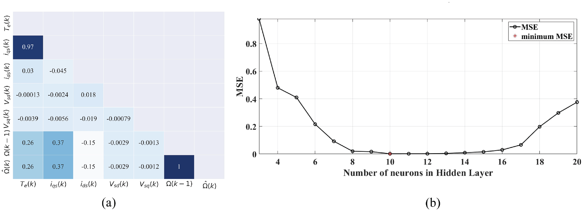
(a) Correlation matrix for speed estimator. (b) The evolution of MSE with respect to the number of neurons in hidden layer.
Compare the calculated
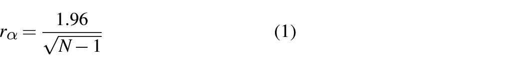
And the decision rule is

For our case,
ANN architecture
An architecture with multiple hidden layers and neurons can improve estimation accuracy, but often results in longer computation times. To avoid this problem, a design with a single hidden layer was chosen for the speed controller. The approach to determine the ideal number of neurons in the hidden layer started with a basic setup, initially with a minimum of three neurons, and gradually expanded to a more complex structure, up to a maximum of 20 neurons. During this process, the performance of the ANN was methodically evaluated (Chetouani et al., 2023; Mahfoud et al., 2022).
Figure 2(b) shows how the training error of the ANN varies with changes in the number of neurons in the hidden layer.
Gain computation
For speed estimation, a simple MLP architecture is used (10 neurons in the hidden layer (see Figure 2(b))). The output of the MLP architecture can be expressed mathematically as follows

where X is the vector input selected by the correlation matrix.
Stage 2: Law adaptation
This task is framed as an optimization problem with the primary goal of refining two objective functions: rotor speed estimation error

The tracking error is given by
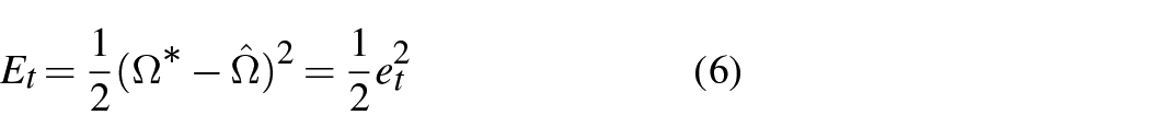
where
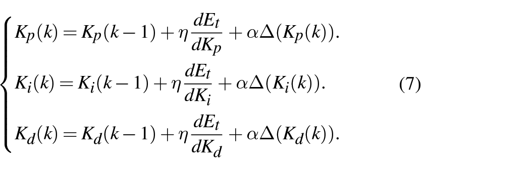
The adaptation law for
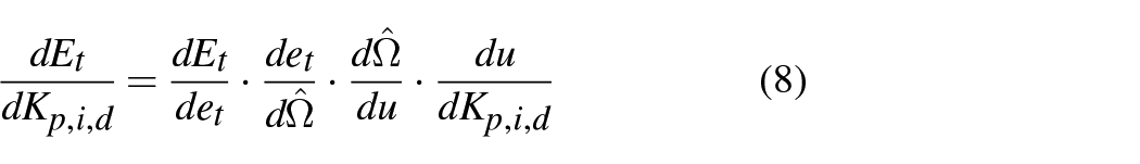
The derivatives
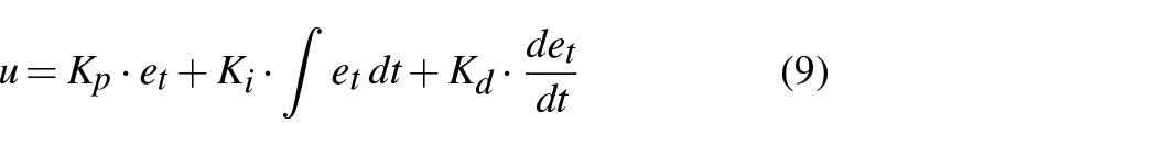
The control signal u, representing the electromagnetic torque, is defined as
Using equation (6), we obtain
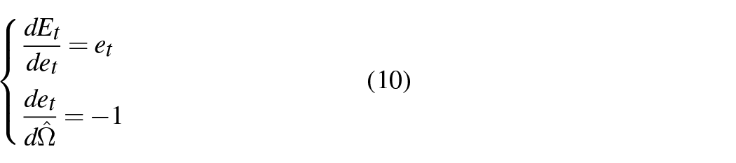
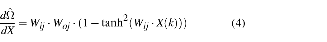
Applying equation (4), we find
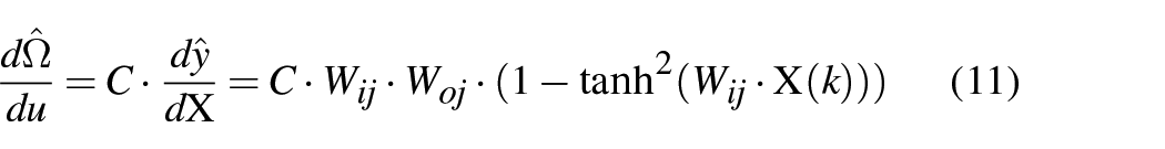
Here, C is a matrix corresponding in dimension to the input vector X, defined as
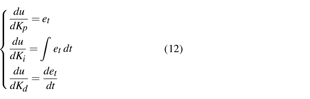
Using equation (9), we derive
The momentum term

where α represents the momentum coefficient.
Including equations (10)–(12) in equation (7), it becomes
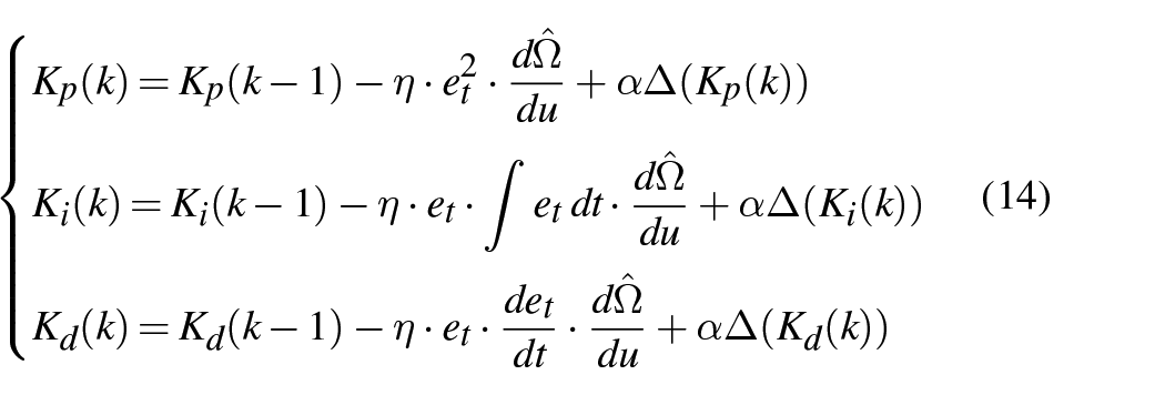
The methods for adjusting the weights and biases in the ANN estimator, employing gradient descent with a momentum term, are defined as follows
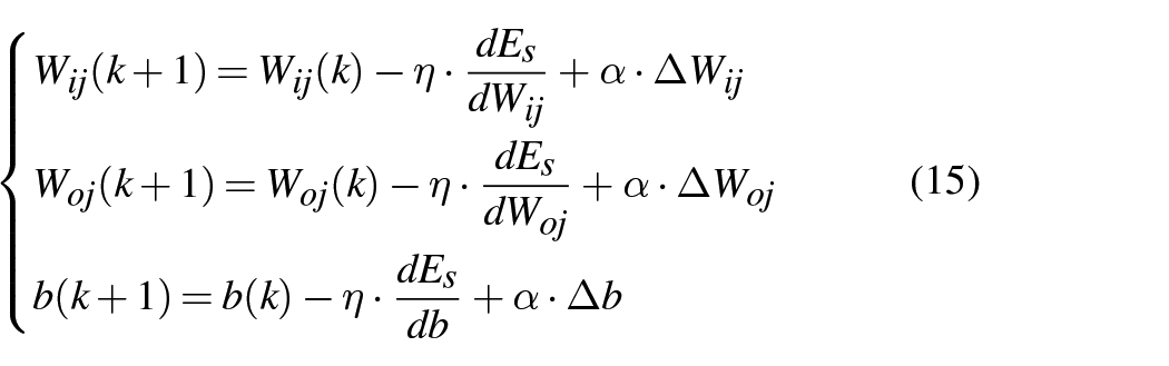
where
The derivatives
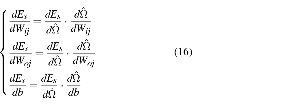
Using equations (3), (5), and (16), we derive
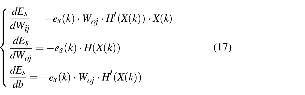
Substituting equation (17) into equation (15), we obtain
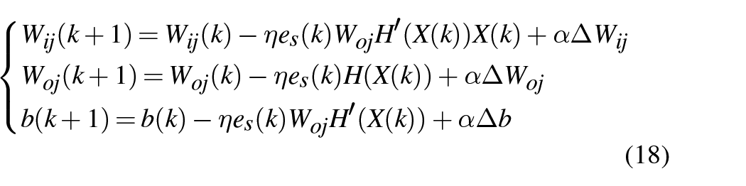
Here,
The factor α is the momentum coefficient that controls the contribution of past weight changes to the current update. It is usually set between 0 and 1.
The term
By adding a portion of the previous update, the momentum term helps smooth out the updates. This can prevent the optimization process from getting stuck in local minima and can also help to navigate more efficiently through flat regions of the error surface (Chetouani et al., 2023; Taşören et al., 2020).
In addition, the momentum can have a stabilizing effect on the learning process, potentially leading to faster convergence.
NPC controller design
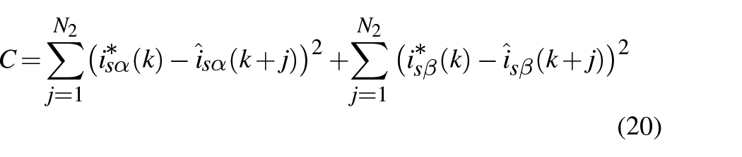
The NPC-PSO control method optimizes an objective function comprising two distinct components: current tracking errors and electromagnetic torque ripples. Additionally, the objective function is computed over a specific period using predicted IM current results. The particle swarm optimization (PSO) algorithm is employed to solve this optimization problem (Hassan et al., 2023). Figure 3 illustrates the working of the NPC-PSO controller. The objectives of the current loop using NPC-PSO are as follows
Torque and flux control: To control torque and flux indirectly by controlling the (α-β) components of the stator currents.
Optimal electromagnetic torque ripple: To ensure that the current controller maintains optimum electromagnetic torque ripple as required by various applications such as electric traction.
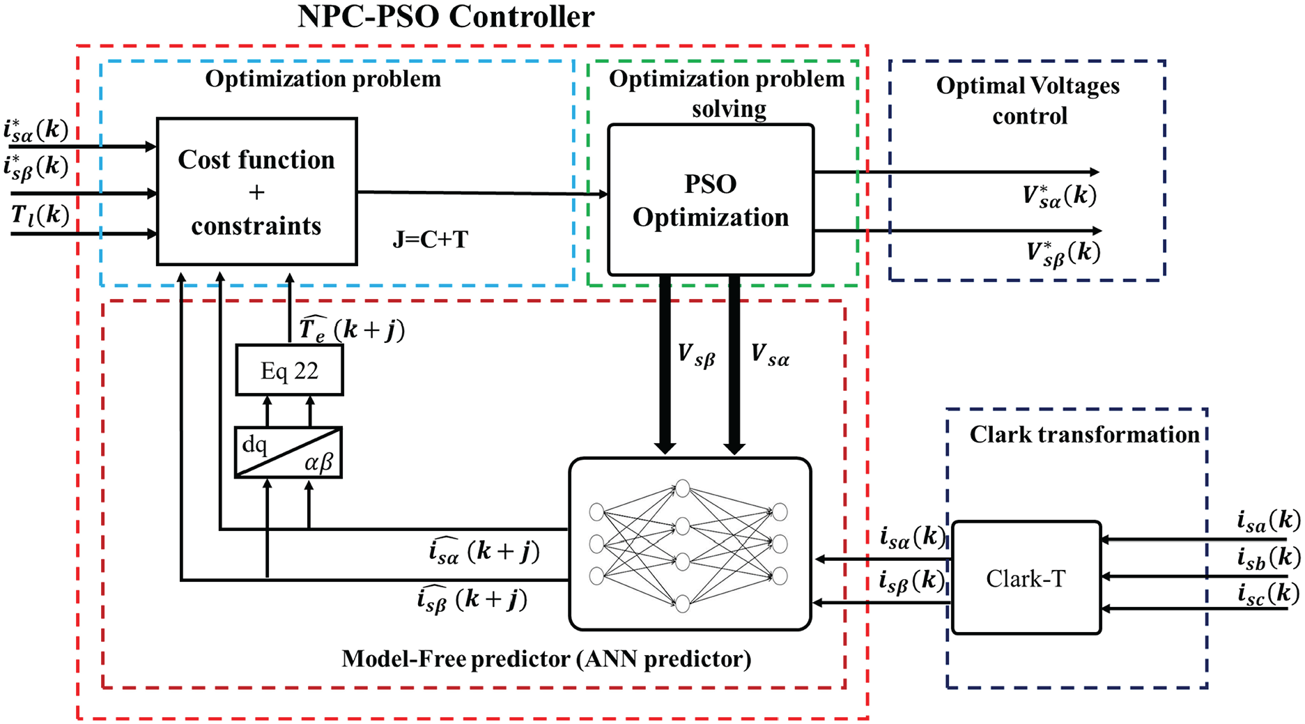
NPC-PSO controller architecture.
ANN predictor
To ensure the development of comprehensive learning data, it is crucial to consider all pertinent details related to the variable speed drive system’s various operating modes, including those in all four quadrants and with and without load torque application.
Preparing learning data (inputs/outputs)
Picking out the appropriate input variables can be tedious, but employing the correlation matrix allows for identifying the most suitable choices to achieve precise predictions. The results of the correlation are shown in Figure 4.
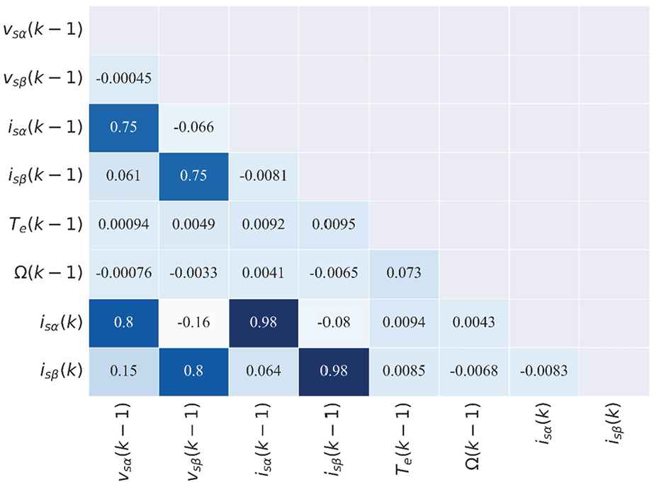
Correlation matrix between variables of IM.
Figure 4 shows the correlation between several variables. Each cell in the table represents the correlation between two variables. As indicated in Figure 4, we have two outputs,
Using the same approach in ANN estimator and using Equation 1, we can select the inputs predictor. The correlation matrix indicates a slight dependence of
Similarly,
From the correlation matrix analysis, we can infer that the prediction of the variables
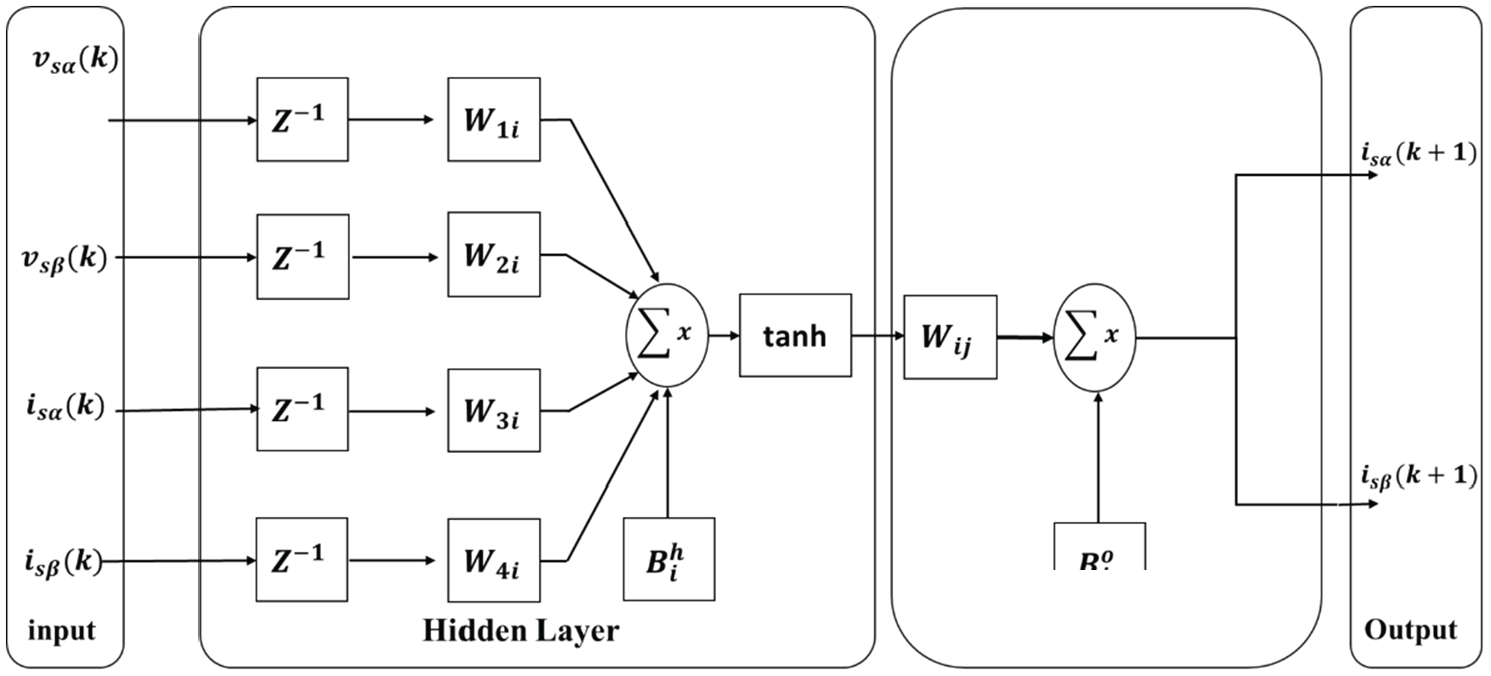
The ANN predictor architecture.
Selection of neural network topology
Upon completion of the training base preparation, 70% of the data is reserved for supervised learning of the network, while 15% is allocated for network validation. The remaining 15% of the data is set aside for the learning test. After selecting inputs used in the predictor, Figure 6 shows the strategy for building a j-step predictor using a cascade MLP predictor. The initial step involves constructing a predictor with a 20-point forecasting horizon (Figure 4). The j step prediction horizon in an ANN predictor is a critical feature that allows the network to predict future system states using historical control inputs and outputs. This horizon, denoted by j, determines the range of the ANN’s projections into the future, thereby informing the controller’s optimization process for current actions in anticipation of those outcomes. The chosen value of j, representing the depth of prediction, directly affects the controller’s ability to anticipate disturbances and maintain the desired system trajectory (Sahu et al., 2021). As a result, the construction of the initial MLP predictor is sufficient.
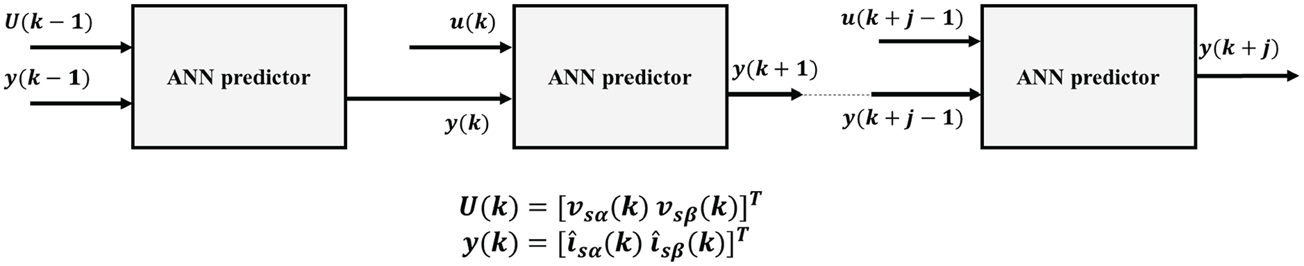
j-step ANN prediction architecture
To complete the design of the predictor, it is crucial to consider its internal architecture, in particular, the number of neurons, the hidden layers, and the activation function to be used. However, running tests is the most important aspect to determine the appropriate number of neurons for the hidden layer. The architecture used is shown in Figure 5. This architecture is justified by its simplicity and reduced prediction time, which is important because there is a significant computational load in the NPCC-PSO (neural predictive current control-particle swarm optimization) control. In addition, this cascading architecture is used to achieve a reasonable mean square error (MSE) (Chetouani et al., 2023; Hassan et al., 2023). To complete the design of the predictor, it is crucial to consider its internal architecture, particularly the number of neurons, the hidden layers, and the activation function to be used. However, tests are the most crucial aspect of determining the appropriate number of neurons (like ANN estimator) to use in the hidden layer. The architecture used For ANN is given in Figure 5. This architecture is justified by its simplicity and reduced prediction time because we have a calculation load in the NPCC-PSO control. In addition, we use this cascading architecture with a reasonable MSE.
The LM backpropagation training technique adjusts the weights and biases in all connecting links to minimize the difference between the output and the target output for different data. This study used a tan-sigmoidal function in the hidden layer and a linear transfer function in the output layer.
Considered objective function and constraints
After building a neuronal predictor to forecast the
The first term aims to enhance the dynamic performance of the IM by assessing the quadratic error between the reference currents
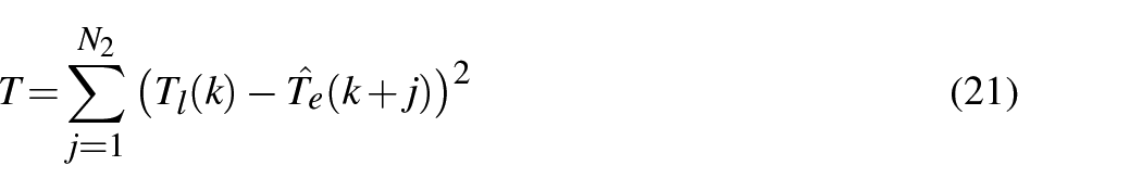
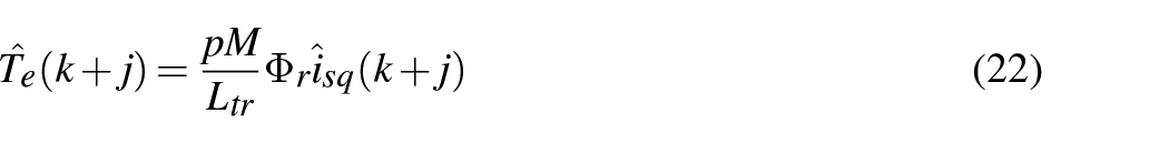
The second term aims to minimize the ripples by computing the electromagnetic and load torque difference for the mechanical stability of IM.
The objective function is given by

where
with

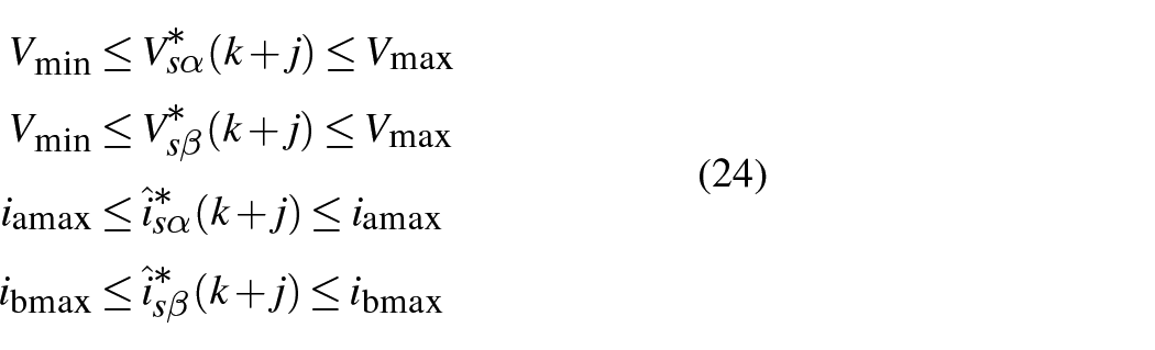
Corresponding to the specified constraints
Optimization problem-solving
PSO is selected for its capability to optimize complex systems and its proficiency in handling nonlinear functions and multiple variables (Hassan et al., 2023). This makes it an exemplary choice for NPCC of IM (Hassan et al., 2023). The use of PSO is justified by the following points:
These equations determine their direction: the movement of the particles is directed toward the particle that holds the best global reference control.

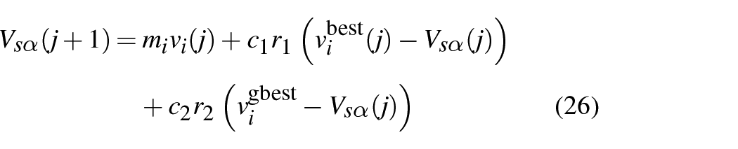

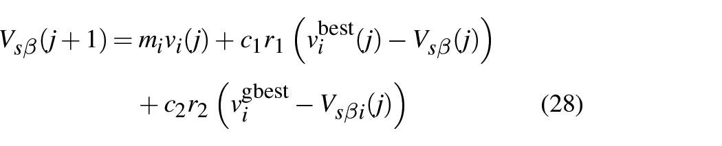
where
Results and discussion
This section covers the simulation studies and robustness tests of the proposed hybrid control strategy using an ANN-PID controller for the outer speed loop and an NPC-PSO for the inner current loop, applied to an induction drive. The effectiveness of the proposed control scheme is demonstrated through various performance metrics, including accuracy, torque ripple, speed response, and robustness to parameter variations due to thermal effect and magnetic saturation. The simulation environment, developed using MATLAB/Simulink, models the dynamics of the IM and implements the proposed control strategy.
Simulation protocol
In order to prove the performance of the proposed controller, the primary reference signal in the simulation was the rotor speed reference, which provided a basis for evaluating the performance of the controller under different conditions.
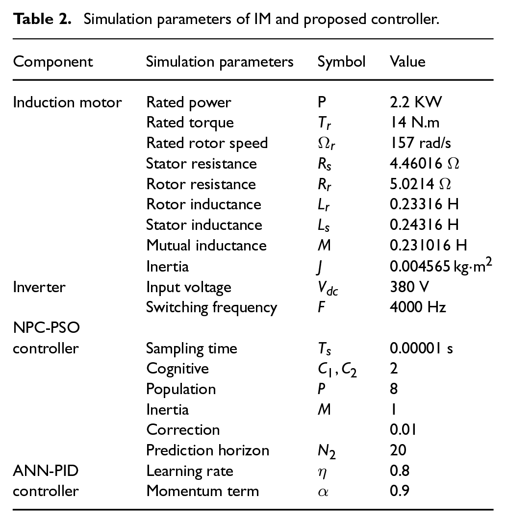
The specific parameters used in the simulation are listed in Table 2, including motor parameters and proposed controller parameters. The simulation protocol used to test the speed tracking performance is similar to those used in many applications, such as electric vehicles. As shown in Figure 7(a), the rotor speed reference signal has large variations over the interval [–140 rd/s, 180 rd/s]. More precisely, for the duration [3.8 seconds, 6 seconds], this reference is chosen higher than the nominal rotor speed (157 rd/s) to evaluate the proposed controller under weakening flux conditions. In addition, random variations of motor load and rotor inductance were introduced to test the robustness of the controller under realistic conditions characterized by large load variations and motor parameter variations after magnetic saturation. As shown in Figure 7(b), the IM load torque evolves randomly with a sampling interval of 0.5 seconds. To test the robustness of the presented controllers, variations of different motor parameters were performed. In particular, to simulate the thermal effect on the motor behavior, variations in the rotor resistance were introduced according to Figure 7(c). In addition, to account for the effects of magnetic saturation, variations in the rotor inductance were considered as shown in Figure 7(d). These perturbations, introduced throughout the simulation tests, aim to consider a set of realistic scenarios, providing more rigorous and relevant evaluation tests to allow a correct and reliable assessment of the proposed controllers. By subjecting the control system to these rigorous tests, the robustness and adaptability of the proposed hybrid control strategy have been thoroughly evaluated.
Simulation parameters of IM and proposed controller.
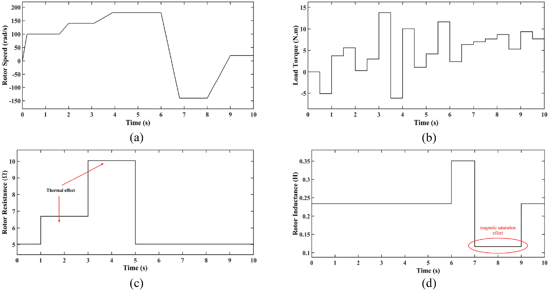
Protocol simulation. (a) Rotor speed reference signal (rad/s), (b) load torque (N.m), (c) rotor resistance variation
Proposed controller validation
Based on the described simulation protocol, this section aims to present the performance of the proposed controller. Several metrics are considered to evaluate the accuracy of rotor speed, stator flux, and current tracking, including root mean square error (RMSE)and normalized RMSE (NRMSE).In addition, total harmonic distortion (THD), electromagnetic ripple, and rise time are also analyzed to complete the performance evaluation of the developed control strategy.
Figure 8(a) presents the tracking performance for rotor speed that can be divided into four zones:
Zone 1: where the rotor speed reference remains lower than the nominal speed value [0s 4s]. Despite the load torque variations (see Figure 7(a)), the proposed controller exhibits excellent rotor speed tracking performance (with an error of 0.2 rad/s). More precisely, at
Zone 2: Where the rotor speed reference exceeds the rated speed value [3s 6s], as shown in Figure 8(b), this enlarged view illustrates the effectiveness of the controller when the rotor speed exceeds the rated speed (157 rad/s). Despite significant variations in the load torque every 0.5 seconds as shown in Figure 7(b) and a 100% increase in the rotor resistance
Zone 3: Where the rotor speed is reversed (negative rotor speeds) in the interval [6s 8s], this period exhibits the following changes: a rapid transition from 180 to −140 rad/s in 0.8 seconds (see Figure 7(a)), magnetic saturation resulting in a change in rotor inductance (Figure 7(d)), and variations in load torque every 0.5 seconds (Figure 7(b)). The proposed controller handles these changes efficiently by keeping the rotor speed tracking this reference with minimal undershoots and overshoots with an error of 0.3 rad/s, demonstrating its robustness in handling negative speed transitions and disturbances.
Zone 4: When the rotor speed reference remains below the nominal speed value and at low speeds, the speed changes from −140 rad/s to a low positive speed of 50 rad/s, also with a change in torque load (Figure 7(b)) and rotor inductance (Figure 7(d)). This further demonstrates the robustness of the proposed hybrid controller in handling negative to positive speed transitions even at low speeds.
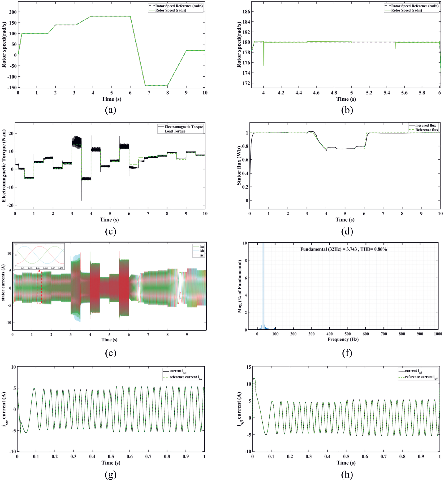
The proposed controller performances. (a) Rotor speed tracking performance (rad/s). (b) The zoom-in for rotor speed in [4 6] seconds. (c) Torque tracking performance. (d) Stator flux tracking performance. (e) The stator current for the tree phases. (f) THD for
Overall, the proposed controller excels in maintaining rotor speed accuracy and stability even under significant disturbances from load torque variations and changes in rotor inductance and resistance. The ability of the controller to quickly adapt and maintain stable operation under these varying conditions confirms its robustness and efficiency. Figure 8(c) shows the tracking of the electromagnetic torque compared to the load torque (Figure 7(b)). The proposed controller effectively follows the load torque. However, when the rotor resistance increases by 100% at
The satisfactory tracking current performance provided by the proposed controller results in favorable THD levels in the stator current, as shown in Figure 8(e). The stator currents
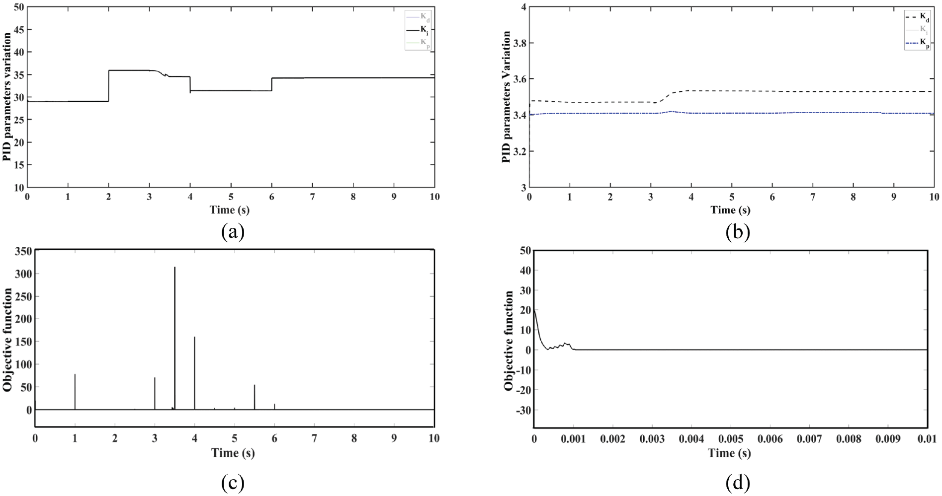
The performances of ANN-PID and NPC-PSO controllers. (a) PID parameters variation. (b) The zoom-in for
Figure 9(c) shows the evolution of the objective function over time. It is clear that the objective function tends to 0, but shows some peaks at different times, particularly around 1, 3, 4, and 5 seconds. These peaks are caused by changes in the load torque as well as variations in the rotor resistance (Rr) and rotor inductance (Lr) of the IM. However, the NPC-PSO quickly adapts and brings the objective function close to 0. In the zoomed-in view of the first 0.01 seconds shown in Figure 9(d) the objective function starts at a relatively high value around 20 and quickly drops to near zero. This rapid decrease indicates that the PSO algorithm effectively reduces the current tracking error and torque ripple almost immediately after initiation.
Comparative analysis
In this comparative study, the performance of the proposed controller was evaluated by comparing its performance with both the fuzzy-PI controller (Maghfiroh et al., 2023) and a contemporary ANN-based controller (Mahfoud et al., 2022). The dual comparison was performed under the simulation protocol, described in Figure 7.
Figure 10(a) shows the speed tracking results for the three controllers considered in this comparison. All three controllers show good speed tracking in the interval [2s 2.5s], with overshoots for the ANN controller, which is sensitive to changes in load torque every 0.5 seconds, the speed variation from 100 to 150 rad/s, and the increase in rotor resistance (Rr) by 25% of its value in the interval [2 3] s. However, at the time
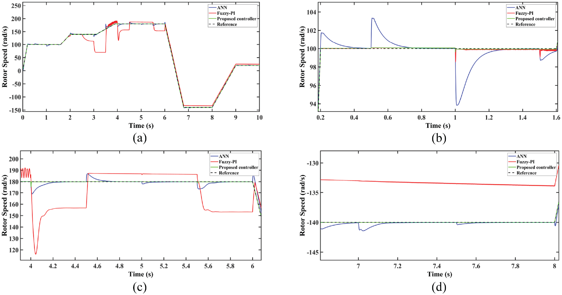
The rotor speed tracking performance for the considered controllers. (a) Rotor speed (rad/s). (b) The zoom-in for rotor speed in [0.2 1.6] s. (c) The zoom-in for rotor speed in [4 6] s. (d) The zoom-in for rotor speed in [6.8 8] s.
Figure 11(a) shows the electromagnetic torque tracking to the load torque. The fuzzy-PI controller shows poor performance in terms of accuracy. It has significant ripples and noticeable deviations from the load torque, especially around 3 and 4 seconds. The ANN controller shows better performance compared to the fuzzy-PI, but still shows significant ripple. Although its accuracy is improved, it remains sensitive to changes in load torque, with noticeable oscillations, especially visible around 4 seconds. The proposed controller shows the best accuracy among the three controllers. It follows the load torque very closely with minimal ripple. Even in the presence of load torque variations, the proposed controller maintains a stable and accurate response, showing superior robustness and ability to minimize ripple compared to other controllers. Figure 11(b) illustrates flux control responses by ANN, fuzzy-PI, and the proposed controller under protocol conditions where rotor speed exceeds its nominal value of 157 rad/s, leading to flux weakening. The proposed controller is more stable than other controllers.
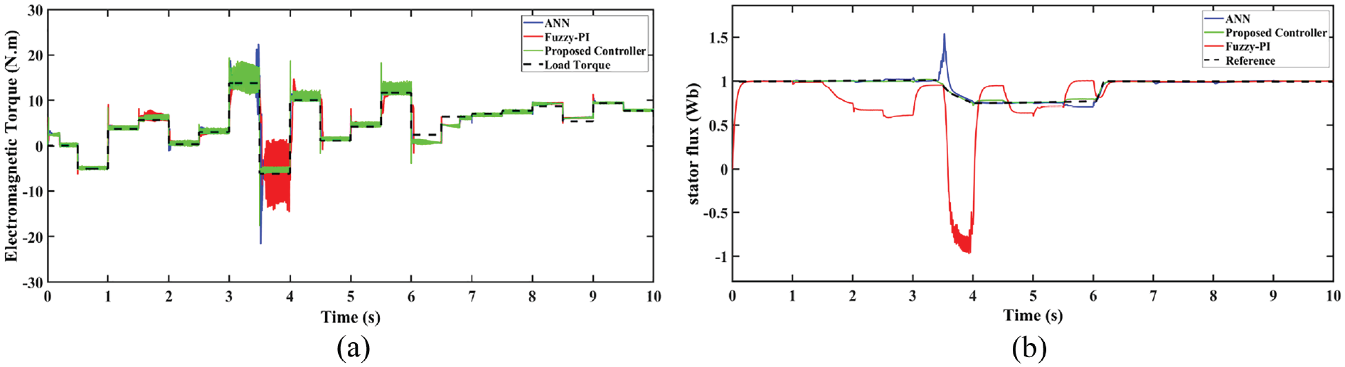
The comparison performances for considered controllers. (a) Torque tracking performance. (b) Stator flux tracking performance.
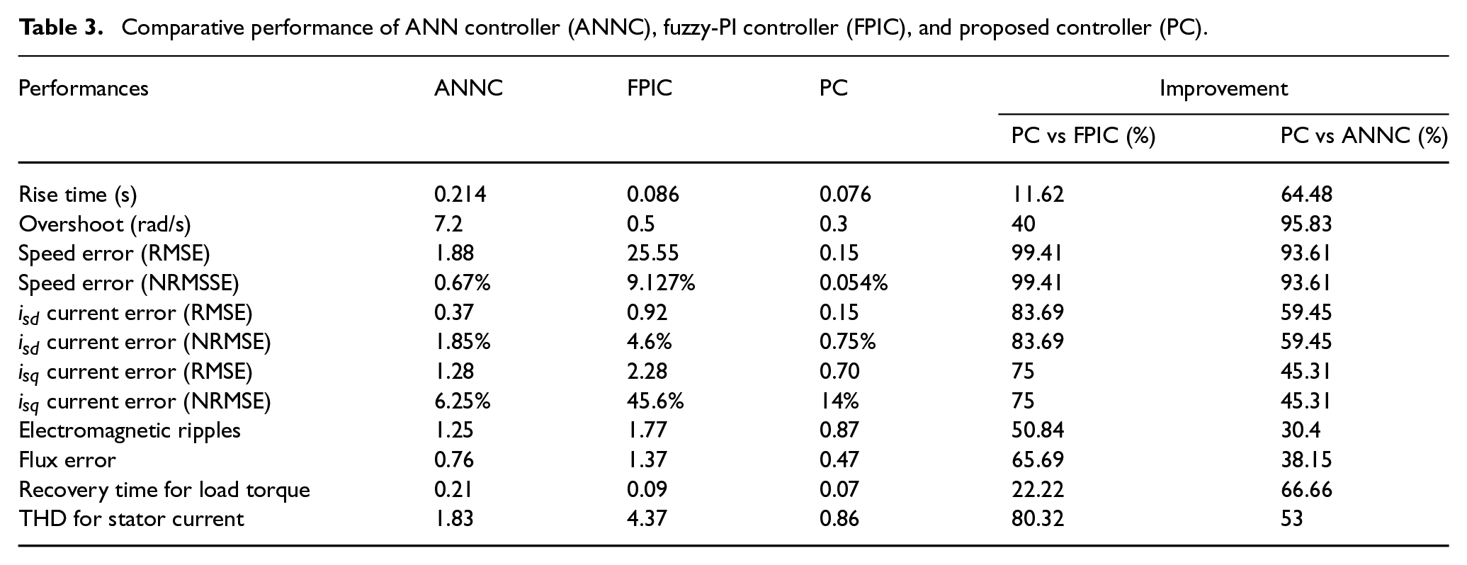
The numerical results of this comparison are summarized in Table 3. In terms of speed accuracy, the fuzzy-PI controller has an RMSE error of 25.55 and an NRMSE error of 9.127%, indicating significantly lower performance and less robustness. The ANN controller has an RMSE error of 1.88 and an NRMSE error of 0.67%, which shows that it is more accurate than the fuzzy-PI, but still less robust than the proposed controller. In contrast, the proposed controller shows exceptional accuracy with an RMSE error of 0.15 and NRMSE error of 0.054%, the lowest values among the three controllers, demonstrating not only superior ability to follow the speed reference with great accuracy, but also remarkable robustness in the face of variations in load torque and resistance and rotor inductance. Regarding the ripples of the electromagnetic torque, the ANN controller has a value of 1.25, while the fuzzy-PI controller has a value of 1.77, indicating larger ripples. The proposed controller again shows its superiority with ripples of 0.87, significantly reducing oscillations compared to other controllers. For the flow error, the ANN controller shows a value of 0.76, the fuzzy-PI controller shows a value of 1.37, and the proposed controller shows a value of 0.47. The proposed controller minimizes the flow error significantly compared to the other two controllers, with a remarkable improvement of 65.69% compared to fuzzy-PI and 38.15% compared to ANN controller. This table highlights the superior performance of the proposed controller in terms of speed accuracy, overshoot, undershoot, reduction of electromagnetic torque ripple and flux error, and stator current quality (THD).
Comparative performance of ANN controller (ANNC), fuzzy-PI controller (FPIC), and proposed controller (PC).
Conclusion
This paper introduces a hybrid control strategy for IFOC-IM, employing an adaptive ANN-PID for the external loop to dynamically tune PID parameters and an NPC-PSO for the current loop. The integration of NPCC and PSO enhances the robustness and dynamic performance of the IM by enabling more accurate current prediction through an ANN predictor. The hybrid control strategy, comprising NPC-PSO and ANN-PID, was compared with ANN and fuzzy-PI controllers and demonstrated using MATLAB/Simulink. The results indicate that the proposed control strategy exhibits superior performance, particularly in terms of robustness to variations in IM parameters. The hybrid control strategy demonstrated superior performance in speed tracking and minimized torque ripple, which may protect the motor from damage. Furthermore, the hybrid control strategy exhibits the shortest rise times, minimal overshoot and undershoot, and significantly lower THD in stator current. Lower values in error metrics such as RMSE and NRMSE in speed and current suggest more precise and reliable tracking, alongside the highest robustness and the fastest recovery time for load torque. These improvements confirm that the proposed controller offers enhanced stability, responsiveness, robustness, and efficiency, making it a superior choice for critical control applications.
Footnotes
Declaration of conflicting interests
The author(s) declared no potential conflicts of interest with respect to the research, authorship, and/or publication of this article.
Funding
The author(s) disclosed receipt of the following financial support for the research, authorship, and/or publication of this article: This work was supported by the Ministry of Higher Education, Scientific Research and Innovation, Morocco; the Digital Development Agency (DDA), Morocco; and the CNRST of Morocco (Alkhawarizmi/2020/39).