
Abstract
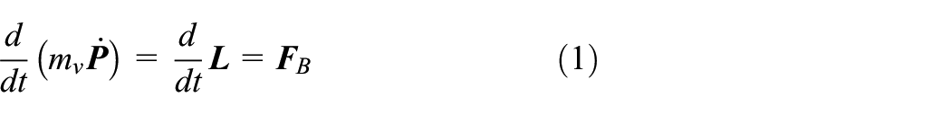
The trajectory tracking control of a quadrotor unmanned aerial vehicle is done in this paper in the presence of changes in the center of gravity due to the variations of a connected load mass and its position, external disturbances, and parametric uncertainties. At first, dynamic equations are obtained using Newton–Euler relations, and then a two-loop control architecture is designed for the trajectory tracking task. Backstepping and model predictive control are used in the inner and outer loops, respectively. An extended disturbance observer is adopted to improve disturbance rejection capabilities in both loops. For the six-degrees-of-freedom unmanned aerial vehicle, the effects of time-varying mass, which leads to the change in the moment of inertia and center of gravity of the system, together with external disturbances and parametric uncertainties are taken into account. It is possible to mount an arbitrary number of different point masses at arbitrary positions on the unmanned aerial vehicle. The proposed control scheme is evaluated using simulation in the presence of uncertainties and external disturbances. According to the simulation results, the developed control scheme can achieve stable flight under different conditions.
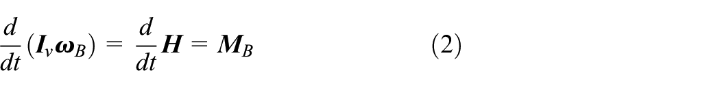
Keywords
Introduction
In recent years, with progress of technology and science, the application of unmanned aerial vehicles (UAVs) has developed greatly (Zhao et al., 2021). Quadrotors, as one of the UAVs with vertical-takeoff-and-landing capability, have attracted significant interest in applications including search-and-rescue operations (Alonso-Mora et al., 2012), videography, evaluating agricultural fields, fire detection, mapping, delivery, and use in inaccessible environments. The control of these vehicles is complicated since they are coupled and underactuated (ul Amin et al., 2019).
In real-world scenarios, the weight of a UAV or its load may change over time. This can have negative impacts on the UAV. Variation in the system’s center of gravity (CG) is one of the challenges of aerial grasping. Hence, the control system must be able to cope with the dynamic changes in the CG of the system (Ariyanto et al., 2016). The deviation of the vehicle CG can be caused, for example, by releasing a load or by transporting equipment mounted outside the geometric center. In addition, the installation of photo/videography devices and robotic manipulators can also shift the CG with respect to the geometric center of the UAV.
Different control methods have been utilized for the quadrotors, from linear control methods, such as proportional-integral-derivative (PID) (Bouabdallah et al., 2004; Li and Li, 2011), linear quadratic regulator (Reyes-Valeria et al., 2013), to nonlinear control methods, such as sliding mode control (SMC) (Davoudi Dehkordi and Danesh, 2022), and its variant methods (Danesh et al., 2023; Liang and Yang, 2023), backstepping (BS) (Mohammadi et al., 2018), feedback linearization (Jebelli et al., 2018; Palunko and Fierro, 2011). In Li et al. (2020), a hierarchical approach was used for quadrotor trajectory tracking in the presence of disturbances and parametric uncertainties. A disturbance observer-based BS was employed to control the outer loop of an outer–inner loop structure, and an adaptive nonsingular terminal sliding mode controller was designed for the inner loop to deal with parametric uncertainties. The attitude control of a quadrotor was performed by Wang and Zhao (2022) by adopting adaptive control which uses a linear active disturbance rejection control (LADRC) in the presence of external disturbances. The adaptive control was used to tune the parameters of the LADRC.
In the research by Xuan-Mung and Hong (2019), robust BS controllers were employed for trajectory tracking using a quadrotor. The extended state observer (ESO) was utilized to estimate both disturbances and system state variables. A nonlinear disturbance observer was used in conjunction with a BS controller (Tripathi et al., 2016) for position, altitude, and attitude regulation controls. Simulation results show the effectiveness of the composite controller. The works by Chen et al. (2016), Dong et al. (2014), and Moeini et al. (2022) used disturbance observers along with BS controllers to enhance trajectory tracking performance against disturbances and uncertainty. In the work of Derakhshan et al. (2024), disturbance observers were designed for a coaxial octorotor in conjunction with the model predictive control (MPC) approach to attenuate the effects of disturbances and time-varying mass. Moreover, in the work of Thanh et al. (2022), a controller with integration of an extended state/disturbance observer with a nominal BS controller was formed to improve attitude and position control performance.
The disturbance problem caused by changes in CG has been addressed in different ways. The study accomplished by Zhang et al. (2014) to control an aircraft involves a situation in which the system’s mass changes abruptly. Using linear matrix inequality-based nonlinear adaptive robust control as a control method for quadrotors delivering packages with unknown masses in a windy environment was another work done by Kun and Hwang, (2016). A study was conducted by Sadeghzadeh et al. (2012) to investigate load release operations on a quadrotor. The UAV was controlled using gain-scheduled PID and MPC. In Wu et al. (2019), the attitude of a quadrotor was controlled in the presence of time-varying mass by SMC theory.
A quadrotor with variable mass was controlled by nonsingular fast terminal SMC based on an adaptive integral BS control strategy (Zhao et al., 2021). However, the effect of time-varying mass on the system moment of inertia was not considered. Ariyanto et al. (2016) analyzed the effects of a change in the UAV CG when a payload was connected to the UAV. PID controllers were utilized to control the altitude and attitude of the system.
MPC uses a cost function that can consider the constraints imposed on the system to produce the desired control inputs. It is possible to incorporate the future trajectory in the cost function for path tracking, which can improve path tracking performance and disturbance rejection. Additionally, it will lead to smoother control signals (Mayne et al., 2000). MPC is considered a relatively practical method for linear and slow systems such as industrial processes (Mayne, 2014). However, with advances in numerical capabilities, this method is also applicable to nonlinear processes such as aerospace and robotic systems (Zhou et al., 2019).
In the research by Ma et al., (2016), the use of active disturbance rejection and predictive control techniques was explored for trajectory tracking of a quadrotor UAV in the presence of disturbances. To estimate existing disturbances, the predictive controller utilizes an ESO. Active disturbance rejection control and MPC were used to control rotational and translational movements, respectively. Additionally, the study by Wang et al. (2020) used a predictive control method to stabilize quadrotor attitude dynamics with a payload on the UAV. In the study by Urbina-Brito et al. (2021), an MPC was proposed for a quadrotor with a hanging load, in which the controller considers the dynamics of the suspended load, and the model is expressed as an input-affine system to design the controller.
The review of literature shows that many works conducted on load transfer using a quadrotor have merely investigated its attitude control and the moment of inertia changes have not been taken into account. Furthermore, in the majority of the previous studies, the system was either linearized around certain operating points or small angles assumption was used. Therefore, controlling the overall dynamics of the system in the presence of external disturbances and uncertainties can be challenging.
Although MPC is known as a powerful control method, as shown in the simulations, this method is sensitive to uncertainties in the model and model mismatches. Moreover, BS control is not robust to disturbances. Hence, in this research, a robust approach is developed based on a combination of MPC, BS, and an extended disturbance observer (EDO) to improve the performance of the system in disturbance rejection. The main contributions of the present work can be summarized as follows:
An EDO is designed to estimate various disturbances across all degrees of freedom (DOF). These disturbances are compensated in advance to increase the robustness of the UAV. Accurate dynamic modeling is presented in six degrees of freedom (DOF). To bring the conditions closer to the real world, the effects of variation in mass, moment of inertia, and CG on the overall dynamics are considered along with disturbances and uncertainties. It is also possible to mount an arbitrary number of different point masses at arbitrary positions on the UAV. A two-loop control structure is proposed using MPC with final state cost and BS control methods enhanced by EDO without knowing the upper bound of disturbances. Small angle simplification is not used in the control design process and robust trajectory tracking is achieved in the presence of uncertainties, CG changes, and external disturbances.
The remainder of this paper is organized as follows: In Section “Dynamic model of quadrotor,” the dynamic model of the quadrotor system is derived considering mass and CG changes. In Section “Control design based on disturbance observer,” a disturbance observer is designed and the proposed control scheme including translational and rotational controllers is developed. Simulation results are given in Section “Simulation results” to evaluate the designed control scheme. Finally, conclusions are given in Section “Conclusion.”
Dynamic model of quadrotor
The structure of a quadrotor is shown in Figure 1, in which
where

Body and inertial coordinate systems of the quadrotor with load.
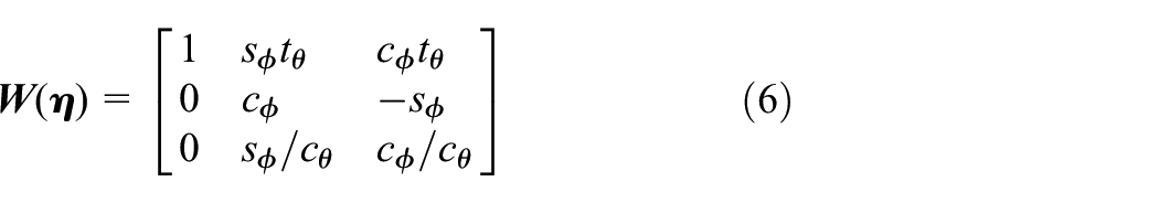
The relation between linear velocities in the body frame

Three consecutive rotations around the main axes can be performed to obtain the angular position vector
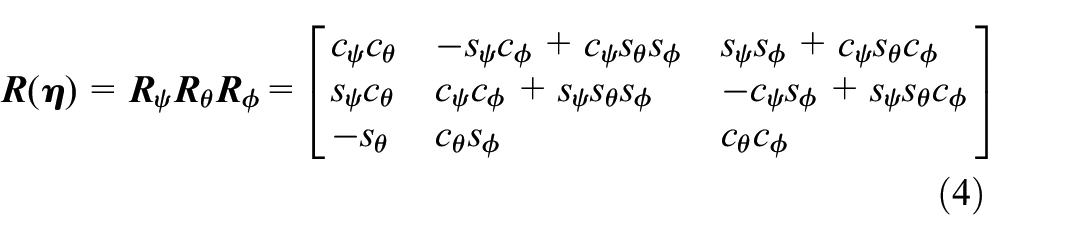
where

where
where

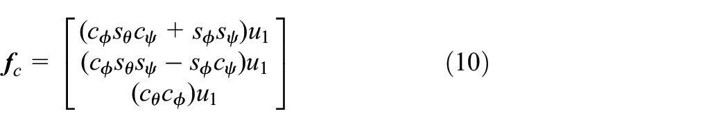
The resulting external force in the inertial frame is
where

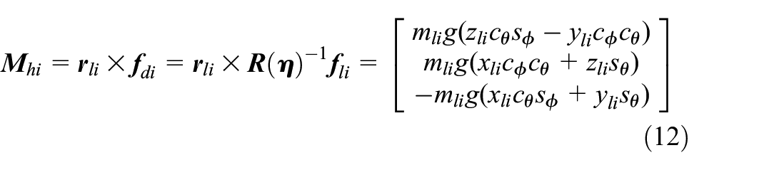
The total external torque is
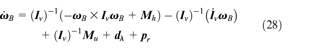
where
where
where
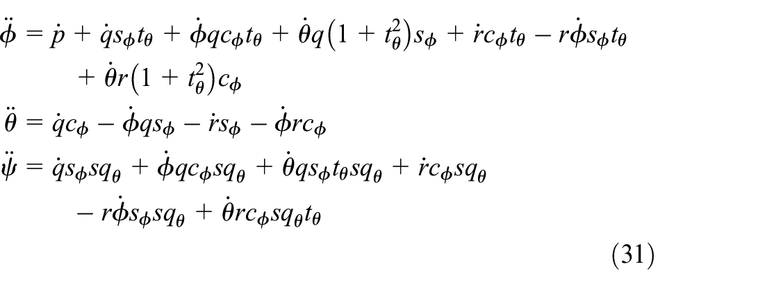
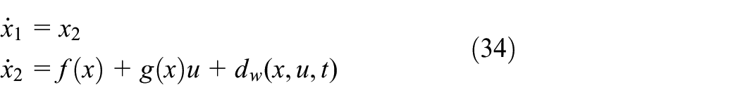
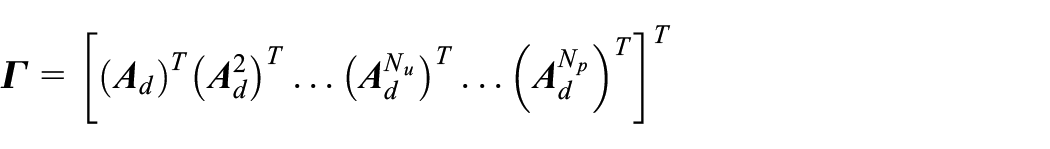
The translational and rotational dynamics can be rewritten in the following form:


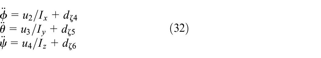
In Figure 1, a general connection of a load to the UAV is shown.
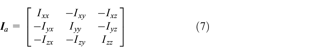
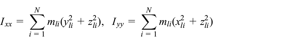
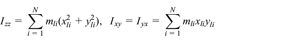
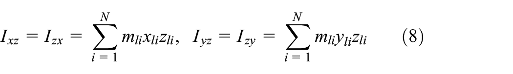
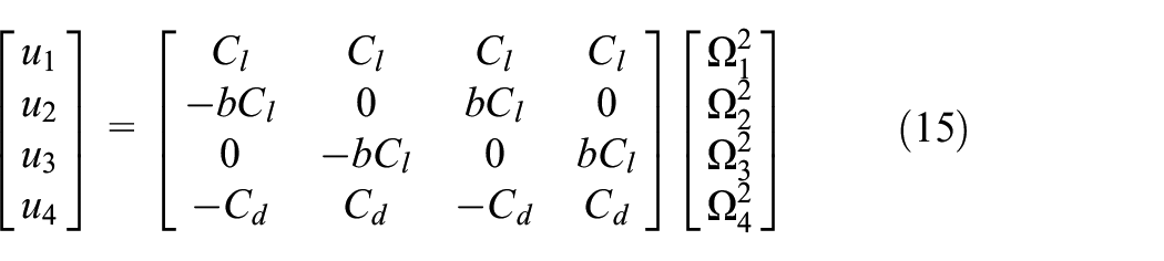
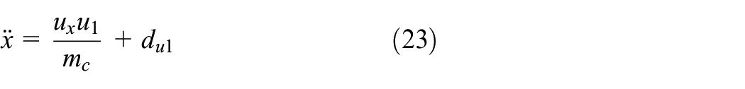
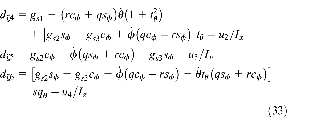
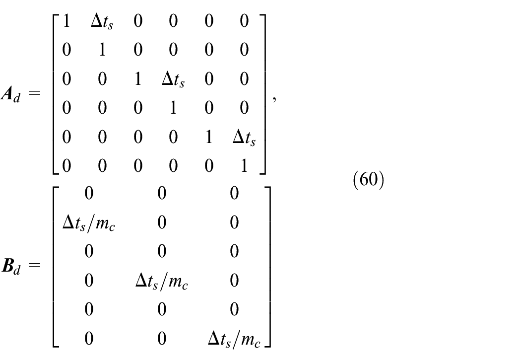
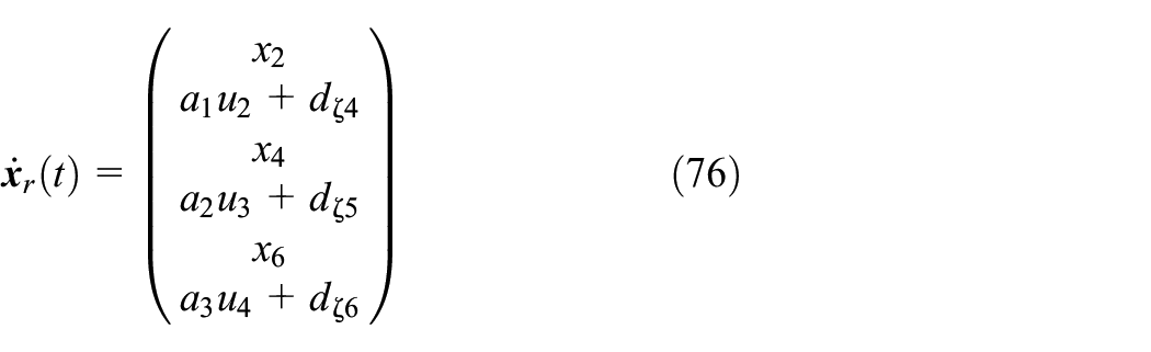
Rewriting (16) as a set of equations, (18) is obtained that considers the effects of time-varying mass and moment of inertia. Finally, the dynamic equations of the UAV can be given as
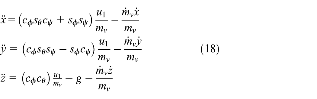

Taking (18) into account, we have
where
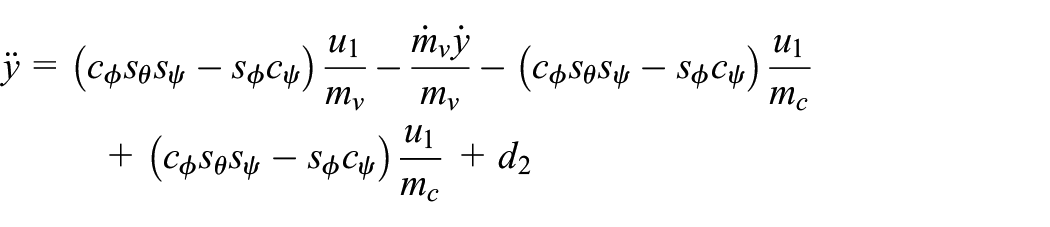
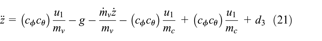
Define
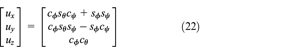
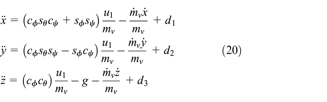
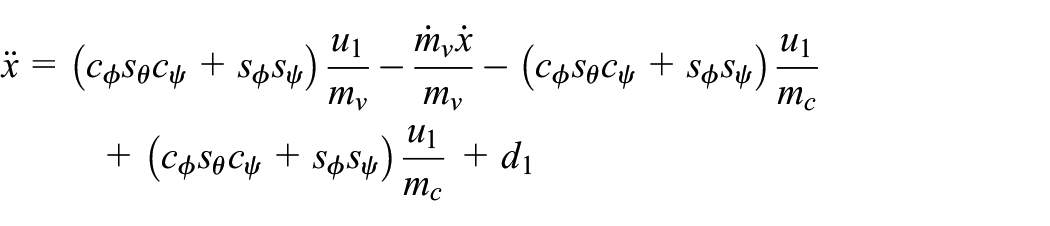
The terms that cause uncertainty can be summed up in the lumped disturbance term. Therefore, the translational dynamics can be rewritten as
where
New disturbance term
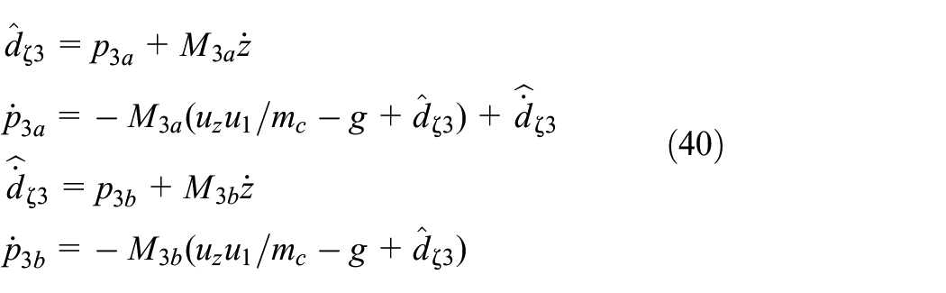
These lumped disturbances are expressed in a compact form as
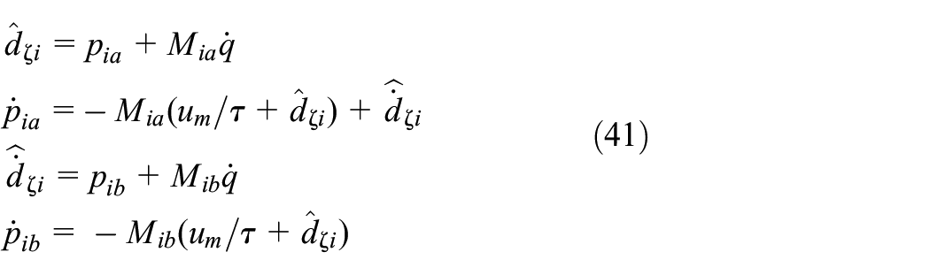
where

where

where it can be expressed as
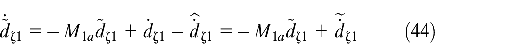
where
where
Control design based on disturbance observer
A disturbance estimation approach is employed to improve the performance of the designed controllers. After estimating the overall system disturbances, the control scheme uses them to make the system robust against lumped disturbances.
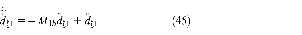
Disturbance observer design
Consider a second-order system defined as
where
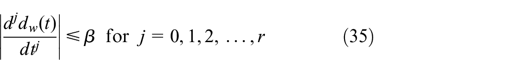
where
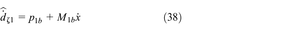
In this study, a second-order EDO (Ginoya et al., 2013) is used. Using (23) and (34), the disturbance observer relations for position

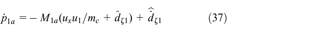

where
Similarly, the lumped disturbance estimation for position
To estimate the lumped disturbances of the attitude motions, the subscripts
where for
Stability analysis of the disturbance observer
Defining disturbance and disturbance derivative estimation errors as
From (23), (36), and (37), one can get
Subtracting both sides of the recent equation from
Similarly, from (23), (38), and (39), the following relation can be obtained:
Differentiating (44) and using (45) leads to
By recalling (44) and (45), finally, the dynamics of the estimation error can be written as

where
According to (47) and (48), by choosing

For any positive definite symmetric matrix

Defining the Lyapunov function candidate as

Differentiating
Finally, the estimation error norm is bounded as
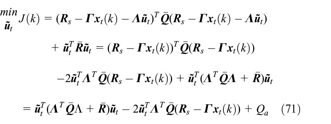
Controller design
To stabilize the UAV, a two-loop control structure is presented in which the system attitude dynamics are controlled in the inner loop, and the outer loop controls the system position variables. Figure 2 illustrates the trajectory tracking control structure.
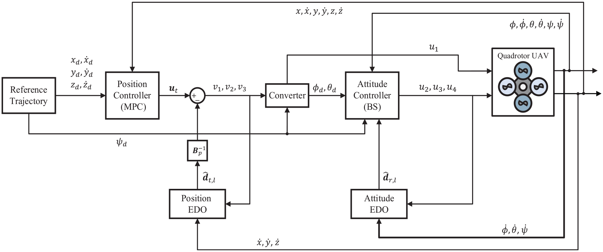
Block diagram of the proposed control structure for quadrotor.
Translational dynamics control
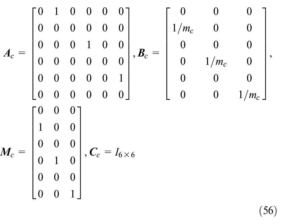
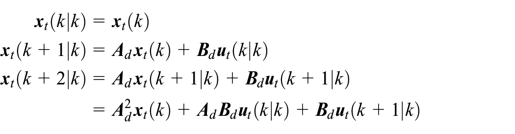
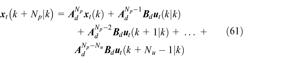
As a first step in designing the MPC of the translational subsystem, an internal model for prediction is derived. Defining


where


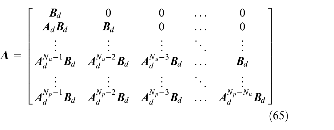
where the matrices
The lumped disturbances are not initially considered in the controller design process of the translational movements; however, later feedforward compensation is applied to counteract them. Therefore, (55) yields


Using the feedforward Euler method to discretize these equations produces


with

which results in
where
⋮
The system outputs along the prediction horizon can be obtained as


⋮

where
The predicted state vector
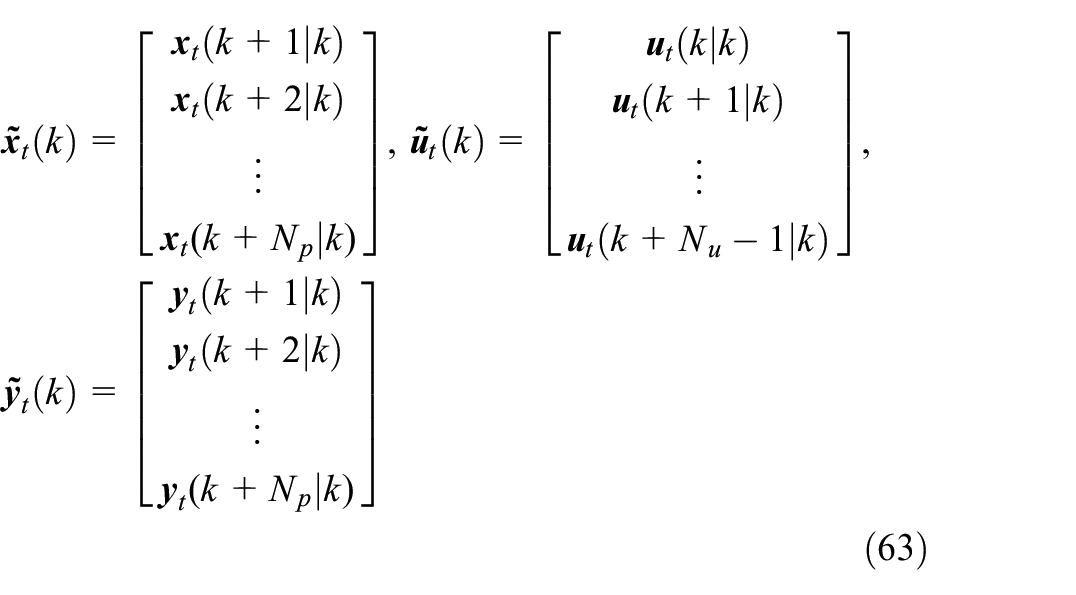
where


The matrices

As all state variables are controlled, hence,
The next step is to present a cost function that produces the control inputs at each time step using optimization. The reference trajectory vector at time step

where
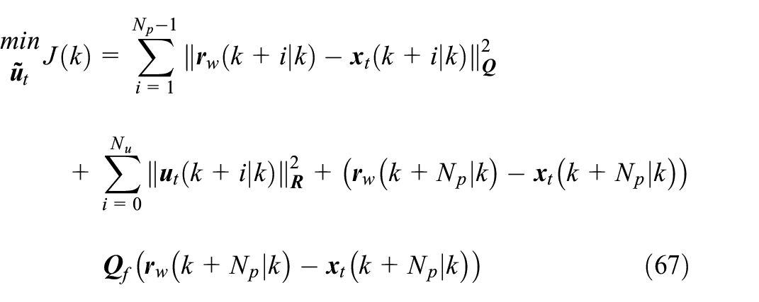
The first part of the above objective function is a penalty on the controlled variables, the second part penalizes the increase in the control inputs, and the last part describes the tracking final cost of tracking variables.
where
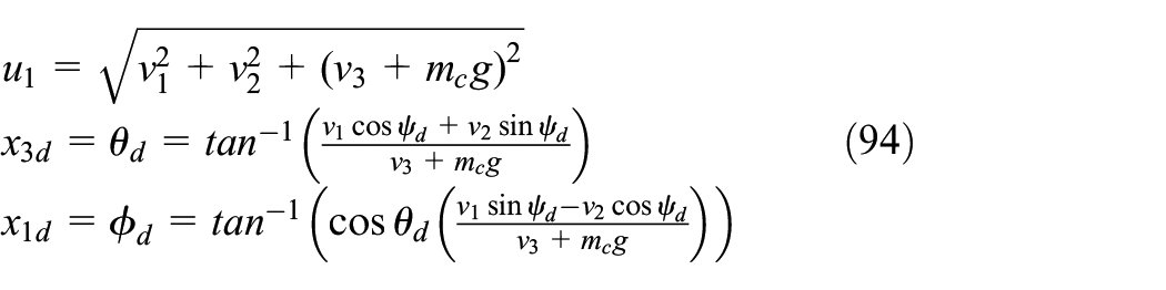
The reference signals are provided as follows:

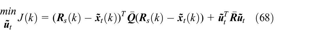
Substituting (64) into (68) yields
where
Finally, the optimal response is obtained as

Based on the receding horizon control law, only the first part of the optimal control sequence is used, while the rest is ignored. Therefore, the control law is rewritten as

where

In the following, the rotational-dynamic controller is designed, and the overall control strategy is developed.
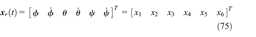
Rotational-dynamics control
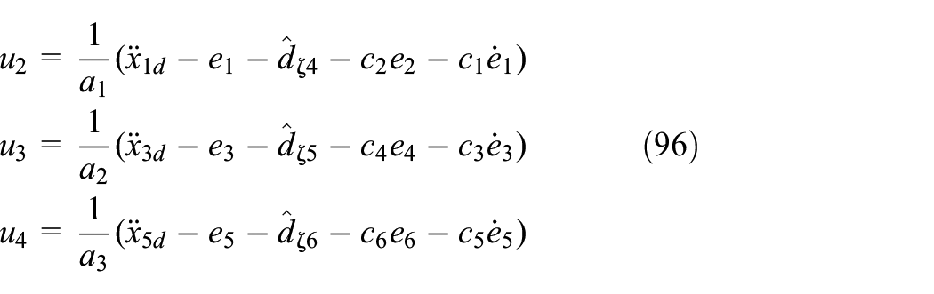
In this section, to control the rotational motion of the quadrotor, BS controllers are designed in the presence of uncertainties and disturbances. The rotational subsystem relationships in the presence of lumped disturbances can be written in the following state space form:
where


Defining the tracking error as

The Lyapunov function candidate is introduced as follows:
The derivative of this function is

Taking

Therefore,

To obtain the stability requirements, the next step is to consider the following augmented Lyapunov function:
Taking the time derivative of

Substituting

The stability condition can be considered as follows:

where
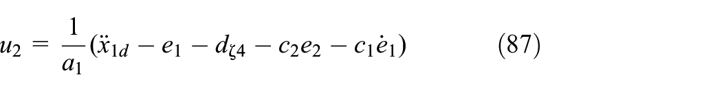
The pitch motion equations are given by
Similarly, the control input becomes
with

The yaw motion dynamics are given by
The control input is obtained as follows:
with

The values of
After obtaining the lumped disturbance estimation using the EDO, the control laws for the translational subsystem can be rewritten as
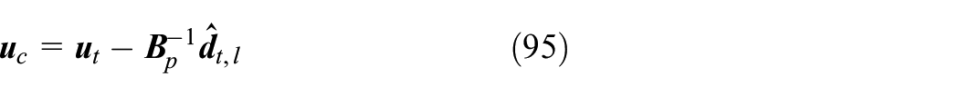
where
Simulation results
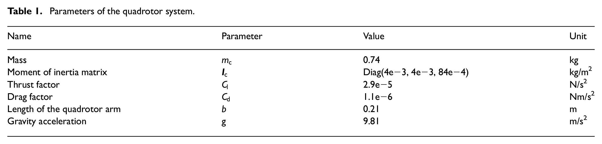
This section defines various scenarios to evaluate the performance of the presented controller. The effectiveness of the controller is tested with and without the disturbance rejection strategy. The designed controller is evaluated under conditions such as CG deviation, uncertainties, and external disturbances. The quadrotor parameters are given in Table 1. The parameters of the controllers were tuned as


Parameters of the quadrotor system.
The tuned parameters for the EDO are


Two scenarios are defined to investigate the performance of the proposed approach. In the first scenario, the proposed controller is evaluated under CG deviation caused by connecting a point mass with a time-varying position. A similar situation can occur when external loads such as robotic manipulators, cameras, and packages are rigidly attached to UAVs. All adjusting parameters of the reduced form controller are identical to the proposed controller. The second scenario compares the proposed method with integral backstepping (IBS) and PID controllers. It is worth noting that for the IBS, a tracking differentiator and first order command filter were used (Rashad et al., 2015). The parameters of the PID controllers were tuned using the MATLAB/Simulink optimization toolbox. The regulated parameters in both scenarios are identical.
Simulation example 1
The reference trajectory is defined as

The initial conditions are as

The applied disturbances in the first scenario are
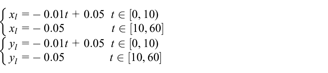
The simulation results in the first scenario are shown in Figures 3 to 5. The c1 case represents the case of CG changes, and the c2 case represents the condition of imposing external disturbances along with CG changes. The position tracking is shown in Figure 4(a). Clearly, the proposed approach outperforms MPC-BS without EDO. Generally, both methods follow the reference path and are stable. In addition, the performance of the proposed approach without considering CG variation and external disturbances (n.c.) can be observed. The tracking performance of BS controller in the inner loop is presented in Figure 4(b). It is observed that the attitude angles track their references generated by the proposed MPC and EDO in the outer loop. The references in the roll and pitch attitude angles curves are related to the case c2.
2D and 3D tracking view.
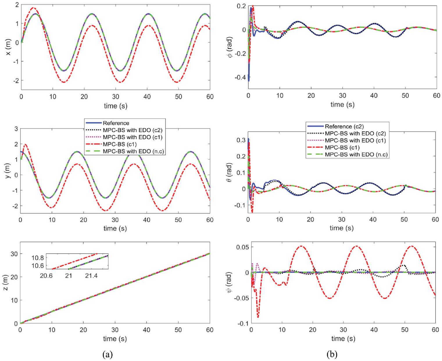
Trajectory tracking in the presence of external disturbances and CG changes: (a) position responses and (b) attitude responses.
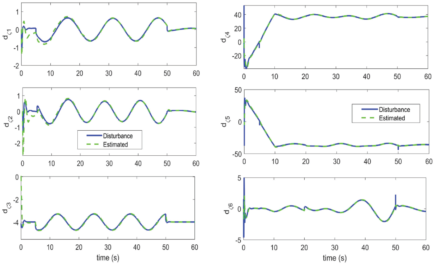
Lumped disturbances estimation.
The proposed method can successfully track the reference trajectories. The reason for this can be explained by the accuracy of the disturbance observer in estimating lumped disturbances and rejecting them actively. The performance of the EDO is shown in Figure 5. As seen, the observer estimates disturbances well. In Figure 6, variation in the control inputs is shown. It is observed that control inputs change to deal with load effects and external disturbances. At the beginning of the simulation in case (n.c.), the control inputs vary to move the UAV toward the desired reference. Once it reaches the desired reference path, the control inputs remain consistent. In the case of CG changes, the MPC-BS tracked path deviates from the reference (see Figure 4(a), red dashed curve), even though the system is still stable. According to Figures 3 and 4(a), the tracking performance of the MPC-BS controller is significantly better when the disturbance observer is used. Figure 7 shows variations in the connected mass position and moment of inertia. As a result of the variation in mass position, the moment of inertia is changed. Despite the CG changes, trajectory tracking using the designed controller is accurate in all directions.
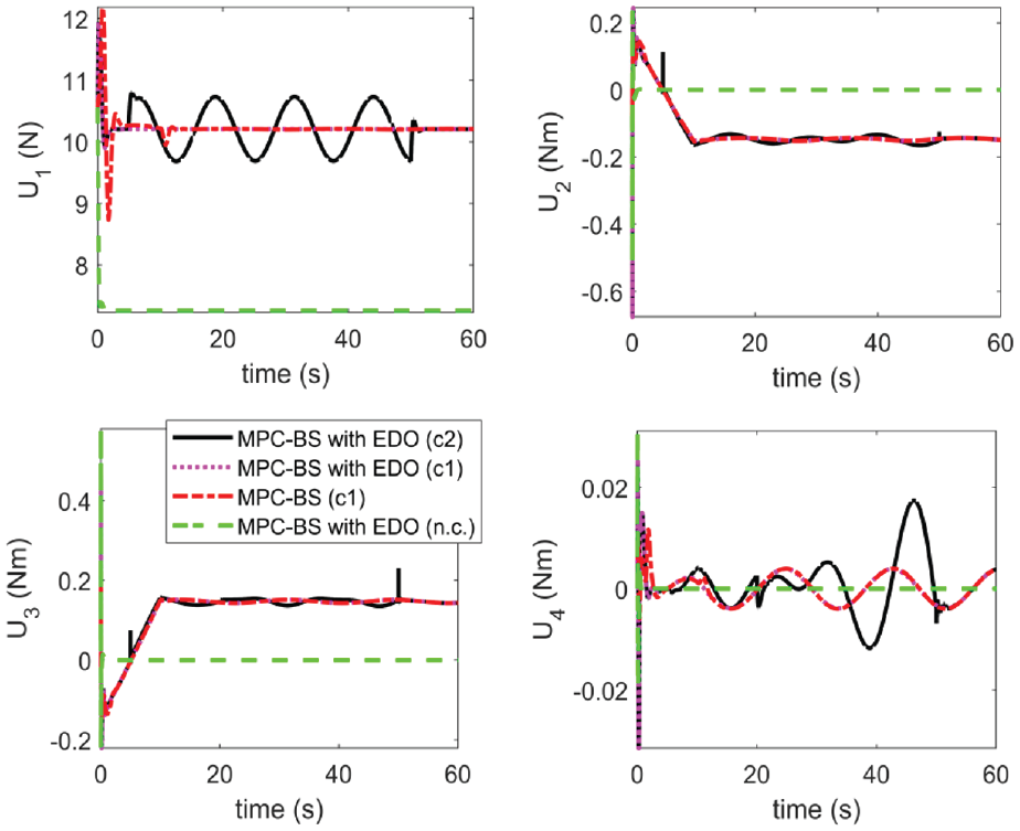
Control inputs.
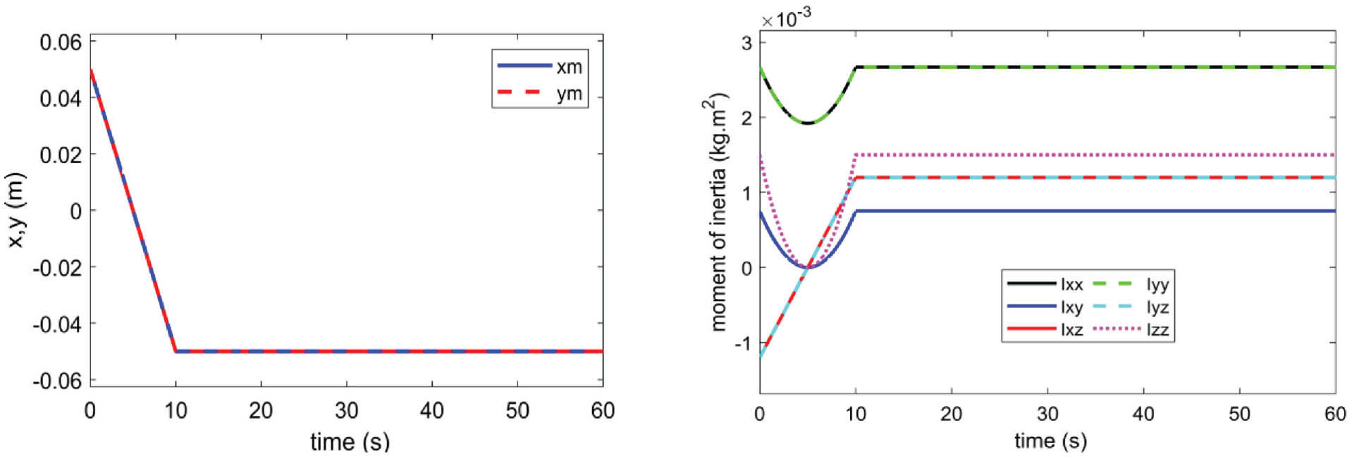
Mass position changes in
Simulation example 2
The reference trajectory is given in the following form:

The initial conditions of the translational and rotational subsystems are
Unmodeled dynamics and remaining uncertainties are assumed to always exist in the system and are as
The simulation results of this scenario are depicted in Figures 8 and 9. The 3D and 2D spaces of trajectory tracking are shown in Figure 8, where it is observed that the proposed strategy achieves superior performance under disturbances and uncertainties. Figure 9(a) shows tracking performance related to the position variables. The PID method fails to achieve accurate trajectory tracking. This is due to the effects of uncertainties and disturbances and the PID controller has no capability to reject them. The IBS and proposed methods can track the reference path accurately. According to the results, the proposed method outperforms the IBS method and deviates less from the reference path. Figure 9(b) illustrates attitude tracking performance. It can be seen that the attitude controller can follow the references generated by the presented approach. The IBS method has oscillations at the beginning of the motion and also while applying external disturbances at the
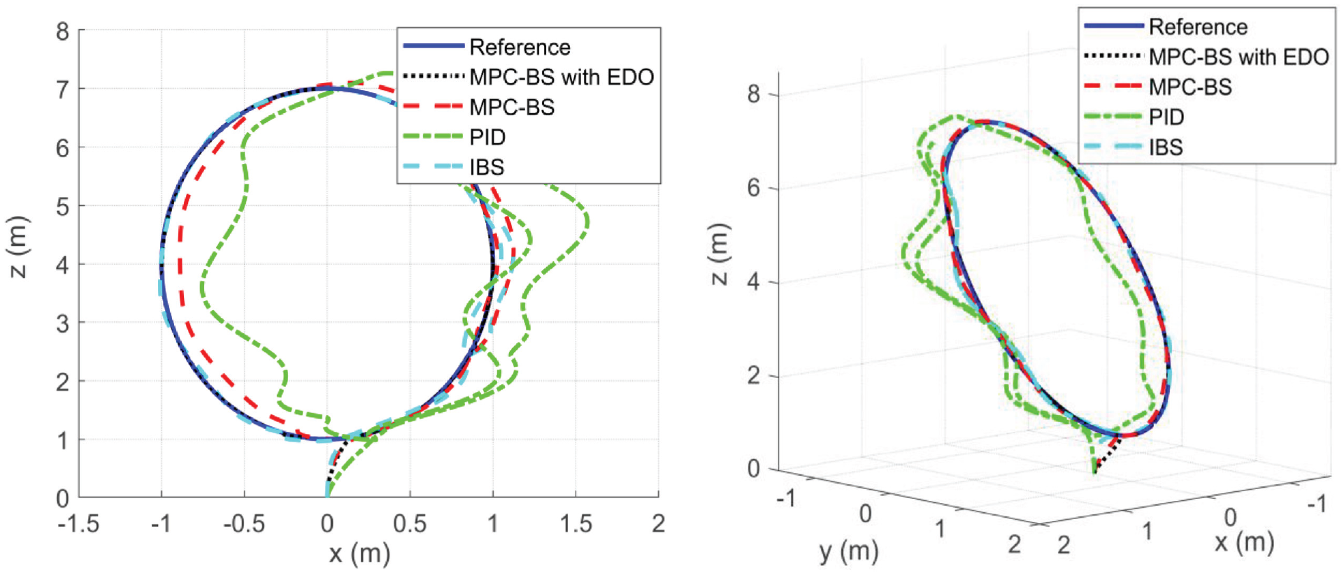
2D and 3D tracking view.
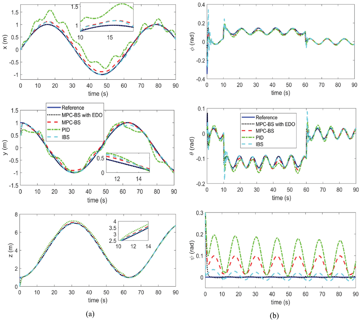
Tracking comparison between the proposed approach and other methods in the presence of uncertainties and external disturbances: (a) position responses and (b) attitude responses.
The proposed controller is capable of ensuring high performance attitude and position tracking for the quadrotor in the presence of uncertainties and disturbances. The results reveal that the proposed approach exhibits more accurate tracking performance compared with PID and IBS controllers under sustained and time-varying disturbances and uncertainties. According to the simulation results, the proposed approach can present a fast and robust response. Consequently, accurate trajectory tracking and robustness have been achieved against uncertainties, external disturbances, and CG changes.
Conclusion
This study presented an anti-disturbance control method that utilizes MPC and BS control combined with EDO to control a quadrotor with variation in the CG. A double-loop control structure was presented in which in the outer loop MPC stabilizes the position variables of the system, and in the inner loop BS was designed to control the attitude angles. The disturbances due to parametric uncertainties, unmodulated dynamics, external disturbances, and time-varying CG were considered across all DOF channels and estimated using the EDO. To increase the robustness of the UAV, these disturbances were compensated in advance. Moreover, it is possible to mount an arbitrary number of different point masses at arbitrary positions on the UAV. The simulations were carried out under time-varying disturbances and uncertainties. By comparing the presented approach with PID and IBS approaches, it can be seen that the presented approach achieves superior and smoother responses. From the simulation results, it can be concluded that the proposed approach offers significant robustness against different types of disturbances that the UAV may encounter in the real world.
Footnotes
Author contributions
All authors contributed to the study conception and design. Authors’ contributions are as follows: Material preparation: Reza Ebrahimpour Derakhshan. Writing the first draft of the manuscript: Reza Ebrahimpour Derakhshan. Review and editing: Mohammad Danesh and Reza Ebrahimpour Derakhshan. Supervision: Mohammad Danesh. Analysis and interpretation of results: Reza Ebrahimpour Derakhshan and Mohammad Danesh. All authors read and approved the final manuscript.
Declaration of conflicting interests
The author(s) declared no potential conflicts of interest with respect to the research, authorship, and/or publication of this article.
Funding
The author(s) received no financial support for the research, authorship, and/or publication of this article.
Data availability statement
The datasets generated or analyzed during the current study are not available publicly.