
Abstract
The tail-sitter aircraft’s transition control between the vertical take-off and landing mode (VTOL) and the level flight mode is plagued by drastic model changes, significantly complicating the flight control design during the transition phase. This paper presents an enhanced active disturbance rejection control (ADRC) technique using distributed dynamic pressure gain compensation for twin-engine flying wing-type tailstock aircraft as the specific research object. The observer model of the active disturbance rejection controller is improved according to the appropriately simplified model, and the different flight stages are unified into a single continuous flight mode in combination with the dynamic pressure detection gain adjustment. The problem of model change in the transition process is effectively solved. During the real flight test, the aircraft’s attitude change from 0° to 90° causes significant changes in the model parameters; however, the tail-sitter aircraft maintains a smooth transition control effect.
Introduction
The tail-sitter vertical takeoff and landing aircraft lack the intricate tilting mechanisms of tiltrotor systems, as well as the substantial power and aerodynamic drag associated with compound lift. Nonetheless, their distinctive tail-sitting vertical takeoff and landing, along with their hovering stance, enable them to execute airborne maneuvers with a minimal cross-sectional area. Its unique properties have tremendous application value in both the military and civilian sectors, and it offers a key research path in aircraft design and control (Qi et al., 2024; Sutariya et al., 2024). Two issues have arisen with tail-seat aircraft control during the transition phase: attitude singularity and control coupling resulting from significant angle shifts, as well as model alterations due to drastic aerodynamic fluctuations during the transition (Ang et al., 2015; Cheng et al., 2022). The mathematical challenge has evolved from the initial two sets of Euler angles and coordinate system switching to Quaternion-style global attitude representation and feedback control (Xu et al., 2019). The attitude singularity problem has been thoroughly solved, but the model change for the latter has always been the most critical and difficult challenge in flight control (Kuang et al., 2017).
Currently, there are methods offering global tracking controllers for flying wing vehicles, based on a dynamics model with online parameter estimates, using a cascade control structure to achieve coordinated flight, and experimentally proving the microcontroller platform. A new technique, based on a composite learning Model Predictive Control (MPC) framework, merges offline sparse modeling with online reinforcement learning to enable stable and efficient control of fan Unmanned Aerial Vehicles (UAVs) (Manzoor et al., 2025). Kong et al. (2022) propose an Reinforcement Learning - Active Disturbance Rejection Control (RL-ADRC) control method based on differential flat transform and reinforcement learning for the trajectory tracking problem of underdriven hovercraft, which significantly improves system robustness and adaptivity by optimizing the perturbation suppression strategy. Liu et al. (2023) propose a hierarchical anti-disturbance control architecture based on Recursive Least Squares and Extended State Observer combined with the Linear Quadratic Regulator optimization method to significantly improve the disturbance suppression and energy management performance of the spacecraft Attitude Control and Momentum Management system. Currently, some researchers have developed Vertical Take-Off and Landing Unmanned Aerial Vehicle (VTOL UAV) disturbance observer control and aeroelastic adaptive sliding mode strategies to improve wind-resistant hovering accuracy and suppress nonlinear vibration, respectively, as well as simulations to test their efficiency (Lyu et al., 2018; Mahmood and Kim, 2017).
This work presents a simpler angular motion model and an improved ADRC approach for tail-sitter aircraft. A distributed system adjusts the controller’s output gain to account for aerodynamic torque changes during transition. This reduces complexity, enhances transition flexibility, and enables high-angle attack transitions, offering greater versatility for VTOL fixed-wing aircraft. The paper is organized as follows. The next section illustrates the tail-sitter aircraft’s angular motion model and transition process features. “Active disturbance rejection controller with dynamic pressure gain compensation” section describes the angular velocity control approach for distributed dynamic pressure detection and compensation using an active disturbance rejection controller. “Simulation and flight test validation” section presents simulations of the angular velocity control software to verify the proper functioning of dynamic pressure compensation. Finally, the “Conclusion” section provides conclusions.
Angular motion model
During vertical takeoff and landing, aerodynamic properties, flight speed, and tension all fluctuate significantly, and these changes are irregular and nonlinear, making it impossible to explain them using a fixed and precise mathematical model. This offers significant hurdles to the aircraft’s dynamic modeling (Dilmi, 2022; Qiao et al., 2023). Detailed computational fluid dynamics simulations have been investigated. The nonlinear variations in characteristics are mostly due to airflow separation and changes in the distribution of the propeller slipstream on the wing (Liu et al., 2012; Zhou et al., 2017). The process of airflow separation and recovery may exhibit hysteresis depending on the direction of change. After a large angle of attack separates the airflow, a smaller angle of attack is required to recover the airflow, resulting in different parameter change trajectories in the forward and reverse transitions (Cakici and Leblebicioglu, 2016). Figure 1 depicts the hysteresis characteristics resulting from airflow separation. The aerodynamic properties typically correspond to lift coefficient, drag coefficient, and rolling damping, which vary with the flow conditions resulting from airflow separation.
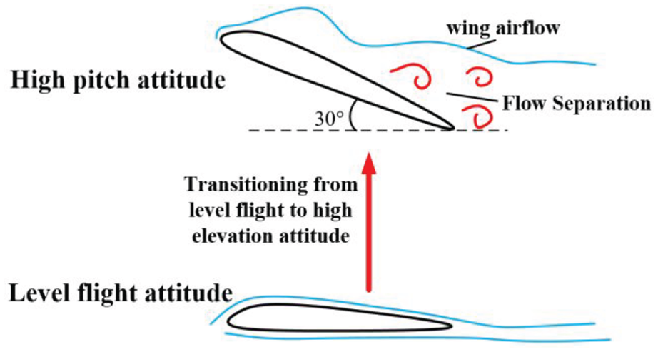
Hysteresis characteristic.
Using OpenVPN, one can approximate the actual pressure distribution on the wing surface, considering propeller slipstream effects. Figure 2 illustrates the wing surface flow field distribution, which is divided into two regions: the propeller slipstream coverage area and the standard noncoverage area. The noncoverage area’s flow field depends solely on airspeed and angle of attack. The propeller slipstream coverage region, driven by propeller rotation, shares identical airflow with the noncoverage area.
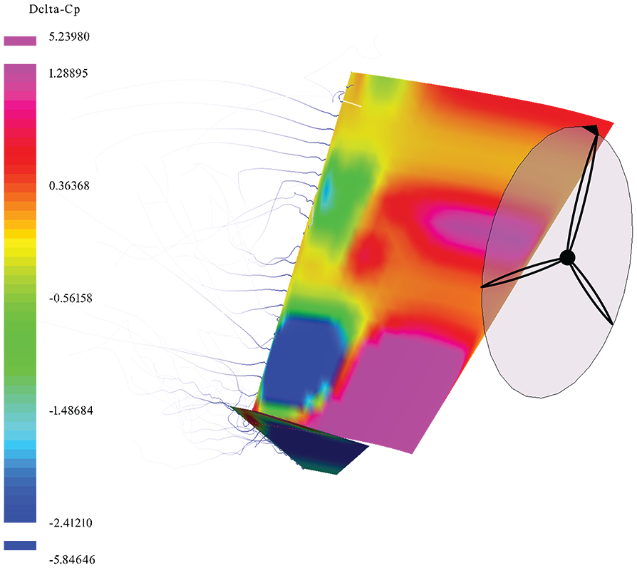
Airflow distribution on wing surface.
The model changes in noncovered areas have significant nonlinear properties due to flow separation hysteresis. In addition to the airflow energy generated by motion, the propeller slipstream is superimposed, resulting in a relatively stable airflow flow state with small changes in actual attack angle and almost no obvious airflow separation phenomenon. Even during static hover, there is enough airflow in this area to power the rudder surface and control the aircraft’s attitude.
The slipstream of the propeller influences the changes in aerodynamic pitch moment and the changes in control surface moment gain, resulting in distinct pitch moments and control surface moment gains in different flow field regions that change dynamically during the aircraft transition. Aerodynamic parameters such as flight speed, angle of attack, and wing flow field condition all have a significant impact on the irregular variations in aerodynamic forces and moments. The model parameters and structural modifications during vertical takeoff and landing vary according to the speed of the transition. This modification presents a substantial difficulty to the design of the rear controller (Ajel et al., 2021).
When describing the angular motion model of a tail-sitter aircraft, taking into account the irregular parameter changes throughout the transition process, equivalent aerodynamic torque, and aerodynamic gain are employed to provide a comprehensive description. Given the numerous literature related to the control of tail-sitter aircraft and the already used tail-sitter unmanned aerial vehicle products, from the perspective of system hardware, this article believes that under the reasonable design of the aircraft’s aerodynamic shape and rudder surface, the rudder surface and differential control method of tail-sitter aircraft can meet the requirements of aerodynamic torque and aerodynamic gain changes on control torque. Thus, the aircraft can be described using a reduced angular motion model (Chen et al., 2022).
Define the aircraft’s body coordinate system for ease of description, as seen in Figure 3.
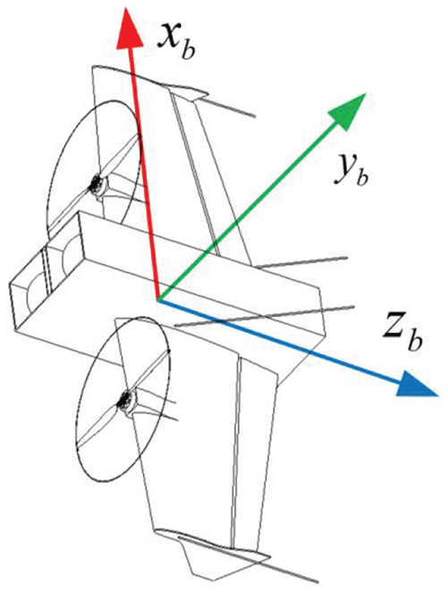
Definition of body coordinate system.
Before establishing the model, we first declare the variables.
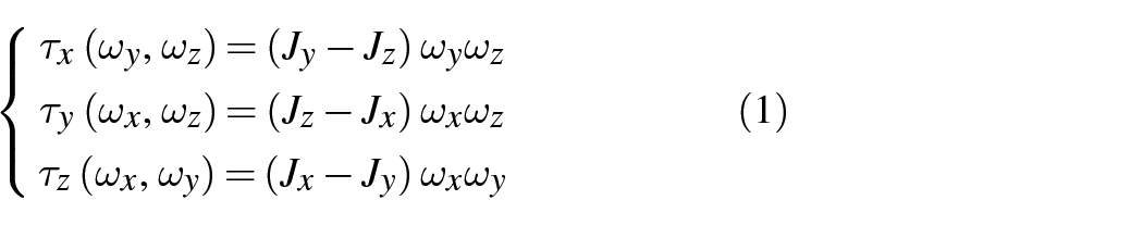
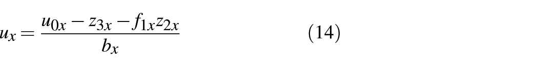
So the torque model of the x-axis of the body can be defined as follows
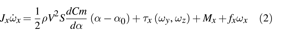
The control amount is transferred to the electric steering gear via the Pulse Width Modulation (PWM) signal until the aerodynamic force changes, and each link responds with a given degree of delay, allowing it to be viewed as a first-order inertial link. Furthermore, in the ADRC framework, this small model error is calculated by the enlarged disturbance observation and then neutralized by the control quantity. The transfer function from the control quantity to the torque can be calculated as
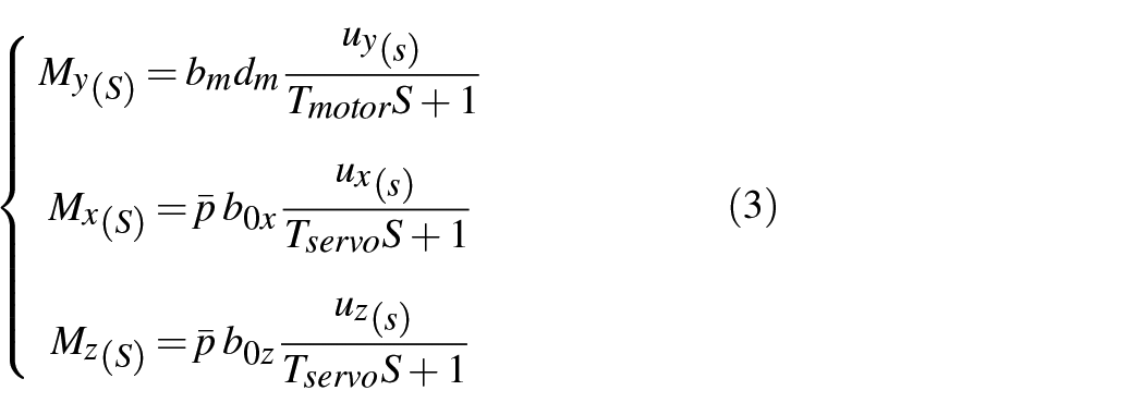
where
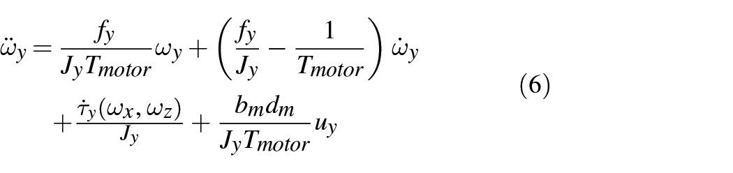
Transforming the transfer function of equation (3) into a parallel vertical differential equation (2), we sorted out the following equation
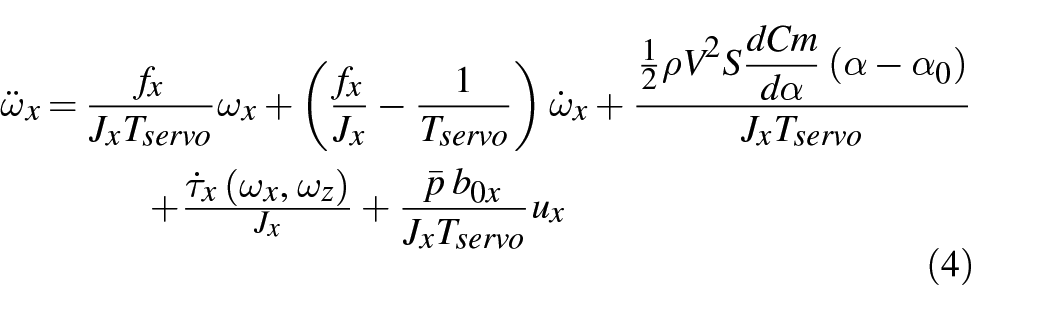
Due to the symmetry of the transverse rolling axis, there is no static aerodynamic pitch moment, and its second-order form is
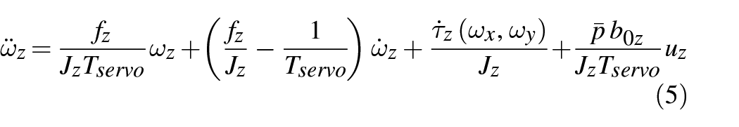
The wing’s projection area in differential direction is the smallest; therefore, the wing’s aerodynamic damping can be neglected. The second-order model for the propeller’s damping torque with decreased amplitude is as follows
Active disturbance rejection controller with dynamic pressure gain compensation
Active disturbance rejection controller
Based on the model form established and improved in the previous text, suitable for second-order auto-disturbance rejection control, a corresponding active disturbance rejection controller is designed. Combined with the dynamic pressure distribution detected in different flow fields, the control gain of the active disturbance rejection controller is adjusted, and the total disturbance observation and compensation ability of the active disturbance rejection controller is utilized to estimate and cancel the aerodynamic torque changes during the transition process in real time.
In Figure 4,
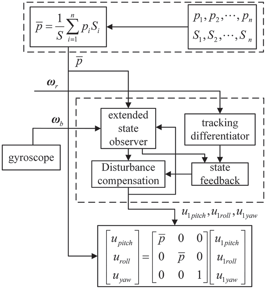
Overall schematic diagram of angular velocity control system.
Figure 5 shows that the ADRC permits parameters to alter within a defined range. Even if some of them fail or the measurements are wrong, as long as they can track the flying state and output measurement parameters that can roughly track the changes, the final transition control effect will be minimally impacted.
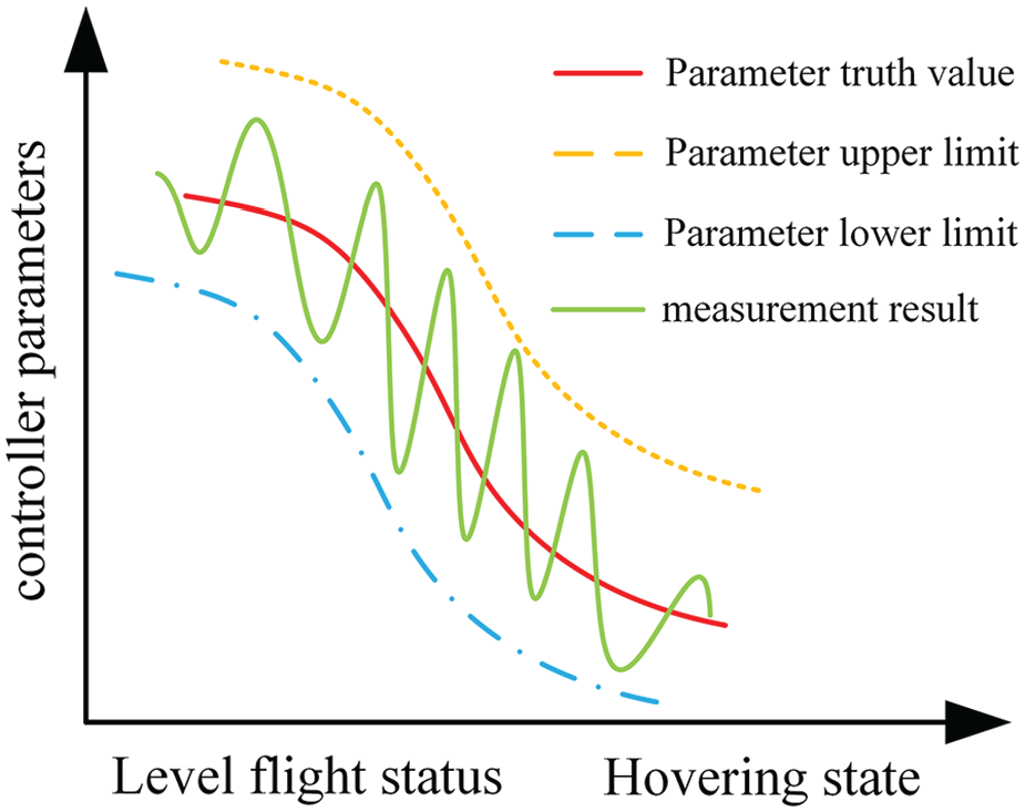
Inaccurate dynamic pressure measurement in a wide parameter range.
Distributed dynamic pressure measurement system
In the specific implementation, considering the experimental cost, when dividing the actual flow field, the flow field distribution is divided into the least two types of distribution areas. The dynamic pressure on the rudder surface in each area is considered to be uniformly distributed, and at least two dynamic pressure probes are used, respectively arranged inside and outside the sliding flow coverage area on the left and right wings (as shown in Figure 6).
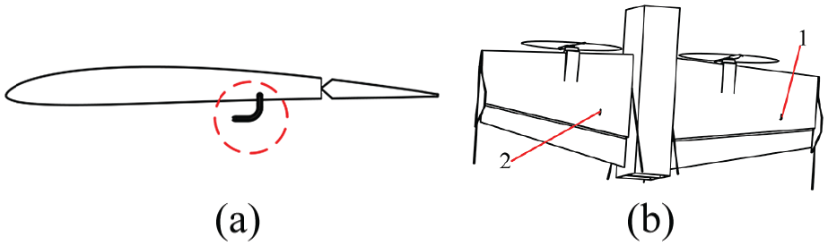
Installation and distribution of dynamic pressure probes. (a) Probe mounting position. (b) Distribution of dynamic pressure probes.
The hardware dynamic pressure estimation measurement is based on the average dynamic pressure; because different sections of the rudder surface rotate simultaneously, the rudder surface gain is calculated using an average equivalent dynamic pressure. General rudder surfaces’ aerodynamic control force can be explained using the following model
where

Based on the distribution of airflow on the rudder surface, the weighted average of the dynamic pressure in each area can be derived as the average dynamic pressure for an equivalent single area
Improved active disturbance rejection control law
Obtain real-time average dynamic pressure based on the distributed dynamic pressure detection system and equation, and calculate the gain of pitch control quantity bx and roll control quantity

where
According to the model, the expanded State observer on the three engine block axes is designed, taking the x-axis as an example
where
The angular velocity controller uses a classic differential tracker as the feedforward link to preprocess the input signal and extract the processed differential signal, to design a second-order state feedback link and obtain better input response dynamics. The specific expression of the differential tracker is as follows
where
The state feedback controllers on three airframe axes are constructed and corrected for total disturbance using the provided input angular velocity and observer information. State feedback employs a function to generate nonlinear feedback for three body axes, resulting in optimal control quantities

where
The uncertainty over attitude, related to the sensor noise, can be characterized using the underlying probability density function (PDF) of unit quaternion on S3.
Afterward, the total disturbance is compensated to obtain the actual control amount
Similarly, the control algorithm design for the y-axis and z-axis is consistent with the x-axis.
Simulation and flight test validation
Simulation
To test the effectiveness of distributed dynamic pressure detection and compensation, numerical simulations of angular speed control are performed within the flight speed range. First, a comparison of PID (proportional−integral−derivative) gain switching and ADRC dynamic pressure compensation is simulated. The situation of dynamic pressure compensation ADRC in constant dynamic pressure but inaccurate measurement and dynamic pressure measurement tracking lag is then simulated to verify the need for dynamic pressure compensation, as well as the active disturbance rejection controller’s anti-interference ability and parameter adaptability.
Figure 7(a) shows the comparison of anti-interference ability between a fixed 17 m/s average airspeed and a carefully tuned PID, with a square wave with an interference torque of 50% duty cycle, a period of 3 seconds, and an amplitude of 1.5 N * m. Figure 7(b) shows the comparison between PID gain switching and ADRC dynamic pressure compensation, simulating the equivalent airspeed and angle of attack changes during vertical transition flight.
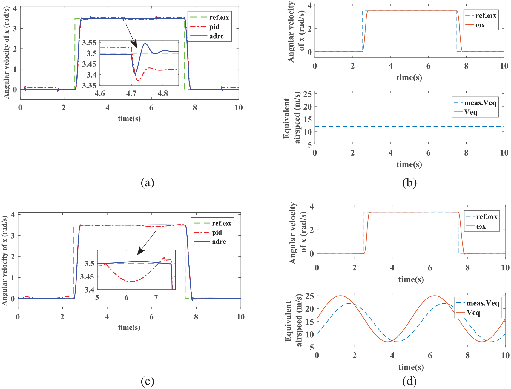
Performance comparison and control effects. (a) Comparison of PID and ADRC’s anti-interference capabilities. (b) Comparison of full process PID gain switching and ADRC dynamic pressure compensation. (c) ADRC control effect under constant airspeed measurement error. (d) ADRC control effect under airspeed measurement lag.
Figure 7(a) shows that ADRC responds very quickly to disturbances, with the angular velocity waveform swiftly matching the reference angular velocity with only a tiny glitch, whereas PID exhibits a considerable static inaccuracy over a lengthy period; In Figure 7(b), the control effect of ADRC dynamic pressure compensation in vertical to horizontal transition flight is significantly better than that of PID gain switching. The constant value measurement error in Figure 7(c) reflects the good parameter adaptability of the active disturbance rejection controller. In Figure 7(d), the lag effect of dynamic pressure measurement on diagonal velocity tracking has hardly weakened, indicating that as long as the distributed dynamic.
The simulation results indicate that the tail-sitter aircraft’s angular velocity control system, based on ADRC dynamic pressure gain adjustment compensation, is adequate to deal with variations in aerodynamic torque and control torque gain of the rudder surface. Simultaneously, the angular velocity control tracking reaction is precise and quick, confirming the scheme’s usefulness.
Hardware and sensors
To verify the effectiveness of the ADRC dynamic pressure gain adjustment compensation angular velocity control scheme proposed in this article, a tail-mounted aircraft was designed and constructed as shown in Figure 8. The aircraft has a wingspan of 1.6 m, a fully loaded takeoff weight of 3.2 kg, and a strong load transportation capacity.
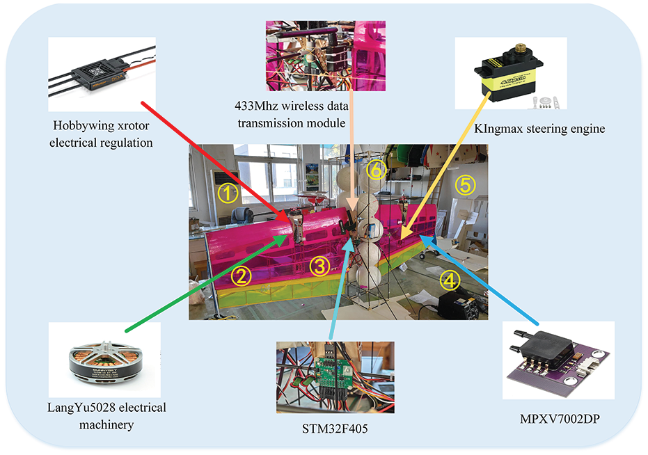
Aircraft physical object and hardware module.
To detect the dynamic pressure of the airflow passing through the rudder surface, the probe should be placed as close as possible to the rudder surface, in front of the rudder surface rotation axis, in the upper and lower directions of the wing. If it is placed on the upper surface of the wing, the probe is easily covered by the low-pressure vortex region during airflow separation, which seriously affects the measurement data. To prevent the impact of wing airflow separation during normal transition, the probe is placed on the lower surface of the wing.
The hardware of the control system mainly consists of a self-designed STM32 flight control board and two simulated airspeed sensors, namely differential pressure sensors. The STM32 flight control board is responsible for running the control algorithm described in this article and receiving and returning data. The differential pressure sensor is responsible for collecting dynamic pressure signals inside and outside the slip flow area and transmitting them to the STM32 flight control board for dynamic pressure gain compensation.
To drive the 18-inch diameter propeller appropriate for vertical takeoff and landing utilized in this aircraft, the Sunnysky 5208 disk motor is selected at 340 kV to obtain a greater speed to match the needs of level flight; Add two 12 g micro actuators and a 40a electronic governor to complete the power system hardware needed for flight testing. Simultaneously, two independent regulated power sources are selected to supply power to the flight control board and the servo, preventing fluctuations in the servo’s output current from impacting the flight control power supply stability.
Flight test plan and flight data analysis
After simple data frame packaging, flight data are connected to a wireless data transmission module with a frequency of 433 MHz through a serial port, and recorded in binary form on a computer. Later, the data are converted into text format through offline decoding. Each frame of data includes observer data, gyroscope data, attitude angle data, and remote control command signals, with a sampling frequency of 50 Hz. Conduct round-trip flight tests on the playground, with an emphasis on the transition from level flight to landing due to the limited distance and short level flying time. Figure 9 depicts the process of an airplane landing at high angles of attack via stall, delivering the predicted smooth and smooth control effect of the flight control system described in this study.
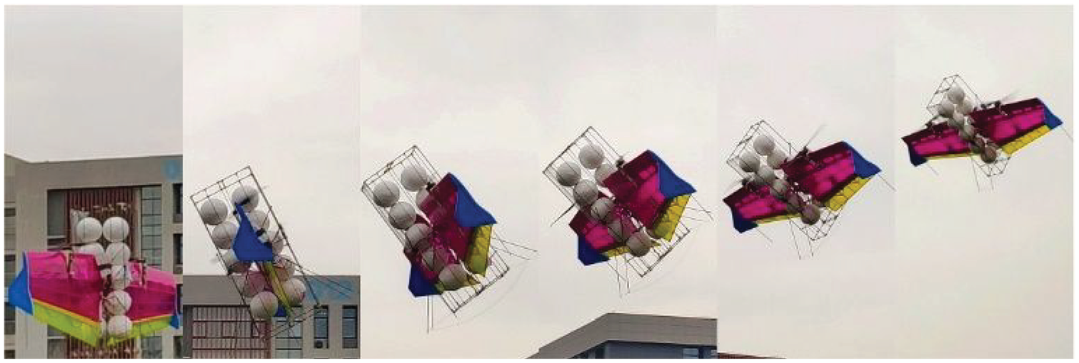
Stable transition landing process of a tail-sitter aircraft at high angles of attack.
To compare the classic PID control method with the dynamic pressure gain compensation improved Active Disturbance Rejection Control (ADRC) method suggested in this research, two flight tests were carried out using both control methods on the flight control system. The experimental findings show that during vertical takeoff and landing, the upgraded ADRC controller can very quickly manage disturbance responses, and the actual angular velocity can soon follow the reference angular velocity. The PID controller, on the other hand, demonstrates a significant tracking deviation, which is essential during flight. The ADRC controller clearly outperforms the standard PID controller in terms of control efficacy during dynamic pressure compensation for vertical takeoff and landing transition flight.
Figure 10(a) shows the comparative flight data of using PID for angular velocity control, and tuning the controller parameters with hovering state as the balance point. It can be seen that as the pitch angle gradually decreases, the equivalent dynamic pressure gradually increases. During the period of 9.5 to 11 seconds, the maximum dynamic pressure reaches 160 Pa, causing a significant deviation in the model parameters. The low-frequency oscillation amplitude of the aircraft’s pitch angle and pitch angular velocity becomes larger and larger, showing a divergence trend. At the same time, the differential control of the aircraft’s z-axis angular velocity with ailerons is also greatly affected, showing a similar divergence trend as pitch control.
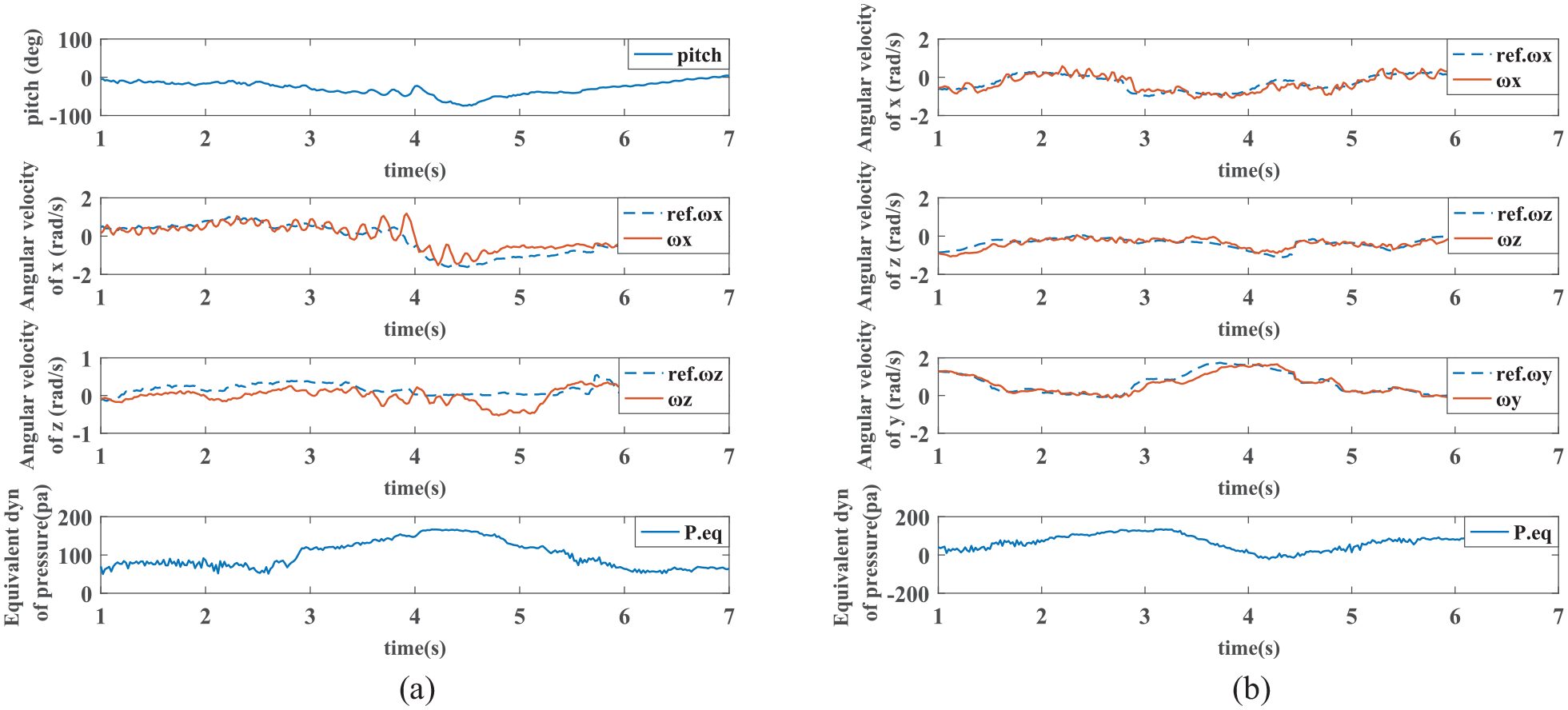
Flight experiment control effect comparison. (a) PID control. (b) Dynamic pressure compensation auto-disturbance rejection control.
As shown in Figure 10(b), using the control method proposed in this article, during the entire flight of the angular velocity stabilization mode, the average dynamic pressure changes between approximately 50 and 150 pa, and the controller gain changes by 300%. The x-axis angular velocity changes roughly within the range of ±1 rad/s, the z-axis angular velocity changes roughly within the range of −1 to 0.5 rad/s, and the y-axis angular velocity changes roughly within the range of 0 to 1.5 rad/s, as the aircraft is conducting unidirectional circular flight. Due to the need for coordinated turning, the angular velocities of the z-axis and y-axis exhibit synchronous changes with polarity. The overall tracking effect of the angular velocity is good, and it is not affected by dynamic pressure changes. The delay between the actual angular velocity and the reference angular velocity is maintained at around 0.2 seconds, especially for the y-axis, which is a motor differential control method with better control force and response speed than the rudder surface. The two body axes are controlled by the rudder surface, due to the introduction of dynamic pressure compensation. The introduction of dynamic pressure compensation slightly affects the Infinite Impulse Response (IIR) filtering effect, possibly due to the high-frequency noise signals generated by the dynamic pressure sensor, causing the angular velocity curve to sometimes exhibit oscillations with an amplitude of 0.5 rad/s, with a frequency consistent with the dynamic pressure noise. Further improvements will be considered.
Conclusion
In response to the issue of model changes during the transition process, this paper proposes a distributed dynamic pressure detection gain adjustment based active disturbance rejection angular velocity control method. The model is simplified according to the characteristics of the ADRC, and the distributed dynamic pressure detection system is used to provide real-time and accurate control quantity gain compensation for the ADRC. At the same time, the total disturbance observation compensation capability of the ADRC is used to track and cancel the aerodynamic pitching torque, dynamic pressure measurement error, and other unmodeled dynamics with small amplitude or slow change during the transition process. The two complement each other and effectively improve the stability and robustness of transition control. The tracking delay of the aircraft’s angular velocity during normal flight is only 0.2 seconds.
Footnotes
Declaration of conflicting interests
The author(s) declared no potential conflicts of interest with respect to the research, authorship, and/or publication of this article.
Funding
The author(s) disclosed receipt of the following financial support for the research, authorship, and/or publication of this article: This work is jointly supported by the National Natural Science Fund (Grants Nos. 62173179), Postgraduate Education Reform Project of Jiangsu Province (JGKT24_B004), and Jiangsu Provincial Key Laboratory of Culture and Tourism for Nondestructive Testing and Safety Traceability of Cultural Relics.
Data availability statement
The data generated in this study are available from the corresponding author (Prof. Zhou,