






Abstract
In this study, adaptive artificial intelligence control algorithms were designed using the particle swarm optimisation (PSO) method for safe take-off and landing of aircraft. The performance of the designed control algorithms, which were applied to the control of the aircraft’s pitch angle, was compared with each other and with studies in the literature. Integrated squared error (ISE) was used as a fitness function in the design of PSO-based proportional–integral–derivative (PSO-PID), PSO-based fuzzy logic controller (PSO-FLC) and PSO-based self-adaptive fuzzy-PID (PSO-SAF-PID) controllers. Performance comparisons between the designed controllers were made based on the transient behaviours such as overshoot, rise time and settling time, and statistical error analyses including mean squared error (MSE), mean absolute error (MAE), ISE and integrated absolute error (IAE). It was observed that the performance of the PID controller, FLC and SAF-PID controllers improved significantly with the application of the PSO method. First, the mathematical model of the system was derived. Second, traditional control methods (PID control algorithm) and artificial intelligence control methods (FLC and SAF-PID type control algorithms) were designed to control the modelled system. Then, to improve the performance of these designed control algorithms, the optimal control parameters of the PID algorithm were determined using the PSO method. At the same time, membership function weight coefficients of the FLC algorithm and SAF-PID type control algorithm were determined using the PSO algorithm. Determining the control parameters and membership function coefficients at optimum values significantly affects the performance of control algorithms. Optimal control parameters and membership coefficients have significantly improved control performance. Furthermore, tests performed on transfer functions with different system parameters have shown that the PSO-SAF-PID controller is robust.
Keywords
Introduction
In recent years, the civil and military applications of unmanned aerial vehicles have expanded rapidly, leading to a technology race between developed and developing countries. Aerial vehicles are used effectively in many areas, such as search and rescue, security surveillance, traffic control and defence. Control methods in these systems are of critical importance, especially in flights conducted with autopilot. Traditional methods are being replaced by artificial intelligence-based approaches. Aircraft control relies on lateral and longitudinal movements. Autopilot systems ensure safe takeoff and landing by managing the pitch angle. Aircraft longitudinal motion has been attempted to be controlled by using various control methods in the literature (Sudha and Deepa, 2016; Ur Rehman et al., 2021). With these studies, the use of artificial intelligence control methods in this field has also gained momentum. First; It is the application of fuzzy logic controller (FLC) method to the aircraft system. In this direction, many researchers have applied the classical PD and fuzzy-PD control algorithms for controlling the pitch angle and the longitudinal motion of the aircraft (Hušek and Narenathreyas, 2016; Johari et al., 2018; Sayar and Ertunç, 2019; Zadeh, 1965). In another study, traditional proportional–integral–derivative (PID), fuzzy logic-based adaptive PID, fuzzy-PID type controllers, T-S fuzzy-based adaptive control method and sliding mode control methods were designed for the pitch control of aircraft system. These studies represent hybrid studies (Chen et al., 2011; Khalid et al., 2019; Singh, 2016; Wahid and Hassan, 2012; Wang et al., 2024; Xu and Wu, 2021).
Another important issue is to determine the optimum values of the controller parameters, which is a factor that significantly affects the performance of the controller. For example, while the performance of a PID controller depends on control gain coefficients, the performance of an FLC depends on values that determine the limits of membership functions. In general, several optimization methods are used to determine these parameters. Various studies have been carried out in the literature to obtain optimum control parameters in aircraft controller design (Abut and Soyguder, 2022; Amador-angulo et al., 2021; Boukadida et al., 2019; Chowdhury and Nair, 2017; García-Gutiérrez et al., 2019; Ghosh Roy and Peyada, 2017; Hu et al., 2020). Angelin Ponrani and Kirthini Godweena (2021) designed an optimal PID controller to control the aircraft’s pitch angle and optimized the PID gains using particle swarm optimisation (PSO) and firefly algorithms. Comparisons showed that the PSO algorithm provided better performance. Another study presents a modelling and control approach for fluid-thrust-based pitch control (FTV) for a delta-winged unmanned aerial vehicle (UAV). Using equations of motion derived from experimental data, PID controllers optimized with genetic algorithm (GA) and PSO were developed. Simulation results show that the PSO-PID controller provides superior performance compared to other methods (Tanveer and Ahmad, 2023). In a study conducted on aircraft pitch angle control, low-order fractional PID controller parameters were determined using the Harris Hawks Optimization algorithm, and the control process was successfully implemented (Idir et al., 2024).
In this study, first, longitudinal dynamical equations were obtained to control the pitch angle of the aircraft system. Then, conventional PID control, FLC and self-adaptive fuzzy (SAF)-PID control algorithms were designed to control this system, respectively. The performance of the designed controllers largely depends on the control parameters. In this respect, later in this study, to increase the performance of the traditional PID control algorithm, a hybrid PSO-PID controller was designed by optimizing the gain coefficients of the PID controller with the PSO algorithm. The reason why the PSO algorithm is preferred in this study is that it is quite suitable for continuous and multivariable optimization problems due to its easy implementation, fast convergence ability (Tanveer and Ahmad, 2023) and less parameter requirement compared to other metaheuristic methods such as genetic algorithm (GA) (Zhang et al., 2025) and differential evolution (DE) algorithms (Wang and Yu, 2024). In the same way, again, the PSO-FLC controller was designed by optimizing the triangle membership functions at the system inputs and outputs with the PSO algorithm. Finally, the model-independent PSO-SAF-PID controller was designed using the PSO algorithm. The purpose of the designed controllers is to effectively control the pitch angle in autopilot flights and prevent the system from being exposed to unwanted vibrations during its longitudinal motion. It has been seen that the control algorithms applied to the aircraft system give successful results. The contribution of this study to the literature is given below.
Six different control structures, namely PID, FLC, FLC-PID, PSO-PID, PSO-FLC and PSO-FLC-PID, were applied to the same aircraft system and their performances were compared. Thus, a multifaceted evaluation was presented.
The PSO-SAF-PID hybrid adaptive controller has been successfully applied to aircraft pitch angle control. This structure not only provides high performance, but also demonstrates its robustness by maintaining stability against system uncertainties and disturbances.
It was observed that PSO can be easily applied to PID, FLC and SAF-PID controllers and achieves rapid convergence.
The rest of the study is organized as follows. Section ‘Mathematical model of the system’ presents the dynamic modelling of the aircraft system, the linearization process and the derivation of the transfer function. Section ‘Controller designs of the aircraft system’ explains the basic principles of PID, FLC, SAF-PID, PSO-PID, PSO-FLC and PSO-SAF-PID controllers in combination with the PSO algorithm. Section ‘Simulation results and discussion’ presents the simulation results, the corresponding graphical data and the evaluations of these results. Finally, section ‘Conclusion’ summarizes the results of the study and outlines possible directions for future research.
Mathematical model of the system
In this section, the dynamic equations of the aircraft system were derived using Newton’s second law. Aircraft exhibit a total of six motions: three linear velocities (u, v, w) and three angular velocities (p, q, r). In the isometric view in Figure 1, the rolling (ϕ) around the x-axis, pitching (θ) around the y-axis and yawing (ψ) around the z-axis motions were observed. These rotational motions are expressed using Euler angles (
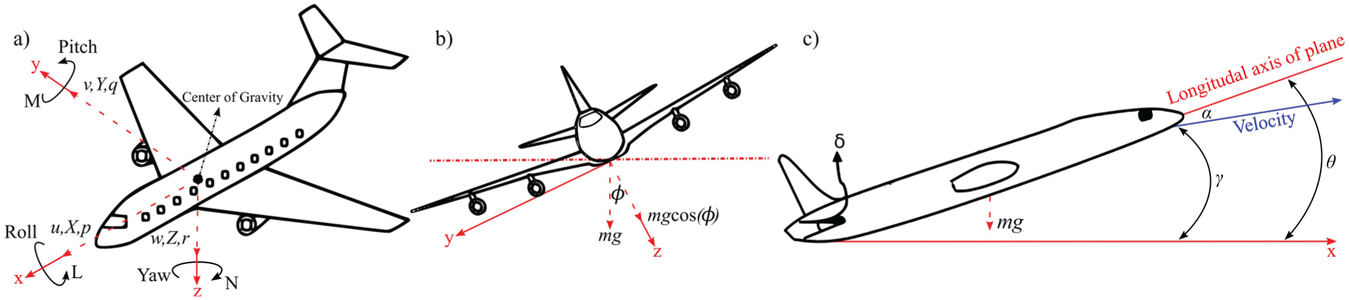
(a) The roll, pitch and yaw motions of an aircraft system. (b) The front view of the aircraft system. (c) The orientation angles of the aircraft system.
In Figure 1(c), the weight of the aircraft (mg) and the relevant angles are shown, namely pitch angle (θ), angle of attack (α), elevator deflection angle (
Using Figure 1, the longitudinal dynamic equations are as shown in equations (1)–(3), respectively (Yu et al., 2018)



Here m represents the mass of the aircraft and g represents the gravitational acceleration. While
Linearization of equations (1)–(3) was performed using the small perturbation approach (Yechout et al., 2003). The variables given in equation (4) are written in their place in equations (1)–(3) by adding small perturbations. While ΔX, ΔY and ΔZ in equation (4) represent the perturbed values of the aerodynamic force components, ΔL, ΔM and ΔN represent the perturbed values of the moments affecting the aircraft. Δu, Δv and Δw show the perturbed values of the linear velocity components, while Δp, Δq and Δr show the perturbed values of the angular velocities. While

As a result of the linearization of equations (1)–(3), it is obtained as in equations (5)–(7), respectively (Wahid et al., 2010). Here, equations (5) and (6) show the force equations acting on the aircraft in the x and z directions, respectively, while equation (7) is the equation of the moment about the y axis of rotation

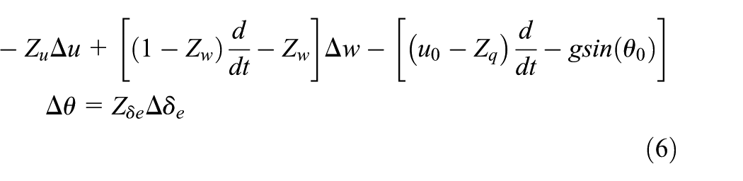

As a result of using the aircraft parameters in equations (5)–(7) and in Table S1 (Johari et al., 2018), the transfer function of the system is obtained as in equation (8). Here, the transfer function expresses the relationship between the pitch angular velocity

The relationship between pitch angle (θ) and pitch angular velocity (q) is as in equation (9). After applying the Laplace transform to the expression above, equation (10) is obtained. After substituting equation (8) in equation (10), as shown in equation (11), the transfer function of the aircraft system whose output is pitch angle



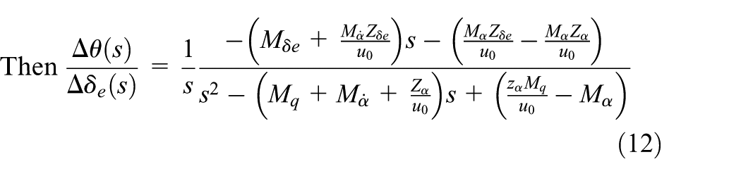

In this section, the dynamic behaviour of the aircraft system was modelled based on Newton’s second law, longitudinal dynamic equations were derived, linearized and analysed by obtaining the transfer function.
Controller designs of the aircraft system
Particle swarm optimization
The PSO has fewer parameters so it is easier to programme. Each individual in the swarm is called a particle. Particles can be defined as candidate solutions to the problem. The positions and velocities of the particles that make up the swarm are initially randomly generated. Individuals in the swarm tend to move towards the best position while determining their new position. Therefore, each individual, while updating its position, determines his new position with the tendency to approach the best position of the herd (gbest) and the behaviour of keeping his best position (pbest). Particle velocities and positions are iteratively refreshed using equations (14)–(16). The flow chart of the PSO optimization is given in Figure S1



Parameters defined as the coefficient of inertia (w), acceleration constants (c
1
and c
2
), maximum iteration (
The integrated squared error (ISE) fitness function (equation (17)) has been effective in quickly eliminating major errors, and its arrangement according to the aircraft system is as in equation (19). Here,




This section explains the basic principles and application steps of the PSO algorithm used in the solution process.
Design of aircraft control algorithms
To control the aircraft system, PID, FLC, SAF-PID controllers were applied, respectively. Then, to increase the performance of the existing controllers, optimization process was applied to each of them and optimized PID, optimized FLC and optimized SAF-PID were obtained, respectively.
Design and modelling of the PID controller algorithm
The mathematical model of the PID control method is given in equation (21). Here,

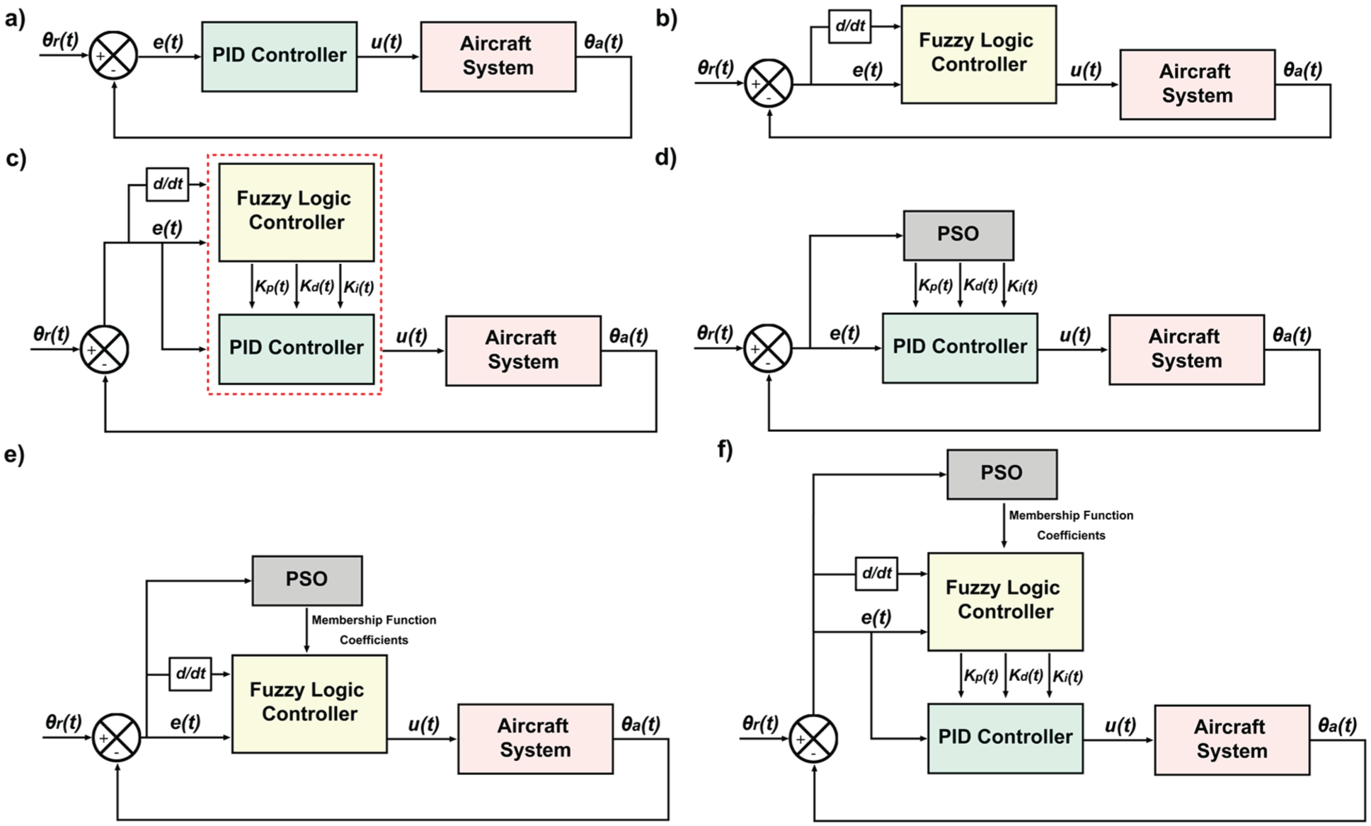
Block diagrams of (a) PID, (b) FLC, (c) SAF-PID, (d) PSO-PID, (e) PSO-FLC and (f) PSO-SAF-PID controllers for the aircraft system.
Design and modelling of the FLC algorithm
The FLC designed in this section consists of the processes of fuzzification, inference, rule base and defuzzification. While the input of the controller is the error
The interval values of the membership functions were determined as [−1.6, 1.6] for
Equations (22) and (23) express the triangular membership function model for fuzzification process. The membership degrees


Equation (24) produces membership degree according to the Mamdani inference method

Equation (25) uses the centroid model for defuzzification to obtain output

Design and modelling of the SAF-PID controller algorithm
The performance of a PID controller depends on the appropriate determination of the
The FLC controller consists of two inputs, three outputs and five membership functions each. While the inputs of the FLC are the error



Equations (29)–(31) show the centroid model for defuzzification. Finally, SAF-PID controller is obtained as shown in equation (32)




Following the classical control approach presented in this section, advanced controllers based on PSO were designed to improve system performance.
Design of aircraft optimal control algorithms using the PSO
Design of the PSO-PID controller method
Determining the control parameters of a system to be supervised can be difficult due to the nature of the system. To increase the performance of the non-optimized controllers designed in the previous section, the optimal


Equations (35) and (36) are used to update the velocity and position of each particle. The w in equation (35) is calculated using equation (16). Finally, when the optimal gain parameters obtained from equation (37) are substituted into equation (38), the PSO-PID controller is obtained




Design of the PSO-FLC controller method
The performance of the FLC controller depends on the accurate determination of membership functions. In this study, membership functions were optimized using the PSO algorithm, thereby designing an optimal FLC.
In Figure 2(e), the block diagram of the PSO-FLC controller designed for the aircraft system is given. While the inputs of the optimal FLC controller consist of


Equations (35) and (36) update the particle’s velocity and position; w in equation (35) is calculated using equation (16). Finally, when the optimal membership boundary values obtained from equation (41) are substituted into equations (42) and (43) optimal membership triangular functions are obtained



When equations (42) and (43) are substituted into equations (24) and then (25), the PSO-FLC controller is obtained.
Design of the PSO-SAF-PID controller method
In this section, the membership functions of the SAF-PID controller are optimized with PSO and an PSO-SAF-PID controller is designed to enhance the controller’s performance. Obviously, this controller design is a multi-hybrid design. As seen in Figure 3, while the membership functions of the FLC controller were determined by PSO, the control gain coefficients of the PID controller (
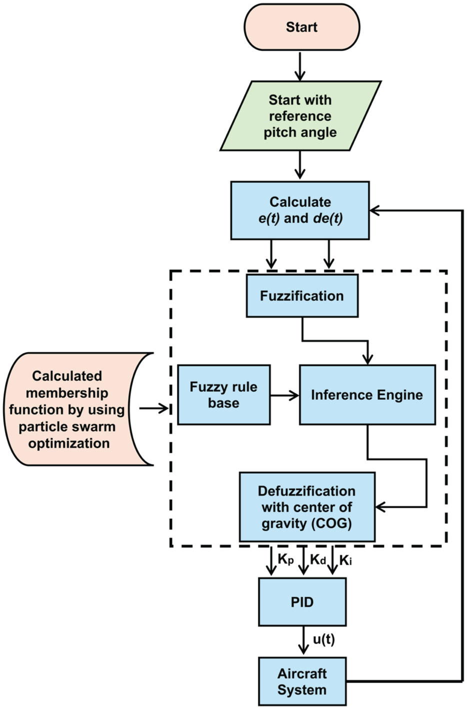
The flowchart of the optimal SAF-PID control algorithm.
The rule table consists of 75 rules in total, designed for the control of the aircraft system. The linguistic expressions used here are NL, NS, Z, PS and PL, respectively. In Figure 2(f), the block diagram of the PSO-SAF-PID controller designed for the aircraft system is given.
In the PSO-SAF-PID controller particle solution vector and fitness function are defined in the same way as in equations (39) and (40). The velocities and positions of the particles are updated using equations (35) and (36). The optimal membership boundary values obtained from equation (43) are substituted into equations (42) and (43) to obtain the optimal triangular membership functions. Equations (26)–(28) produce membership functions according to the Mamdani inference method using the results obtained from the fuzzification process. Equations (29) and (31) show the centroid model for defuzzification. Finally, PSO-SAF-PID controller is obtained.
The flow diagram of the PSO-SAF-PID controller is given in Figure 3. The interval values of the membership functions of the controller were obtained as [−5.388, 3.75] for e(t), [−8, 11.89] for
In this section, PSO-based PID, FLC and SAF-PID controllers were designed, and comparisons between controller performances were presented in the following section.
Simulation results and discussion
In this study, system performance was improved by optimizing traditional and artificial intelligence-based control methods using PSO. The initial pitch angle of the aircraft system was taken as 0°. The reference value for each control algorithm was taken as 1.57 radians, and it was assumed that the aircraft pitch angle would not exceed ±1.57 radians. In this study, each controller was compared with its optimal states and also compared with each other. Most importantly, the performances of our designed control algorithms were compared with the related studies in the literature and the state-of-the-art level of the study was tried to be shown. The parameters of the PSO algorithm used in the optimization of the controllers were taken as 2 for the
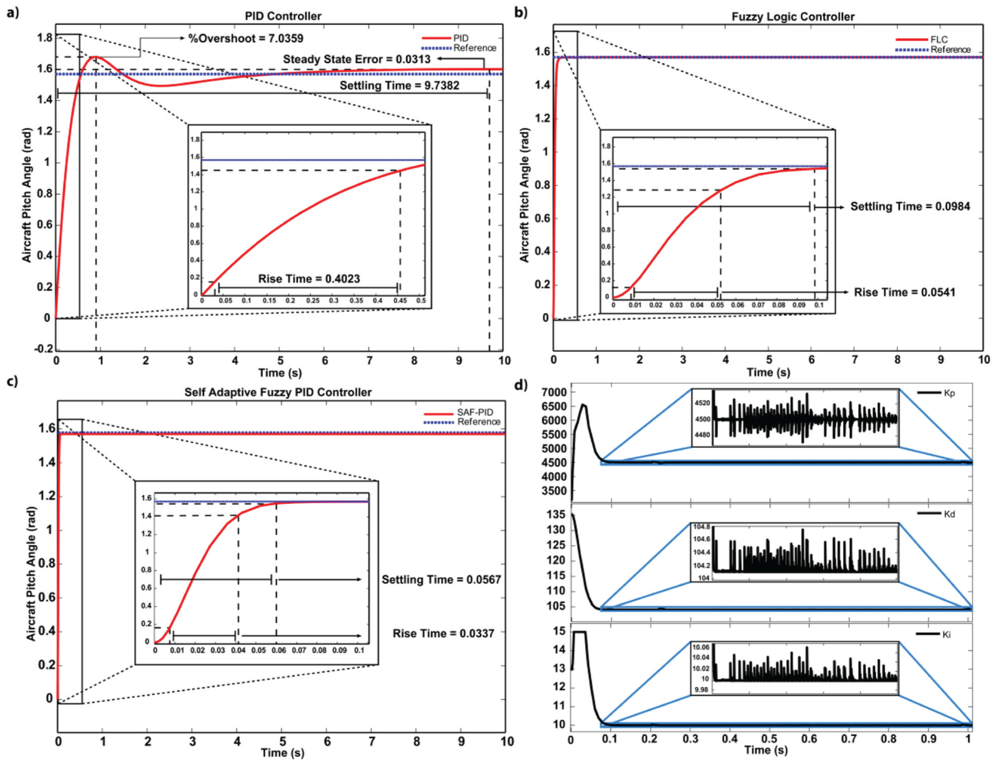
The responses of aircraft system under (a) PID, (b) FLC and (c) SAF-PID controllers, and (d) the obtained gain parameters using the SAF-PID algorithm.
As a result of the FLC demonstrated in Figure 4(b), the settling time of the aircraft system was determined as 0.0984 seconds. The transient behaviour of the system was very short and the reference pitch angle was reached quickly. In addition, it was observed that the steady-state error of the control was 5 × 10⁻⁵.
As a result of the SAF-PID in Figure 4(c), the settling time of the aircraft system was determined as 0.0567 seconds. Similarly, the transient behaviour of the system was very short and the reference pitch angle of 1.57 radians was reached quickly. In addition, it was observed that the steady-state error of the control was 2 × 10⁻⁵. Figure 4(d) shows the obtained gain parameters according to SAF-PID. The optimal values of the control parameters were determined within approximately 0.1 s. These values were obtained as
The result of the PSO-PID controller applied to the graphic aircraft system seen in Figure 5(a) was obtained. It took 0.2042 seconds for the aircraft system to reach a reference input value of 1.57 radians, with a maximum overshoot of 14.6260%. As a result of the hybrid implementation of the PID controller with the PSO algorithm, the PSO-PID controller has achieved a faster transient behaviour compared to the traditional PID control and has become stable. In addition, it was observed that the steady-state error of the control was 2.4 × 10⁻⁴. In Figure 5(d), the convergence graph of the fitness function value, which shows the change in controller performance, is given in each iteration. After approximately the fourth iteration, the amount of convergence started to reach a stable value. In each iteration, a solution was sought using 30 particles. The ISE value started around 0.084 and decreased to 0.06916. The result of applying the PSO algorithm was obtained as
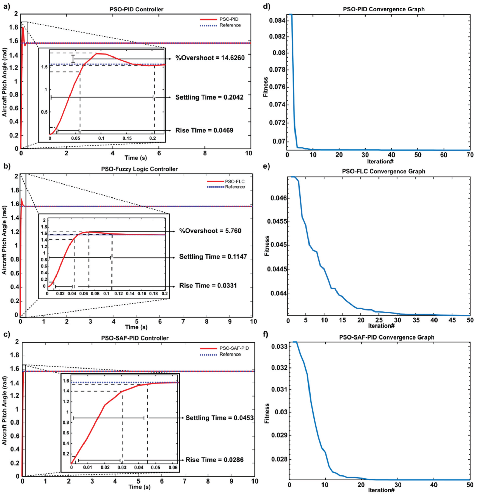
Responses of (a) PSO-PID, (b) PSO-FLC, (c) PSO-SAF-PID controllers and (d), (e), (f) the convergence curves the PSO-based optimization processes.
The graphic shown in Figure 5(b) is obtained as a result of the PSO-FLC controller applied to the aircraft system. It took 0.1147 seconds for the aircraft system to reach the 1.57 radian reference input value, with a maximum overshoot of 5.76%. In addition, it was observed that the steady-state error of the control was 2.9 × 10⁻⁴. As a result of the hybrid application of the FLC controller with the PSO algorithm, the performance of the PSO-FLC controller compared to the FLC control has improved. In Figure 5(e), the convergence graph of the fitness function value, which shows the change in PSO-FLC controller performance, is given in each iteration. After approximately the 35th iteration, the convergence value started to reach a stable value. The ISE decreased to 0.04416. As a result of the application of the PSO algorithm, the membership functions were obtained as [−1.3, 1.513] for e(t), [−55, 52.461] for
It is obtained as a result of the PSO-SAF-PID controller applied to the graphic aircraft system in Figure 5(c). It took 0.0453 seconds for the aircraft system to reach the 1.57 radian reference input value. In addition, it was observed that the steady-state error of the control was 1 × 10⁻⁵. As a result of the hybrid application of the SAF-FLC controller with the PSO algorithm, it was observed that the PSO-SAF-FLC controller performed better than the SAF-FLC control. In Figure 5(f), the convergence graph showing the variation of the fitness value of the PSO-SAF-PID controller with the number of iterations is given. After approximately the 20th iteration, the convergence value stabilized. ISE has decreased to 0.02711. As a result of the application of the PSO algorithm, the membership functions were obtained. Here, the NL membership function in
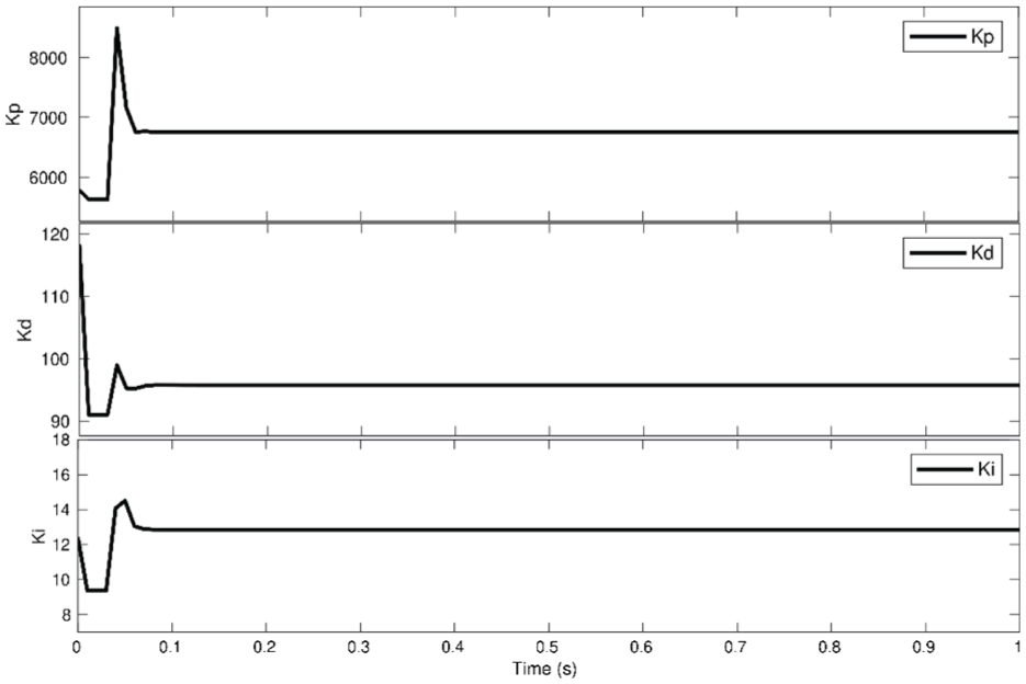
As seen in Figure 6, the gain coefficient values obtained as a result of PSO-SAF-PID were
Six different control methods have been applied to control the pitch angle of the aircraft during takeoff and landing. These methods are, respectively, the conventional PID controller, FLC, SAF-PID controller, optimal PID controller, optimal FLC and optimal SAF-PID. Comparison of these methods with each other is given in Figure 7(a). As seen in Table S4, the PSO-SAF-PID controller has the best performance results in general, according to percent overshoot, rise time, settling time and steady-state error performance indexes. When a comparison is made between FLC and PSO-FLC, while PSO-FLC gives better results than rise time and steady-state error, FLC performs better results compared to percent overshoot and settling time. According to the comparison between PID and PSO-PID controllers, PSO-PID gave better results than rise time, settling time and steady-state error performance indexes. As a result of using ISE error analysis as a fitness function, large errors are quickly eliminated as the squares of the errors are taken, and therefore, percent overshoot values in PSO-PID and PSO-FLC controllers are larger than PID and FLC controllers. Most importantly, it has been observed that the percent overshoot value is eliminated as a result of the application of the PSO-SAF-PID controller, which is the control method.
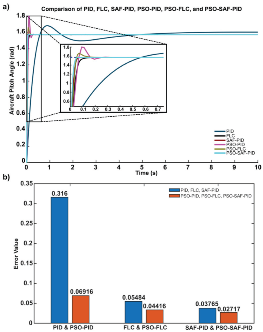
Performance comparison of (a) implemented control methods in terms of (b) ISE data in Table S4.
In addition, the performance criteria of the controllers designed for the control of the aircraft system were evaluated according to the statistical error analysis methods MAE, MSE, IAE and ISE methods and Table S4 has also been given. Statistical error analysis methods used in equations (44)–(47) are given. Here




As a result of applying the PSO algorithm to PID, FLC and SAF-PID controllers, the performance improvements of all three controllers are seen in Table S4 and Figure 7(a). Figure 7(b) is drawn using the ISE data in Table S4. After applying the PSO algorithm, the improvements and change in the performance of the controllers is shown with bar graphs (Figure 7(b)). It is determined as 10 seconds for each controller of the simulations performed in MATLAB/Simulink. According to the simulations, first; for the PID controller, the best result was obtained from the ISE method with 0.316 radians, while the worst result was obtained from the MSE method with 0.8461 radians. The best result for the FLC controller was obtained from the MAE method with 0.0535 radians, while the worst result was obtained from the MSE method with 0.0758 radians. For the SAF-PID controller, the best result was obtained from the MAE method with 0.0243 radians, while the worst result was obtained from the IAE method with 0.03736 radians. Then, as a result of applying the PSO algorithm, the best result for the PSO-PID controller was obtained from the ISE method with 0.06916 radians, while the worst result was obtained from the MSE method with 0.1349 radians. As a result of applying the PSO algorithm to the PID controller, a performance increase of 78.11% was observed compared to the ISE method. For the PSO-FLC controller, the best result was obtained from the ISE method with 0.04416 radians, while the worst result was obtained from the MSE method with 0.0919 radians.
As a result of applying the PSO algorithm to the FLC controller, it has been observed that there is a 19.47% improvement in its performance compared to the ISE method. Finally; For the PSO-SAF-PID controller, the best result was obtained from the MAE method with 0.0033 radians, while the worst result was obtained from the ISE method with 0.02611 radians. As a result of applying the PSO algorithm to the SAF-PID controller, it has been observed that there is a 30.65% improvement in its performance compared to the ISE method. Figure 7(b) is plotted using the ISE data in Table S4. After applying the PSO algorithm, the change in the performance of the controllers is shown with bar graphs (see Figure 7(b)).
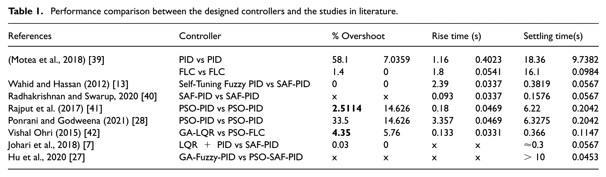
The comparison between the studies in literature and the designed controllers is given in Table 1. While the red-coloured data in Table 1 shows the performance indexes of the controllers designed in this study, the other data includes the data of the studies in the literature.
Performance comparison between the designed controllers and the studies in literature.
The controller’s ability to perform stably under various dynamic conditions requires the robustness of the system. Figure 8 shows the step response graphs of four different transfer functions. Disturbance effects acted on the systems at 1st, 4th and 7th seconds. The gains of the PSO-SAF-PID controller are adjusted adaptively against disturbance effects.
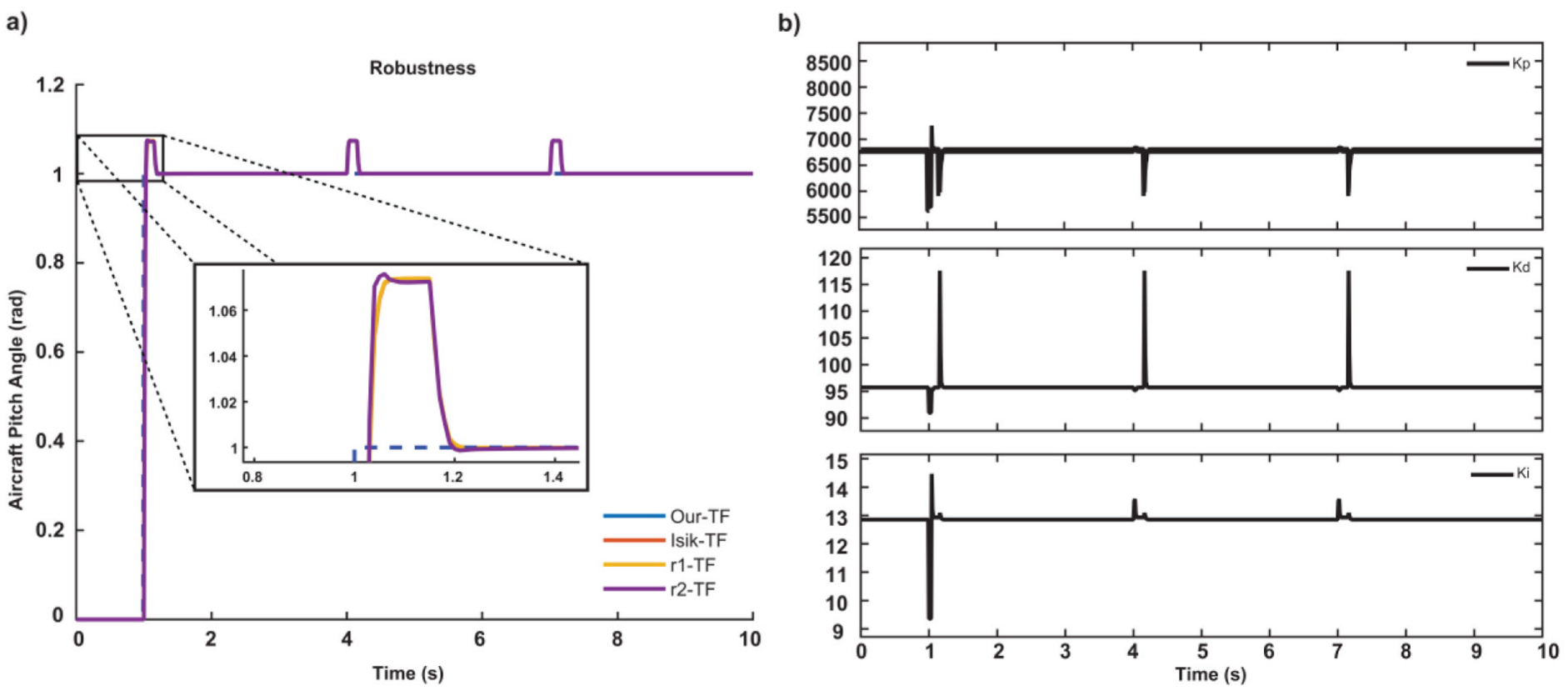
The PSO-SAF-PID tests demonstrate (a) the robustness of the control structure against varying system dynamics and (b) the change in adaptive controller gains against disturbance effects.
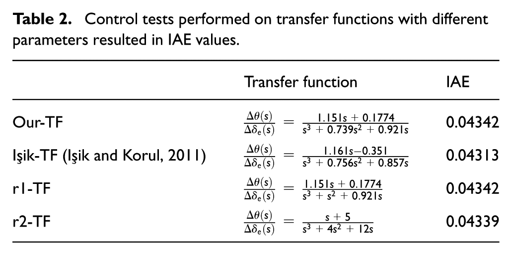
As shown in Table 2, IAE values are given because of control tests performed on transfer functions with different parameters. The similarity between the graphs and the IAE values reveal that the model shows robust performance against parameter uncertainties.
Control tests performed on transfer functions with different parameters resulted in IAE values.
Conclusion
In this study, pitch control was performed in autopilot mode by creating a dynamic model of the aircraft system. For this purpose, PID, FLC, SAF-PID, PSO-PID, PSO-FLC and PSO-SAF-PID controllers were designed in that order. The PID gain coefficients were obtained adaptively in SAF-PID controller. The PSO algorithm was used to increase the performance of PID, FLC and SAF-PID controllers. The PID gains, the parameters forming the triangle membership functions of the FLC and SAF-PID controllers were optimized with the PSO algorithm. According to the convergence graphs, improvements have been seen in the performance of the controller applied to the aircraft system (see Figure 5). The control parameters (K p , K d and K i ) obtained in the SAF-PID controller made small oscillations after about 0.1 seconds, but the control parameters obtained with the PSO-SAF-PID controller reached a stable value after approximately 0.1 seconds. As a result of applying the PSO algorithm, the performances of the controllers in Table S4 were compared in Figure 7 according to ISE method. The results increased by 78.11% for PID, 19.47% for FLC and 30.65% for SAF-PID, respectively. The robustness of the system under different parameters was verified by the error values in Table 2. As a result, it has been demonstrated that the PSO-SAF-PID controller can adapt to different system dynamics.
In future studies, the aim is to design an experimental model of the existing system and test the real-time application and performance of the controller.
Supplemental Material
sj-docx-1-tim-10.1177_01423312251376232 – Supplemental material for Performance comparisons of self-adaptive artificial intelligence control algorithms designed using particle swarm optimization in aircrafttakeoff and landing
Supplemental material, sj-docx-1-tim-10.1177_01423312251376232 for Performance comparisons of self-adaptive artificial intelligence control algorithms designed using particle swarm optimization in aircrafttakeoff and landing by Ahmet Sadık Duru and Servet Soyguder in Transactions of the Institute of Measurement and Control
Footnotes
Author contributions
Ahmet Sadık Duru: Formal analysis, Investigation, Methodology, Conceptualization, Data curation, Writing – review & editing. Servet Soygüder: Methodology, Investigation, Conceptualization, Writing – review & editing, Project administration, Funding acquisition.
Declaration of conflicting interests
The authors declared no potential conflicts of interest with respect to the research, authorship, and/or publication of this article.
Funding
The authors disclosed receipt of the following financial support for the research, authorship, and/or publication of this article: This study was supported by the Scientific Research Projects Department of Ankara Yıldırım Beyazıt University. Project Number: FDK-2023-2565.

Data availability statement
Data sharing not applicable to this article as no datasets were generated or analyzed during the current study.
Supplemental material
Supplemental material for this article is available online.
References
Supplementary Material
Please find the following supplemental material available below.
For Open Access articles published under a Creative Commons License, all supplemental material carries the same license as the article it is associated with.
For non-Open Access articles published, all supplemental material carries a non-exclusive license, and permission requests for re-use of supplemental material or any part of supplemental material shall be sent directly to the copyright owner as specified in the copyright notice associated with the article.
