
Abstract
This paper presents a grid-connected photovoltaic system in which a two-level voltage source inverter operates as a shunt active power filter. A hybrid control strategy combining an Adaptive Linear Neuron (Adaline) with Direct Power Control (DPC) is proposed. In this control, Adaline extracts reference powers, while DPC generates the optimal switching signals through a switching table, without the need for a separate Pulse Width Modulation (PWM) or hysteresis modulation stage. The system performance is evaluated with MATLAB/Simulink simulations under various conditions, including linear and nonlinear loads as well as constant and variable irradiance. Simulation results confirm that the photovoltaic (PV) system effectively delivers active power to the grid while compensating for harmonic and reactive currents. The total harmonic distortion with the Adaline-DPC remains below 5% of the IEEE-519 standard limit. Although the Adaline-DPC has a higher computational burden, it outperforms the conventional hybrid DPC methods such as conventional DPC (CDPC), HSF instantaneous active and reactive power control with DPC (HSFDPC), SRF control with DPC (SRFDPC), and HSFSRF control with DPC (HSFSRF-DPC) by providing lower THD under both ideal and nonideal source and load conditions.
Keywords
Introduction
The global use of renewable energy sources (RESs) is increasing rapidly, enabling technological and economic optimization while simultaneously addressing growing energy demand and reducing pollutant emissions (Jung et al., 2014; Zellagui et al., 2024). Among these sources, solar photovoltaic (PV) energy is one of the most important RESs. The PV systems have diverse advantages, such as zero emissions, low cost, fewer maintenance requirements, simplicity of construction, unlimited availability, and widespread distribution (Daia Eddine et al., 2023; Molina and Espejo, 2014). In grid-connected PV systems, the voltage source inverter (VSI) can also be operated as a shunt active power filter (SAPF). In this configuration, the PV system delivers its maximum power to the grid while reducing current distortion.
Current distortion mainly arises from the widespread use of nonlinear loads, which absorb harmonic currents and exchange reactive energy. Such distortion leads to many power quality issues, including increased current and voltage harmonics, interference with sensitive equipment, and reduced power factor, all of which can negatively impact the efficiency and stability of the electrical network, as discussed by Bekakra et al. (2021), Kockanat (2020), and Salem et al. (2020). This problem clearly deserves serious consideration, as emphasized by Djazia et al. (2015), making it necessary to respect the IEEE 519-2014 standard (Institute of Electrical and Electronics Engineers, 2014), which recommends that the total harmonic distortion (THD) of current should not exceed 5%.
Many solutions exist in the literature to reduce current distortion caused by nonlinear loads, as explained by Djazia and Sarra (2024), Baazouzi et al. (2022), and Sai Thrinath et al. (2022). Passive filters, however, have various disadvantages, such as resonance issues, fixed compensation, and large size, according to Bachar et al. (2019). To overcome these limitations, the SAPF offered a good solution since it came into view around 1970 (Bekakra et al., 2021; Chennai and Benchouia, 2011).
The performance of the SAPF depends on its control method, which typically involves the identification of the reference signal, the generation of the switching signals, and the control of the DC link voltage. Among the most used reference signal extraction techniques are the instantaneous active and reactive power theory (p–q) and synchronous reference frame (SRF) (Akagi, 1997; Ye et al., 2018).
Adaline (Adaptive Linear Neuron) is a modern neural network control method. It offers a simple and efficient approach for reference signal estimation (Yazdani et al., 2009). Thanks to its online adaptation and learning capabilities, Adaline can estimate reference signals in real time by continuously updating its weights. The design of the Adaline is simple compared to many other neural network controls, as it consists of a single layer of linear neurons and uses only basic linear algebra operations with implementation using least-mean squares (LMS) training rules. On the contrary, conventional p–q and SRF theory require multiple transformations and the use of Low-Pass Filters (LPFs) or High-Selectivity Filters (HSFs). However, the LPF design also faces many challenges: too fast dynamic response leads to poor selectivity, while a good selectivity introduces significant delay (Bany Fawaz et al., 2024). In addition, the algorithm may introduce harmonics in the grid current, namely, hidden currents, which are not present in the load currents (Czarnecki, 2006; Valedsaravi et al., 2023).
Moreover, these conventional methods rely on fixed transformations that assume ideal sinusoidal and balanced voltages. As a result, their performance degrades under nonideal source and load conditions (Baros et al., 2022; Hoon et al., 2017).
Direct Power Control (DPC) is another control strategy that has gained attention due to its fast dynamic response, simple implementation, and acceptable current ripple (Ouchen et al., 2021). The DPC permits the direct generation of the VSI switching signals without requiring reference-signal extraction, internal controllers, or system modulation.
Recent studies have investigated the application of Adaline in SAPF. Tamer et al. (2021) applied the conventional Adaline control strategy, while PI parameters were optimized using PSO. Ryad et al. (2024) implemented the Adaline for a five-level SAPF. Similarly, Hoon et al. (2019) proposed an Adaline approach for controlling a three-phase four-wire active power filter. Jamlaay (2024) explored the use of Adaline for voltage harmonic mitigation in a three-phase series active power filter. Asadi et al. (2022) employed Adaline to enhance harmonics mitigation and synchronization. Zainuri et al. (2016) integrated PV systems with SAPF and employed Adaline for improved harmonics extraction under dynamic PV and load conditions. To address frequency deviation issues, an improved Adaline with frequency detection methods was proposed by Chen et al. (2018). Simplified Adaline approaches for single-phase SAPF were suggested by Zainuri et al. (2018). Comparative studies by Vardar and Akpinar (2011) showed that Adaline methods implemented on digital signal processors provide competitive performance against p–q methods under various loading conditions.
Parallel to this, several works have focused on improving DPC in SAPF applications. Ouchen et al. (2021) combined DPC with space-vector modulation to maintain a fixed switching frequency and reduce power ripple. Bekakra et al. (2021) introduced a modified predictive DPC optimized with metaheuristic algorithms. Boukezata et al. (2016) proposed switching table optimization to reduce power losses in the inverter of PV-grid-connected SAPF. Mujammal et al. (2024) introduced a grid-voltage-modulated neural network control strategy for DPC in PV systems. Mesbahi et al. (2014) suggested a hybrid control combining conventional DPC (CDPC) with modified p–q theory using HSFs for improved performance under nonideal grid conditions. Daia Eddine et al. (2023) integrated a backstepping-based gray wolf optimization with DPC in PV systems, improving active power injection but introducing tuning challenges.
A review of these studies indicates that most existing works either focus on using a standalone Adaline for signal estimation or on improving CDPC. However, no attempt has been made to integrate both approaches in order to combine the harmonic decomposition capability of Adaline with the fast dynamic response of DPC. To address this gap, this paper proposes a novel control strategy that integrates Adaline with DPC, referred to as ADPC. In this control strategy, Adaline is employed to extract the reference powers without requiring Park/Concordia transformations or LPFs, while DPC generates the optimal switching signals of the VSI. In addition, ADPC is applied to a grid-connected PV system to mitigate harmonic currents, compensate reactive power, and ensure the maximum power delivery to the grid using the incremental conductance method. Finally, the performance of ADPC is evaluated against CDPC, HSFDPC, SRF DPC, and Self-Tuning Filter-SRF DPC (STFSRF-DPC) under ideal and nonideal conditions to test its effectiveness and robustness.
This paper contains five sections. Section “System structure” introduces the system structure. Section “Proposed Adaline-based DPC” presents the ADPC control strategy. Section “Simulation results” provides and discusses the results of the simulations. Finally, section “Conclusion” concludes this paper.
System structure
Figure 1 illustrates the structure of the grid-connected PV system. It mainly consists of an electrical source with its impedance (
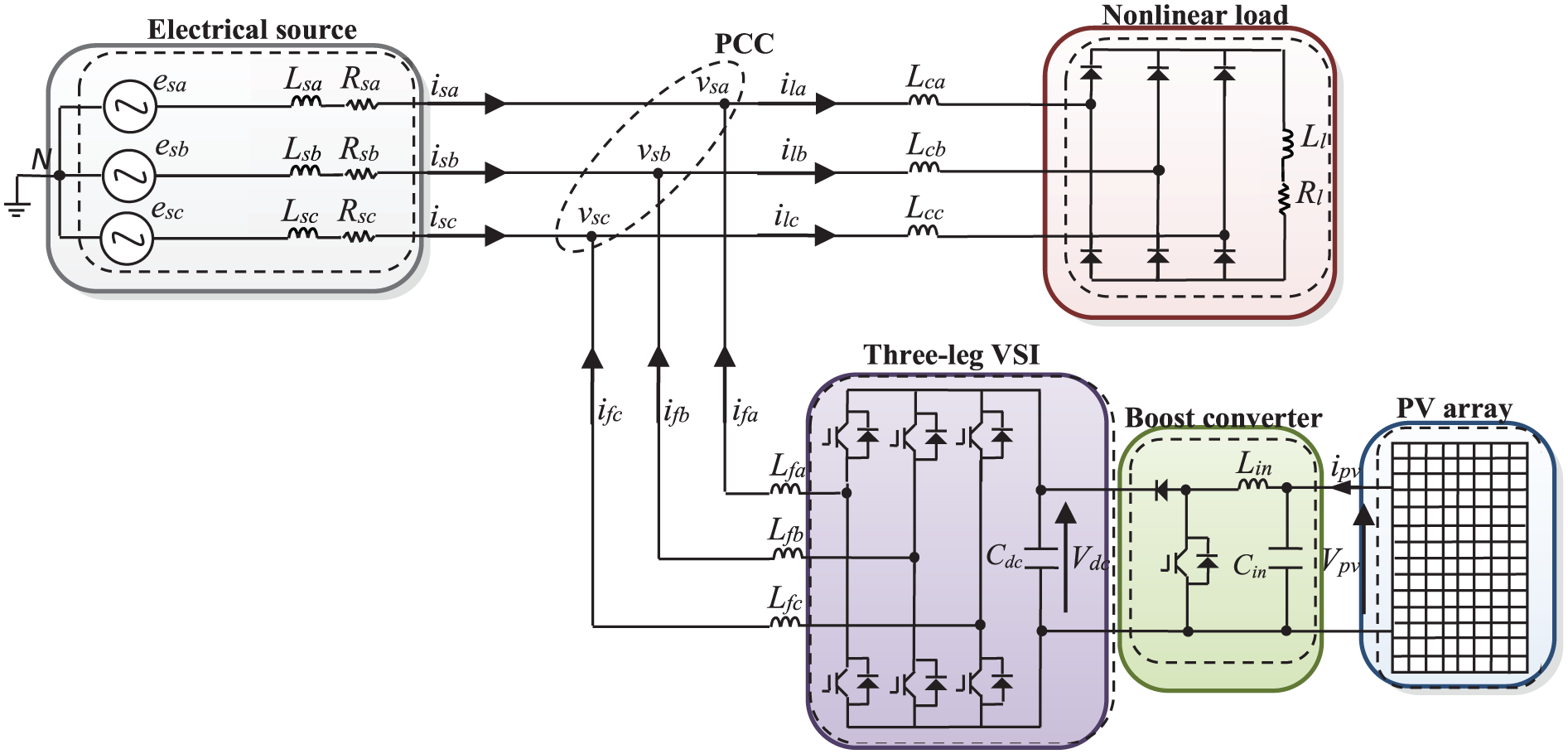
The structure of the grid-connected PV system.
The AC-side of a three-leg IGBT-based VSI is connected in parallel with the nonlinear load through a coupling inductor (
The PV array is composed of PV cells arranged in both series and parallel configurations. A PV cell is an electrical circuit that converts incident photons into electricity by the PV effect. The current-voltage curve of a PV cell can be obtained by the equation below.
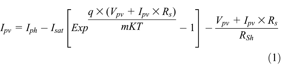
The PV cell provides an output current I pv and a photo-current I ph , with the output voltage V pv . The I sat is the current of saturation, K is the constant of Boltzmann, T is the temperature of the cell, q is the electron charge, and m is the factor of ideality (Miguel Álvarez et al., 2021; Mujammal et al., 2024; Tali et al., 2018).
The nonlinear power-voltage characteristic of a PV cell has a unique maximum power point (MPP). The boost converter is controlled to track the MPP of the PV array, and this power highly depends on solar irradiation and temperature. This maximum power is then transferred to the grid through the VSI of the SAPF.
The operating principle of SAPF is to generate harmonic currents that have an equal magnitude but are opposite in phase to those produced by nonlinear loads (Boukezata et al., 2016). Consequently, the SAPF ensures that the source current remains sinusoidal (Bekakra et al., 2021) while also compensating the load’s reactive power.
Proposed Adaline-based DPC
In this work, the VSI control includes identifying reference current using Adaline, calculating the reference active and reactive powers, controlling the DC bus voltage by a PI controller, and finally generating the switching patterns using the DPC.
Reference current identification
Consider the nonlinear load current of one phase (
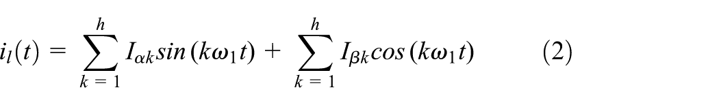
The
The Adaline estimates the load current
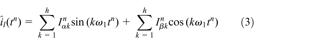
The vector form of

Where:
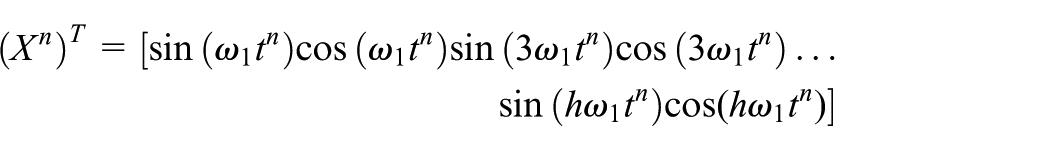
The
The input vector
The higher harmonic order h is selected based on the dominant harmonics generated by the nonlinear load. As mentioned in “System structure,” the system under study is a three-phase system with a rectifier-type nonlinear load. According to IEEE 519-2014, the lowest-order odd harmonics are usually the most significant in such load types, while higher-order components have negligible magnitudes. Therefore, the value of h = 19 is chosen to ensure that all significant harmonics are included, while maintaining a reasonable update time for the weights vector (
The weights vector

The η is the learning rate. Research studies indicate that increasing η accelerates convergence but at the cost of reduced accuracy and larger overshoots in the transient response. From a theoretical perspective, a dynamic η offers superior convergence characteristics; however, its implementation is more complex and necessitates a more sophisticated and costly hardware setup (Han et al. (2008)). Hence, in this study, η is obtained by trial and error.
The

To identify harmonic and reactive currents, the reference current is:

The
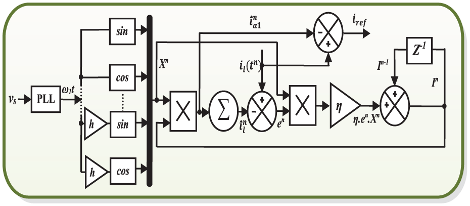
The structure of an Adaline.
Calculation of reference powers
Figure 3(a) and (b) show the schematic diagram of reference powers calculation using the conventional p–q and SRF methods, respectively, while Figure 3(b) presents the proposed approach. The proposed approach contains two loops. The first loop is depicted by three Adalines. It permits identifying the currents

The second loop contains a PI controller. This controller is added to maintain the DC link voltage (V
dc
) at its reference (

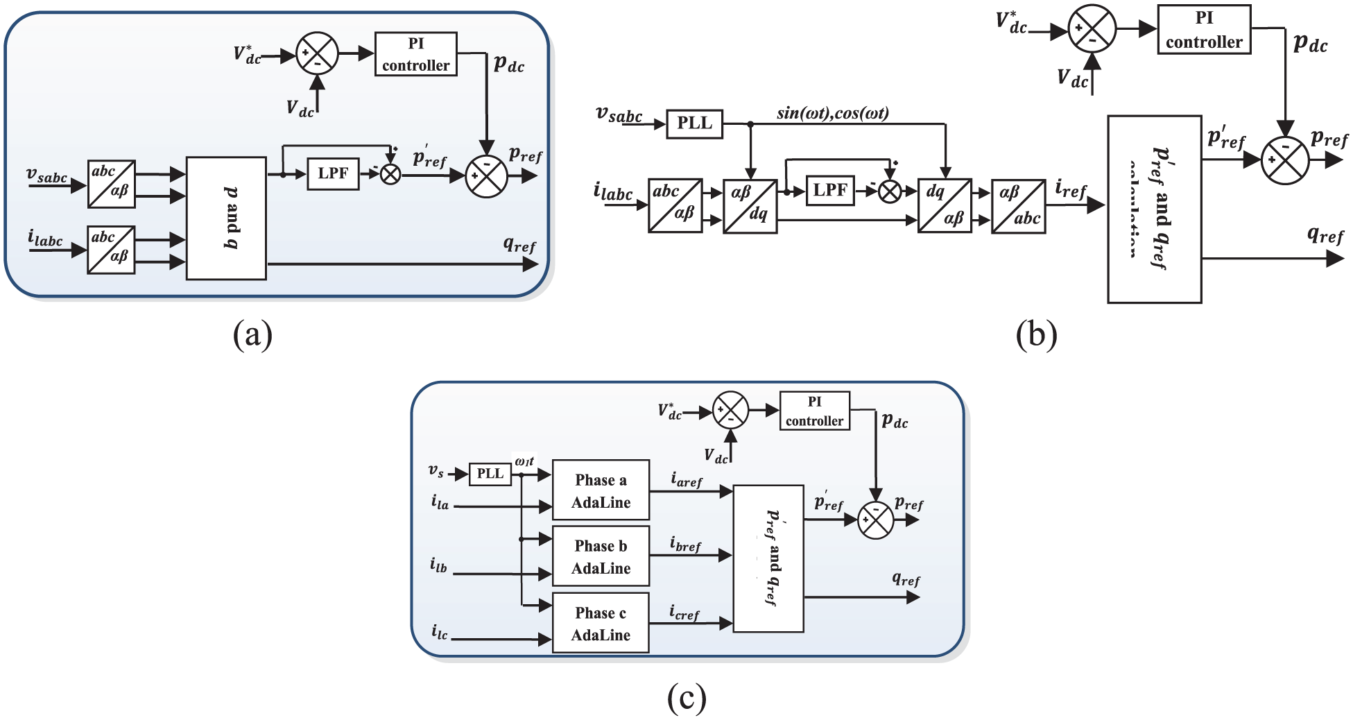
Diagrams of reference powers generation: (a) p–q method, (b) SRF method and (c) proposed method.
Generation of control signals
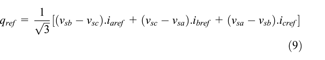
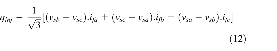
The active and reactive powers injected into the grid by the VSI are calculated from the voltages of the PCC and the filter currents as mentioned below:

The objective is to minimize the errors


After comparing the injected powers to their references, two-level hysteresis comparators are used to generate binary signals S p and S q , where:

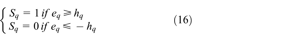
The
The outputs S
p
and S
q
, along with the sector index (
The switching table gives the output voltage vectors (Mesbahi et al., 2014).
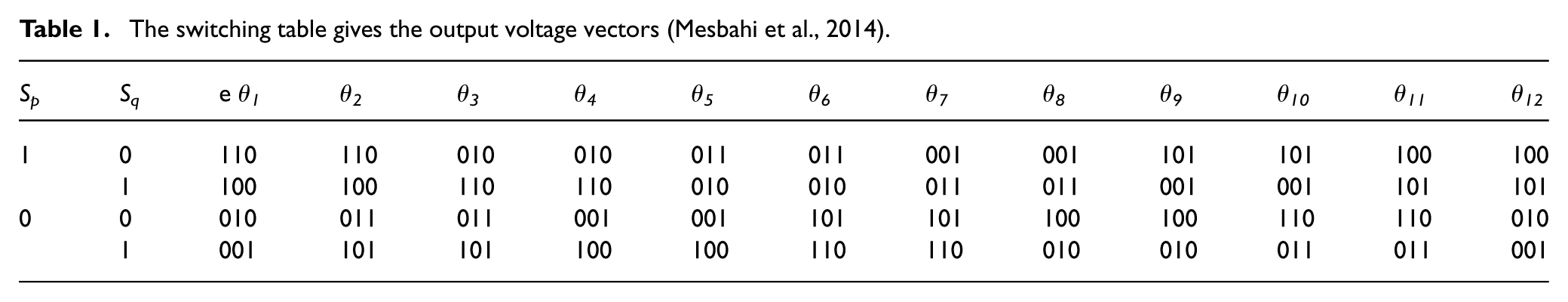
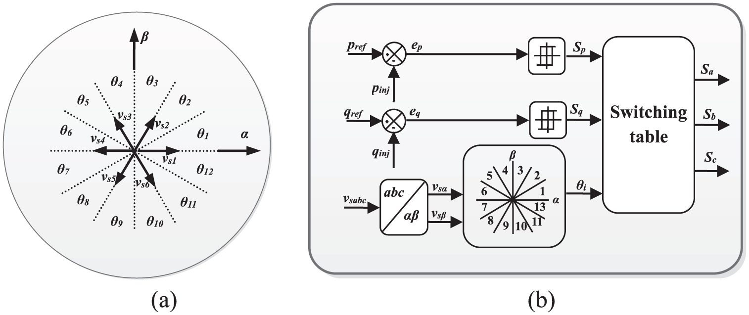
Control system elements: (a) Sectors on the αβ coordinates and (b) generation of the switching patterns with the DPC.
Simulation results
To evaluate the performance and robustness of the proposed approach, diverse simulations are done in MATLAB/Simulink.
The system parameters outlined in this study, which describe the electrical and control components of the proposed system, are as follows. The electrical source operates at 100 V and 50 Hz, with a resistance (Rs) of 0.42 mΩ and an inductance (Ls) of 2.3 μH. On the AC side of the load, the inductance (Lc) is 1 mH. The VSI features a coupling inductance (Lf) of 3 mH. The DC link capacitor has a capacitance (Cdc) of 1100 μF. The linear load is a three-phase start-connected system, where each phase contains a resistance (R) of 5 Ω in series with an inductance (L) of 0.5 mH. The nonlinear load (Load 1) is a three-phase rectifier with a higher DC side resistance (Rl) of 15 Ω in series with an inductance (Ll) of 3 mH. The boost converter includes an input capacitor (Cin) of 100 μF and an input inductance (Lin) of 5 mH. The PV array used is SunPower SPR-305-WHT, with two parallel strings and two series modules.
The DC link capacitor has a reference voltage (Vdc) of 300 V. A PI controller is used to regulate this DC link voltage, configured with a proportional constant (kp) of 0.2932 and an integral constant (ki) of 39.0836. The incremental conductance is used for the MPP tracking of the PV system, and the PWM is used to control the boost converter. The MPP of the array is 1.22 kW when the voltage is 109.4 V at an irradiance of 1000 W/m2. In addition, the Adaline component has a learning rate (η) set to 0.001, while the sample time (Ts) is 1 µs.
These parameters collectively define the electrical characteristics and control settings of the simulated grid-connected PV system. Note that in the simulation results, only the current waveforms of Phase A are represented, since the studied system is a balanced three-phase system.
Shunt active power filter mode
In this part, the PV array does not receive any irradiation; hence, the PV system works as SAPF. The aim is to test this SAPF’s performance in compensating for harmonic current and reactive power. The test also includes the moments of SAPF insertion to the grid and load variation.
Figure 5 shows the load current, the source current, and the current injected by the SAPF. The load is varied between 0.2 s and 0.3 s. The load current is nonsinusoidal due to the nonlinear load. It has a THD of 25.93% for Load 1 and 23.92% for Load 2. The source current becomes sinusoidal after the insertion of the SAPF at 0.1 s. It remains sinusoidal even when the load changes. The source current achieved a THD of 1.70% with Load 1 and 2.57% with Load 2.
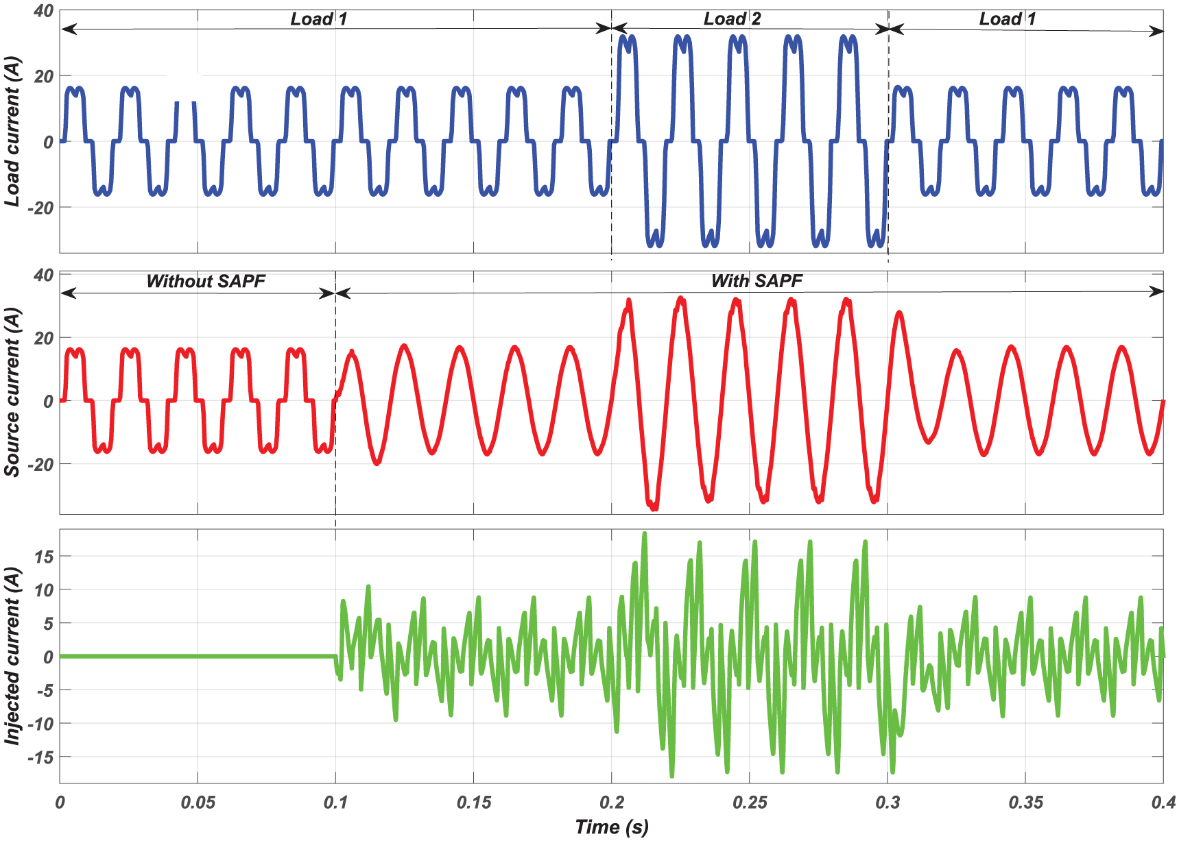
Load, source and injected currents under SAPF insertion and load variation.
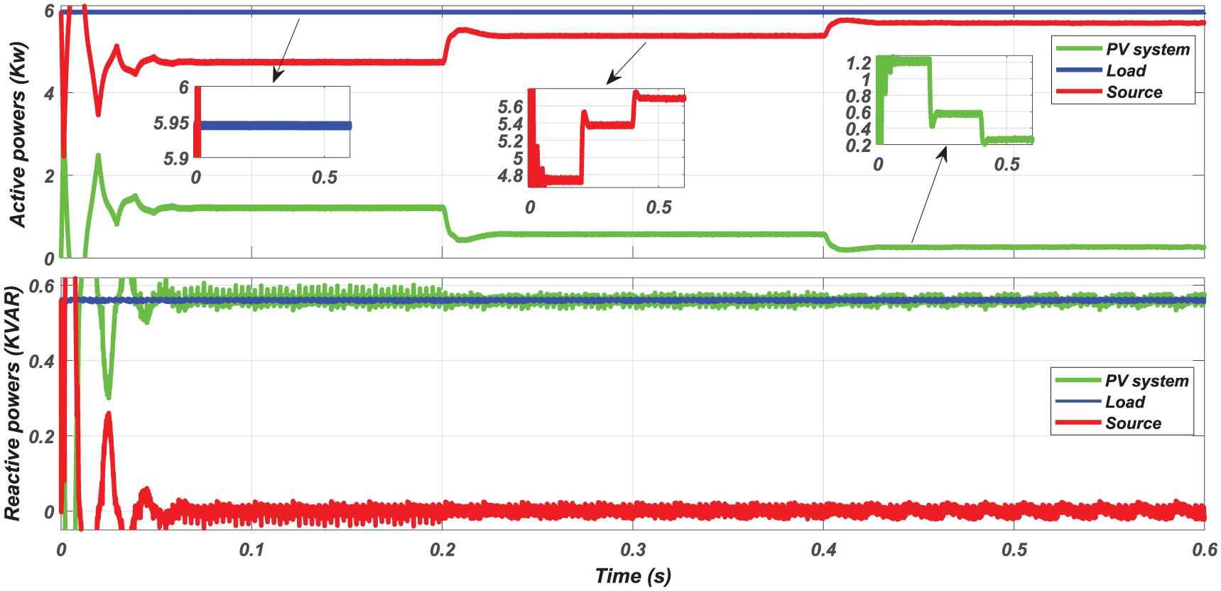
Figure 6 presents the active and reactive powers of the SAPF, load, and source. From 0.1 seconds, the moment of the SAPF insertion, the active power of the source becomes practically constant (P s = 3.55 kW for load 1 and P s = 6.70 kW for Load 2). The reactive power of the source reaches 0 from 0.1 seconds, which indicates that the reactive power is effectively compensated by the SAPF.
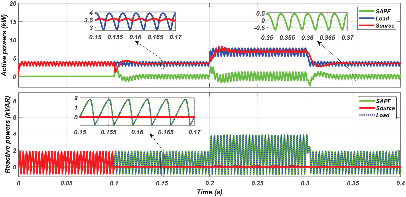
Active and reactive powers under SAPF insertion and load variation.
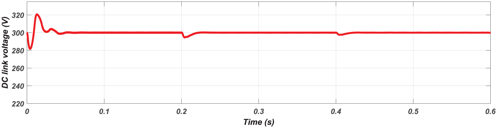
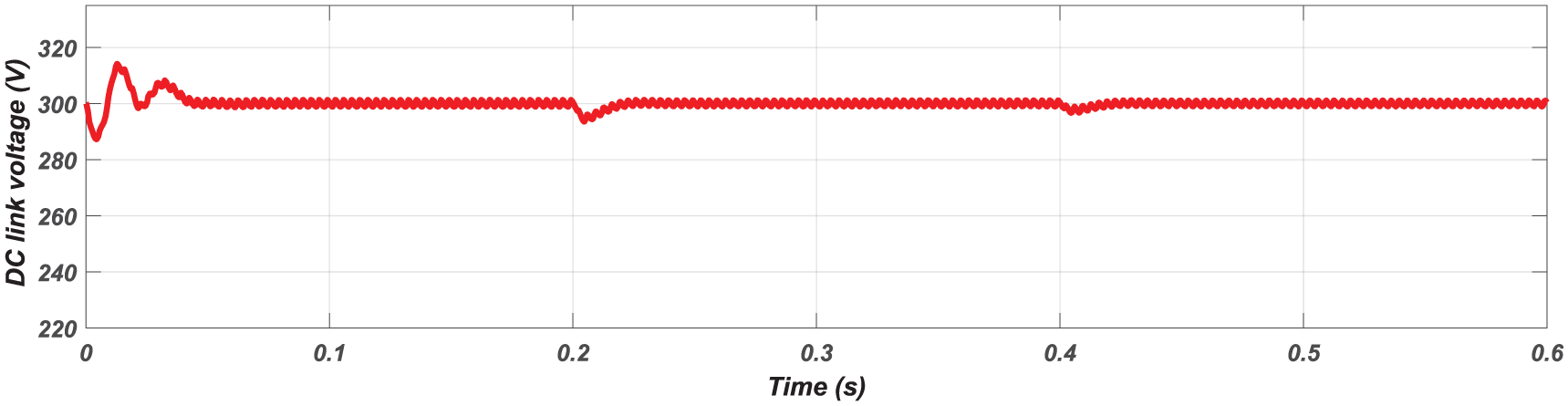
Figure 7 shows the DC bus voltage control with the PI controller. After the transient states related to the SAPF insertion and to the load variations, the voltage follows perfectly its reference value of 300 V. The results in this section highlight the effectiveness of the ADPC control in reducing the THD and compensating reactive power under load variations.
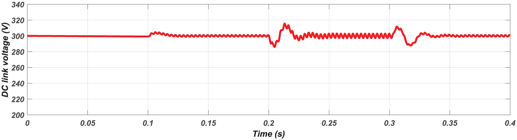
The DC link voltage under SAPF insertion and load variation.
Grid-connected PV system mode
This section presents and discusses the simulation results of the complete grid-connected PV system under both linear and nonlinear load conditions. These simulations are made to test the PV system’s performance in delivering active power to the grid and compensating harmonic current and reactive power of the load. The irradiance is variable in these simulations: it is equal to 1000 W/m2 from 0 to 0.2 seconds, it is 500 W/m2 from 0.2 to 0.4 seconds, and it is 250 W/m2 from 0.4 to 0.6 seconds.
Case of linear load
Figure 8 shows the source and the load currents. It is evident that the magnitude of the source current is less than that of the load current due to the energy transfer from the PV system to the grid.
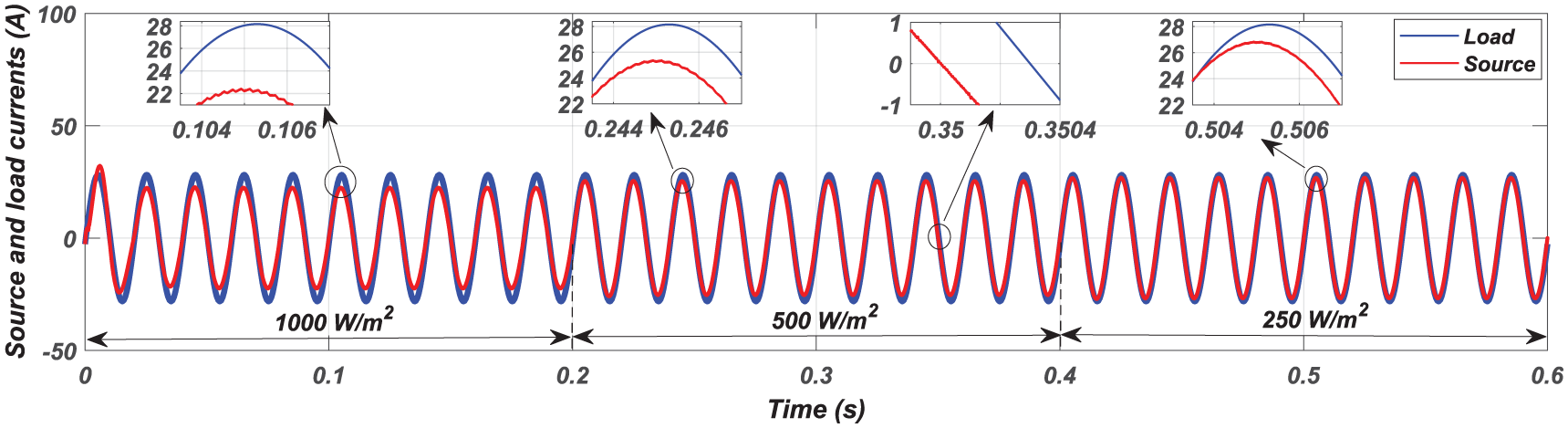
Source and load currents with linear load under variable irradiance conditions.
Figure 9 shows the active and reactive powers of the load, the source, and those injected by the PV system. The energy transfer from the PV system to the grid is clear, as the source active power is less than the load active power. The influence of the irradiance is also clear: when the irradiance is high, the energy transfer is greater, and conversely. The reactive power of the load is fed by the PV system, while the reactive power of the source remains null. Also, a good performance of the DC bus voltage control is demonstrated in Figure 10.
Active and reactive powers with linear load under variable irradiance conditions.
The DC link voltage with a linear load under variable irradiance conditions.
Case of nonlinear load
Figure 11 shows the source and the load currents. It demonstrates that the source current becomes sinusoidal and that it has a lower magnitude than the distorted load current due to the energy transfer from the PV system to the grid. The THD of the source current across varying irradiance levels is measured: at an irradiance of 1000 W/m2, the THD achieved a value of 2.60%. Similarly, at 500 W/m2, the THD values were 2.10%. Under lower irradiance conditions of 250 W/m2, the THD of 1.85% is obtained.
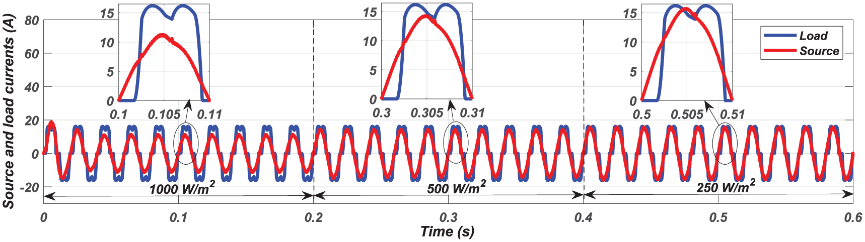
Source and load currents with nonlinear load under variable irradiance conditions.
Figure 12 illustrates the active and reactive powers of the load, the source, and those injected by the PV system. The energy transfer from the PV system to the grid is evident, as the source active power is always lower than the load active power. The effectiveness of active filtering is also clear, since in all three irradiation cases, the instantaneous active power of the source remains practically constant: P (1000 w/m2) = 2.3 kW, P (500 w/m2) = 2.95 kW, and P (250 w/m2) = 3.25 kW. The influence of the irradiance is also clear; when the irradiance is high, the energy transfer is larger, and the active power of the source is smaller, and conversely. Regarding the reactive powers, the source reactive power becomes practically null, as the PV system effectively compensates the reactive power of the nonlinear load. Figure 13 demonstrates the good regulation of the DC bus voltage, where
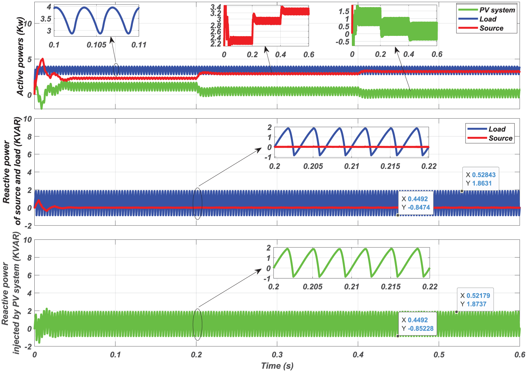
Active and reactive powers with nonlinear load under variable irradiance conditions.
DC link voltage with nonlinear load under variable irradiance conditions.
These results indicate the high performance of the PV system with ADPC control strategy in delivering active power to the grid and compensating harmonic currents and reactive power of the load under variable irradiance conditions.
Performance test of the ADPC under nonideal conditions
To demonstrate the superiority of the SAPF mode of the PV system with the ADPC over conventional control strategies, diverse simulations are conducted. The obtained results are compared, in the same conditions, with the following control strategies:
Conventional instantaneous active and reactive power control with DPC (CDPC),
HSF instantaneous active and reactive power control with DPC (HSFDPC) proposed by Mesbahi et al. (2014),
Conventional SRF control with DPC (SRFDPC), and
HSFSRF control with DPC (HSFSRF-DPC).
The operating conditions considered in this part are as follows:
Phases B and C, as mentioned in Table 2.
Simulation results under different conditions.
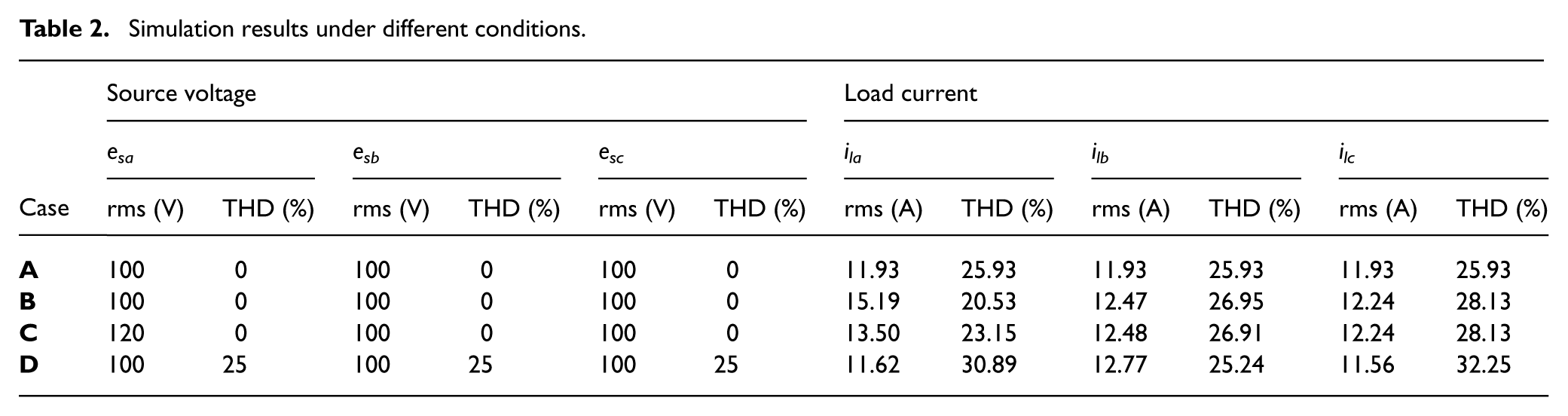
The results of simulations are summarized in the tables below. Table 2 presents the source voltage and the load current results under the four cases mentioned above. It can be noted that in all cases the THDs of the load current do not respect the IEEE-519 limits of 5%. The analysis of the four cases according to the simulation results is below:
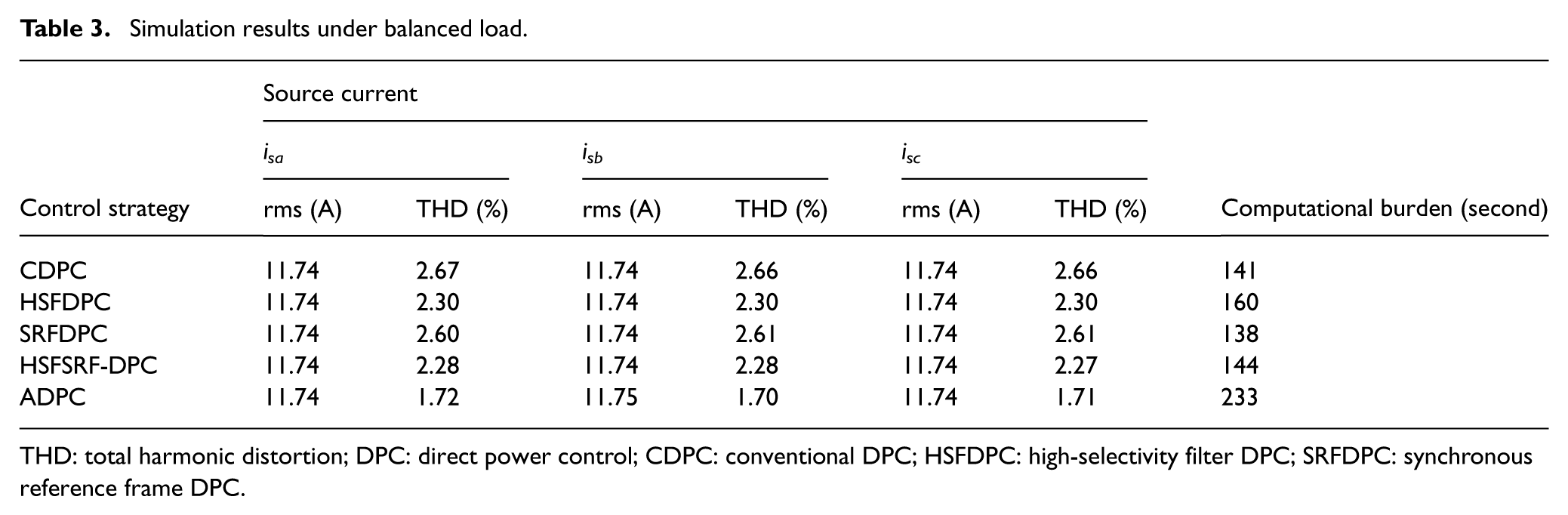
Simulation results under balanced load.
THD: total harmonic distortion; DPC: direct power control; CDPC: conventional DPC; HSFDPC: high-selectivity filter DPC; SRFDPC: synchronous reference frame DPC.
Simulation results under unbalanced load.

THD: total harmonic distortion; DPC: direct power control; CDPC: conventional DPC; HSFDPC: high-selectivity filter DPC; SRFDPC: synchronous reference frame DPC.
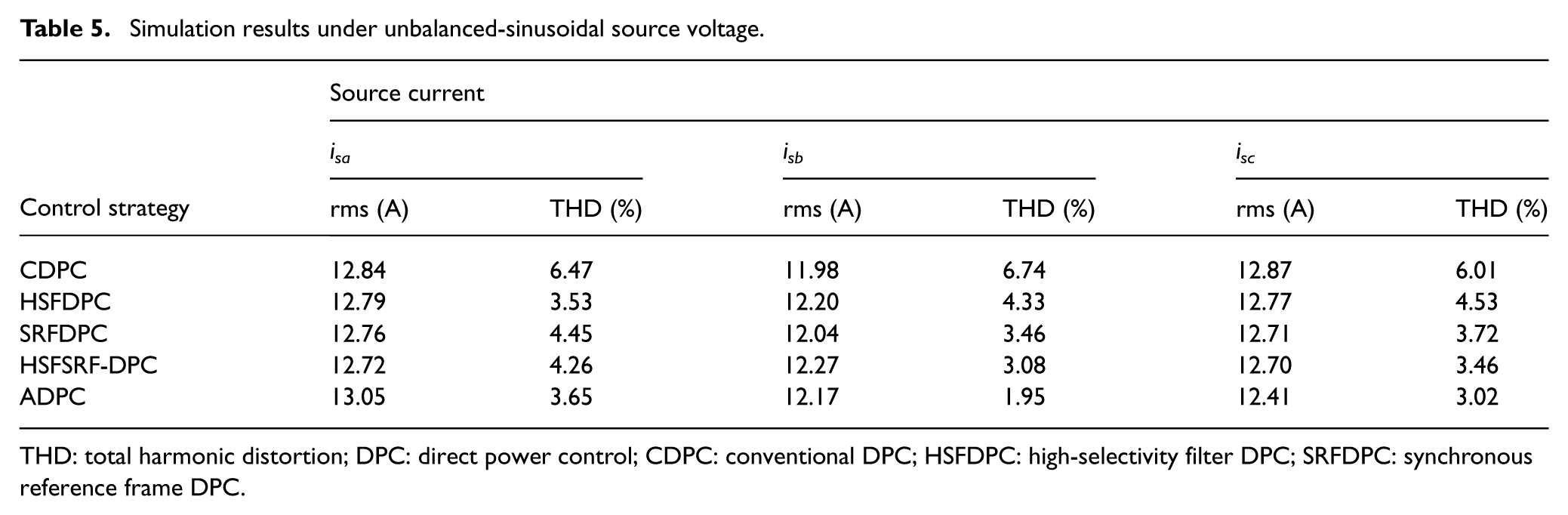
Simulation results under unbalanced-sinusoidal source voltage.
THD: total harmonic distortion; DPC: direct power control; CDPC: conventional DPC; HSFDPC: high-selectivity filter DPC; SRFDPC: synchronous reference frame DPC.
Simulation results under balanced-distorted source voltage.
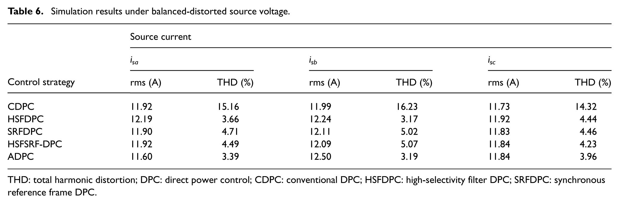
THD: total harmonic distortion; DPC: direct power control; CDPC: conventional DPC; HSFDPC: high-selectivity filter DPC; SRFDPC: synchronous reference frame DPC.
The simulation results of the above-mentioned cases demonstrate that the ADPC reduces the current THDs to below 5%, which indicates that the Adaline used in the ADPC permits it to outperform the other tested control strategies in reducing the harmonic distortion.
Conclusion
This study proposed a PV-grid-connected SAPF system controlled by ADPC, where the VSI functions as a multipurpose device, converting energy to the grid and simultaneously reducing harmonic currents, as well as acting as a reactive power compensator. Divers’ simulations were conducted with different configurations. The first configuration is the SAPF mode, in which the performance of harmonic and reactive currents mitigation during the load variation is evaluated. The second is the complete grid-connected PV system mode, where the system is first tested with a linear load to study the PV system’s capacity of energy transfer to the grid. Then, the system is tested with a nonlinear load under different irradiations to evaluate its capacity for energy transfer to the grid and its ability to mitigate harmonic and reactive currents. Finally, to validate the performance of the ADPC, their THD and computational burden are compared with those of CDPC, HSFDPC, SRFDPC, and HSFSRF-DPC under both ideal and nonideal conditions.
The simulation results highlight the effectiveness of the proposed hybrid ADPC in reducing the THD under load variations and various irradiance levels. Although it involves a relatively higher computational burden, ADPC outperforms CDPC, HSFDPC, SRFDPC, and HSFSRF-DPC by achieving superior harmonic reduction performance under both ideal and nonideal operating conditions.
Footnotes
Acknowledgements
There is no acknowledgment involved in this work.
Author contributions
T.M., M.N., M.R., and N.M. contributed to conceptualization. T.M., M.N., and N.M. contributed to methodology. T.M., M.R., and N.M. contributed to formal analysis and investigation. T.M., M.N., M.R, and N.M. contributed to writing—original draft preparation. T.M., M.N., and N.M. contributed to supervision.
Funding
The authors received no financial support for the research, authorship, and/or publication of this article.
Declaration of conflicting interests
The authors declared no potential conflicts of interest with respect to the research, authorship, and/or publication of this article.
Data availability statement
Data sharing is not applicable to this article, as no datasets were generated or analyzed during the current study.