
Abstract
Autonomous hydraulic excavators are widely used in construction, mining, and material-handling operations, offering improved efficiency and safety. Precise trajectory tracking is essential for such systems. However, inherent nonlinearities and significant time delays in the hydraulic actuators hinder accurate control for autonomous operations. To address these challenges, a nonlinear model predictive control (NMPC) algorithm is proposed. Specifically, a Hammerstein–Wiener structure is employed to model the nonlinear hydraulic system, with parameters identified from experimental data. Based on this model, an NMPC trajectory-tracking algorithm is developed, which accounts for actuator and control input constraints. To mitigate the intrinsic 0.5-second response delay of the hydraulic system, a predictive delay compensation strategy is introduced, whereby predicted joint states over the next 0.5 seconds serve as real-time control references. Simulation results demonstrate that the proposed controller substantially outperforms proportional–integral–derivative (PID) and fuzzy PID methods, maintaining the bucket-end error within 20 cm. Field experiments on an autonomous excavator implemented under the robot operating system (ROS) framework confirm that the maximum trajectory-tracking error remains within 50 cm, validating the effectiveness and robustness of the proposed NMPC approach under real-world operating conditions.
Keywords
Introduction
Hydraulic excavators are indispensable heavy machinery in earthmoving and infrastructure development, with applications in agricultural reclamation, mining, and urban construction. Their performance directly impacts construction efficiency, safety, and project quality. For large-load hydraulic excavators, in particular, the inherent strong nonlinear hydraulic dynamics, significant actuation time delays, and complex multi-body coupling effects pose great challenges to trajectory tracking control. Conventional proportional–integral–derivative (PID) controllers and their improved variants often fail to achieve satisfactory tracking performance under such conditions, due to their inability to effectively handle the aforementioned nonlinearities and time delays—this constitutes the primary motivation for this research.
To address these control challenges, extensive research has advanced autonomous excavator technologies, including dynamic modeling (Cao and Xie, 2018; Vähä and Skibniewski, 1993; Xu and Yoon, 2016), trajectory planning (Ding et al., 2024; Jin et al., 2024; Zhang et al., 2017), trajectory tracking (Fan et al., 2024; Feng et al., 2018), and energy optimization (Yang et al., 2023; Yu et al., 2021). In the domain of trajectory tracking, classical PID controllers are widely used for their simplicity, with improvements via fuzzy adaptive tuning (Ma et al., 2023; Zhang et al., 2009) and metaheuristic optimization (e.g. ant colony optimization (ACO)) (Dong et al., 2024; Hassan and Sugban, 2018; Xia, 2020). Recent research has further explored intelligent PID-based control strategies for autonomous vehicles and mobile robots. For instance, a fuzzy-immune-regulated single-neuron adaptive PID controller has been developed to enhance trajectory tracking robustness for a lawn-mowing robot under environmental disturbances and nonlinear coupling effects (Saleem et al., 2024). Such approaches demonstrate improved adaptability and disturbance rejection in relatively lightweight nonholonomic systems. Recent studies have proposed advanced nonlinear and intelligent control strategies, including adaptive fault-tolerant, data-driven, and model-free approaches, to improve robustness and adaptability under uncertainties, actuator faults, and external disturbances (Bey and Chemachema, 2024; Bey et al., 2025; Moon et al., 2025). However, these methods are primarily developed for relatively low-inertia robotic or wearable systems, and they remain inadequate for large-load hydraulic excavators due to strong nonlinearities, time-varying parameters, dead zones, inherent delays, and the lack of predictive optimization and constraint-handling capabilities.
Nonlinear model predictive control (NMPC) has emerged as a promising solution for complex nonlinear systems, as it can handle multivariable systems, enforce physical constraints, and account for nonlinear dynamics within a unified online optimization framework (Chen et al., 2021; Wang et al., 2023; Zavala and Biegler, 2009). This enables the trajectory tracking problem to be formulated as a constrained finite-horizon optimal control problem (FHOCP) (Han et al., 2024), facilitating systematic management of actuator limits and system uncertainties.
To effectively address the trajectory tracking challenges of large-load hydraulic excavators, this study proposes a comprehensive NMPC-based trajectory tracking framework implemented through a complete process: first, a multi-objective particle swarm optimization (MOPSO) algorithm is employed to generate joint-space reference trajectories that balance motion efficiency and energy consumption (Huang et al., 2023; Peng et al., 2024), providing a feasible and optimal motion reference for subsequent tracking control. Second, a Denavit–Hartenberg (D–H) kinematic model (Denavit and Hartenberg, 1955) is used to transform joint angle commands into hydraulic cylinder displacement signals, ensuring the generated trajectories are physically compatible with actuator stroke limits and practical operation requirements. A nonlinear Hammerstein–Wiener model is embedded into the NMPC formulation to fit and describe the nonlinear dynamics of the hydraulic system, enabling more accurate capture of the hydraulic system’s nonlinear characteristics and time delays compared to simplified hydraulic models used in prior related studies. Within the NMPC framework, system constraints (including actuator saturation, pressure limits, and velocity bounds) and tracking errors are unified within a quadratic cost function, and the resulting constrained finite-time optimal control problem (FTOCP) is solved iteratively via a receding-horizon strategy to achieve real-time compensation for model uncertainties and external disturbances. This integrated framework ensures superior trajectory tracking accuracy, robustness, and adaptability compared to conventional PID and fuzzy PID control methods, specifically tailored to the characteristics of large-load hydraulic excavators.
To validate the efficacy and practicality of the proposed framework, a high-fidelity MATLAB/Simulink simulation model of the large-load hydraulic excavator is developed. Comparative trajectory tracking experiments are conducted using conventional PID, fuzzy PID, and the proposed NMPC controller, evaluating their performance across key metrics. Field experiments on a physical excavator platform further confirm the real-world applicability and engineering viability of the proposed control strategy. Beyond excavator automation, the proposed methodology is applicable to a wide range of real-world systems, including autonomous heavy machinery, mining equipment, robotic manipulators, and other hydraulic actuation systems operating under strong nonlinearities, large inertia, and time delays.
Experimental equipment
To experimentally validate the proposed trajectory tracking algorithm, a large-scale hydraulic excavator was selected as the research platform. Figure 1(a) illustrates the overall structure of the excavator; this model is designed for heavy-duty engineering applications, offering high reliability, strong adaptability, and flexible operational performance. Its advanced hydraulic control system and integrated sensor network provide an ideal testbed for verifying trajectory tracking algorithms.
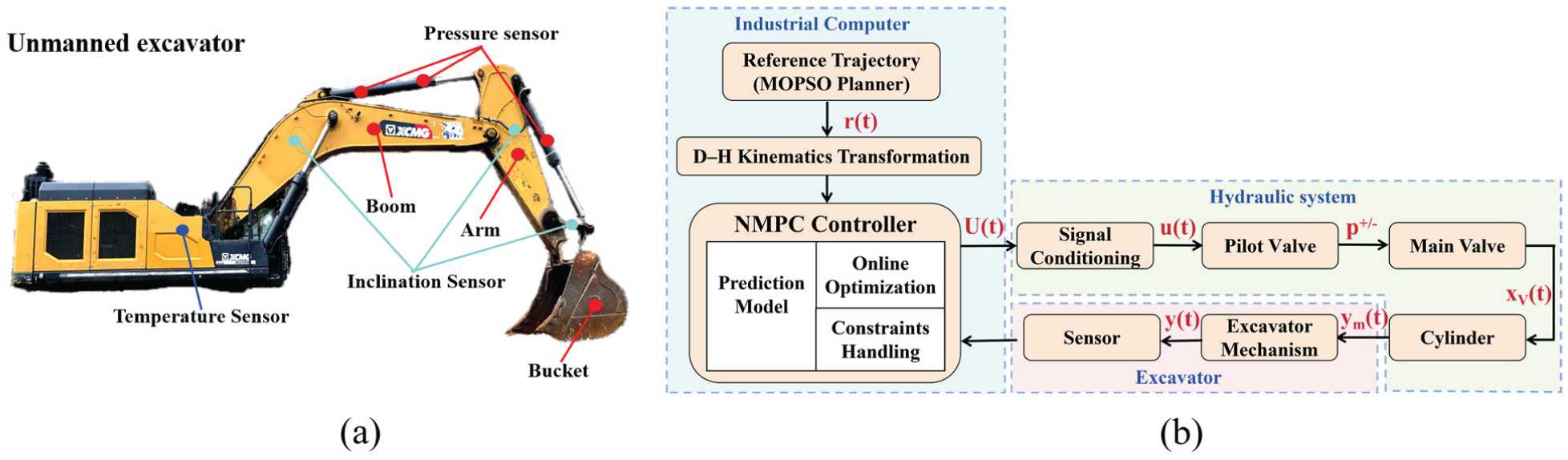
Overall structure of unmanned excavator and hydraulic execution control flow diagram of excavator. (a) Unmanned excavator experimental platform. (b) Trajectory tracking control system block diagram.
The control flow of the excavator’s hydraulic system, corresponding to the block diagram presented in Figure 1(b), is elaborated as follows. The working device of the excavator adopts an articulated structure composed of a boom, arm, and bucket, forming a multi-joint linkage mechanism. The industrial computer serves as the core control unit, and the entire control process adheres to the proposed NMPC-based framework: first, the reference trajectory r(t) is generated by the MOPSO planner in the joint space; subsequently, the D-H kinematics transformation module converts the joint angle information of the reference trajectory into cylinder displacement signals, which are then transmitted to the NMPC controller. The NMPC controller employs a nonlinear Hammerstein–Wiener model as the hydraulic prediction model and implements FTOCP based on the receding horizon strategy, while strictly satisfying constraints including actuator saturation, pressure limits, and velocity limits.
The NMPC controller outputs the control input U(t) according to the deviation between the planned trajectory and the feedback information. These control signals U(t) first undergo signal conditioning, which converts them into the control signal u(t). The signal u(t) is then transmitted to actuate the pilot valve, which further drives the main valve to output pressures p+/−, thereby controlling the hydraulic cylinder to produce the actual displacement x v (t). The hydraulic cylinders are directly connected to the boom, arm, and bucket, and their movements drive the excavator’s working device to complete the desired actions. The sensor system (equipped with displacement transducers, pressure sensors, etc.) continuously collects the measured output y m (t) from the cylinder, which is then converted to the actual trajectory y(t) of the excavator mechanism. This measured output y(t) is fed back to the NMPC controller to realize closed-loop control. The slewing mechanism, as the main support structure of the excavator, carries the powertrain and transmission components to ensure stable operation.
Hydraulic excavator modeling
To develop the NMPC controller, establishing a precise mathematical representation of the hydraulic excavator is critical. This section outlines the modeling of the excavator’s kinematics and hydraulic systems.
Kinematic model
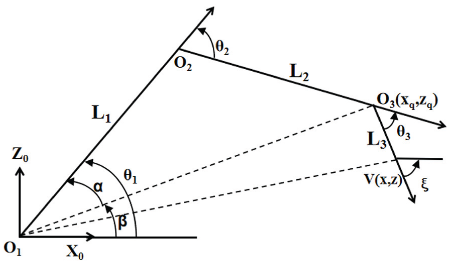
The working device of the excavator is simplified as a three-degree-of-freedom planar manipulator, consisting of the boom, stick, and bucket, with respective lengths L1, L2, and L3. Points O1, O2, and O3 denote the joints connecting the boom to the base, the boom to the stick, and the stick to the bucket, respectively, as shown in Figure 2. To map the desired end-effector trajectory of the bucket V(x, z) to the corresponding joint angles, the inverse kinematics must be solved under the constraint of a specified digging angle ξ of the bucket, ensuring the uniqueness of the solution. For real-time control systems, the computational cost of solving the inverse kinematics is relatively high. Therefore, a geometric approach is adopted, which is both intuitive and computationally efficient, particularly suitable for manipulators with a small number of degrees of freedom (Dong and Zhang, 2001; Ji, 2005; Li et al., 1998). The joint angle expressions are given as follows
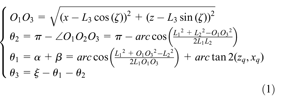
Here, θ i (i = 1–3) represents the angles of the boom with respect to the horizontal plane, the stick relative to the boom, and the bucket relative to the stick, respectively.
Simplified model of planar four DOFs manipulator.
Hydraulic system model
The excavator electro-hydraulic system primarily consists of an electro-hydraulic proportional valve and a valve-controlled asymmetric cylinder. The control signal u of the electro-hydraulic proportional valve is determined by the nonlinear value g js of the operating lever and the virtual handle signal U js

After signal conditioning, the signal u actuates the pilot valve to generate the differential pilot pressures p+/-, which in turn regulate the main valve spool displacement x v . The dynamics of the pilot valve can be approximated by a first-order system (He et al., 2008; Li et al., 2012)

where K is the proportional gain and T c is the valve time constant.
Neglecting valve leakage, the valve flow equation can be expressed as (Yang et al., 2007)
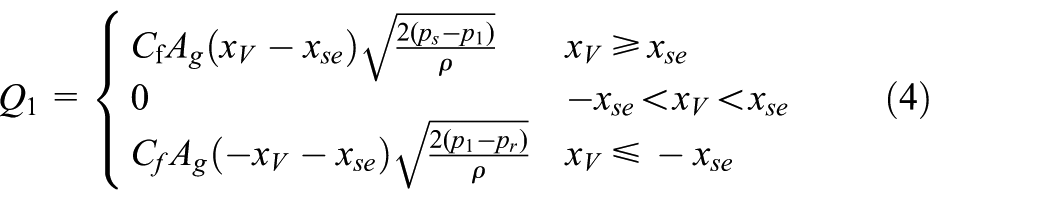
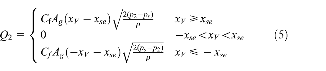
Let Q1 and Q2 represent the flow rates through the rodless and rod chambers of the hydraulic cylinder, respectively. The flow coefficient is denoted by C f , while A g refers to the gradient of the valve port area. The oil-seal stroke is indicated by x se . ρ stands for the hydraulic fluid density, p s is the inlet pressure, p r is the return pressure, and p1 and p2 are the pressures within the rodless and rod chambers, respectively.
For asymmetric hydraulic cylinders, the flow rates of the rodless and rods’ chambers are expressed as follows
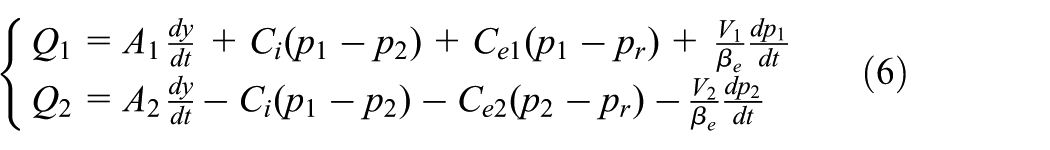
Here βe represents the effective volume elastic modulus, while C i , Ce1, and Ce2 denote the internal and external leakage coefficients. In addition, A1, A2, V1, and V2 are the effective areas and volumes of the rodless and rod chambers of the piston, respectively.
The dynamic behavior of the hydraulic cylinder, which drives the motions of the boom, arm, and bucket, can be described by the force equilibrium equation

where M is the equivalent mass reflected to the piston, B p is the effective damping coefficient, K f is the elastic stiffness, and F ext represents the external load acting on the cylinder.
Let the state variables
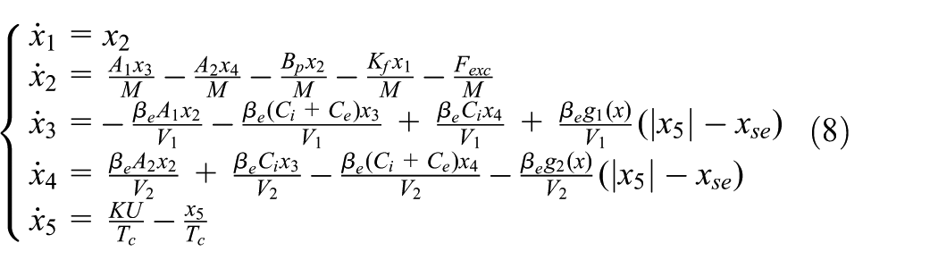
where g1(x) and g2(x) denote the nonlinear flow gains of the spool valve. The specific expressions for these gains are given by

By following these steps, the nonlinear state-space equations governing the excavator’s electro-hydraulic control system are established. However, in practical applications, accurately obtaining some parameters, such as the viscous friction coefficient B p and the equivalent load elastic stiffness K f , can be challenging. These parameters are influenced by various factors, including the characteristics of hydraulic oil, the wear of the hydraulic cylinder, and environmental temperature, making precise determination difficult through theoretical calculations.
Therefore, the hydraulic excavator model is simplified for the implementation of subsequent model predictive control. The simplification process is as follows. Let the state vector be
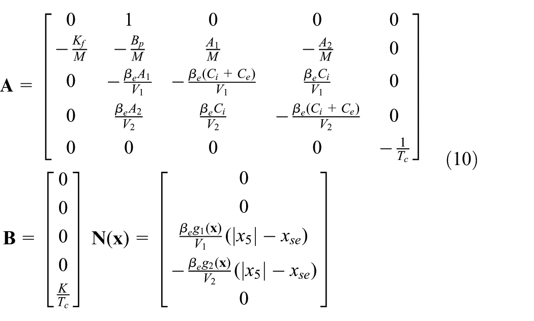
Combining the linear and nonlinear parts, the state equation is simplified as

The derived hydraulic system model conforms to the Hammerstein–Wiener structure (Bender et al., 2015), comprising two static nonlinear blocks and an intermediate linear dynamic system. We therefore adopted a system identification approach to fit the model parameters, with analog handle signals as inputs and measured hydraulic cylinder velocities as outputs.
Field tests were conducted at a mining site to acquire a rich training dataset: each manipulator link was actuated independently across its full stroke at varying speeds, with pilot pressure and joint angular velocity synchronously sampled at 10 Hz for 300 seconds, yielding ∼3000 samples per link. The raw data were preprocessed via Butterworth low-pass filtering, static bias correction (for sensor drift) and five-point moving-window smoothing (for vibration suppression), then split into 60% training and 40% validation subsets, with the Kolmogorov–Smirnov test (p > 0.05) confirming dataset consistency.
A piecewise linear function was selected for the static nonlinear blocks. Comparison of models with 0–5 segmentation points showed that R2 improvement dropped below 3% when the segment number exceeded 2; a single segmentation point was thus chosen to balance fitting accuracy and computational efficiency. The linear dynamic block was configured as a first-order numerator, third-order denominator transfer function, with a one-sampling-cycle input delay to account for the hydraulic system’s inherent lag. This configuration achieved optimal fitting performance for the excavator hydraulic system.
The final Hammerstein–Wiener model is formulated as follows
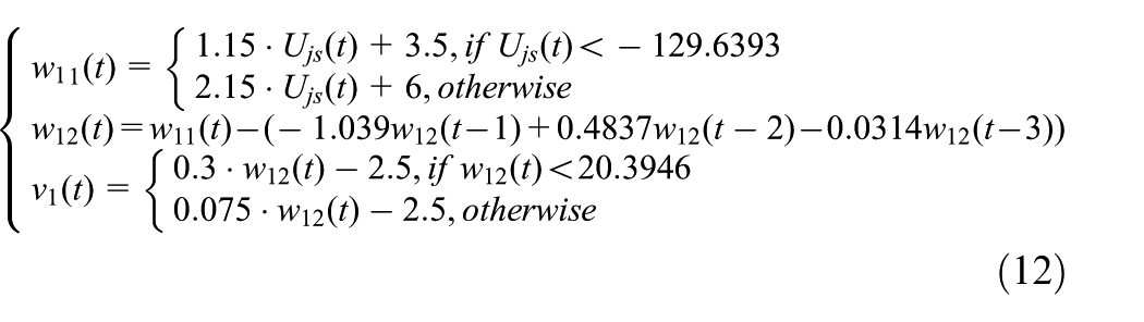
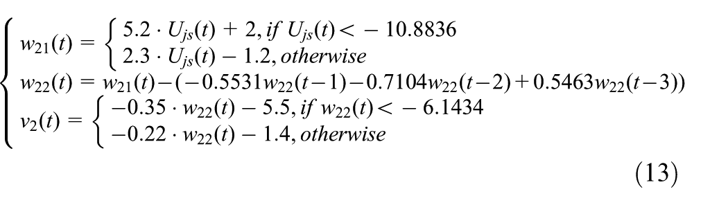
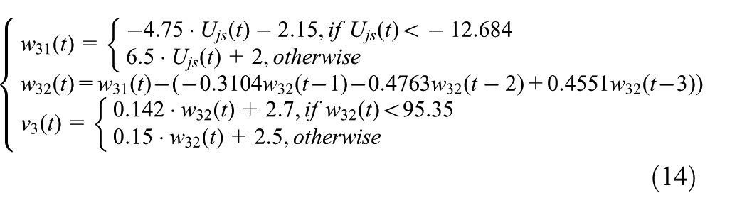
Here, w ij and v i (i = 1–3, j = 1–2) represent the intermediate variables and final output hydraulic cylinder velocities for the boom, arm, and bucket fitted models, respectively.
Figure 3 illustrates a comparison between the computed outcomes of the fitted models and the actual test data. The calculated determination coefficients for the three components are as follows:
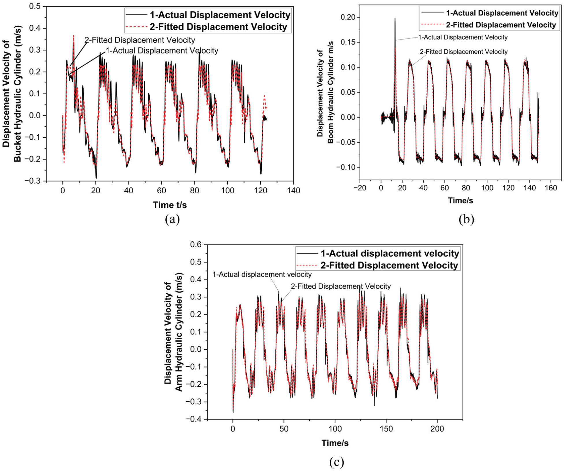
Fitting model versus test data for boom, arm, and bucket cylinders. (a) Boom cylinder. (b) Arm cylinder. (c) Bucket cylinder.
NMPC
The core of trajectory tracking control lies in regulating input signals to enable the manipulator’s joint angles to precisely follow the desired trajectory, while minimizing the tracking error under the premise of ensuring the stability of the closed-loop system.
The MPC controller integrates an Optimization Solver, an Objective Function & Constraints block, and a Prediction Model. The Prediction Model infers future system states based on the current state variables and manipulated variable. The Optimization Solver, guided by the Objective Function and system constraints, solves for the optimal control signal (Rawlings, 2000).
Design of control model
System dynamic model
The dynamic model of the hydraulic system fitted in the previous section can be expressed as
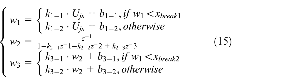
where k i−j (i = 1, 2, 3) represents the parameters obtained from the Hammerstein–Wiener model fitting, x break denotes the breakpoint of the piecewise nonlinear function.
Accordingly, the system state X(k) is updated as a function of the current state and the control input U js . The state transition equation is

where
Based on the nonlinear state transition model, future system states over the prediction horizon are recursively generated from the current measured state. At time step k, the predicted states are computed as

where N p denotes the prediction horizon. This recursive prediction process produces the future state trajectory used in the optimization problem. At each sampling instant, only the first control input of the optimized sequence is applied to the system according to the receding-horizon strategy.
Objective function
To determine the optimal control input U js , the prediction model is formulated as a nonlinear programming problem (Qi and Jiang, 2021)
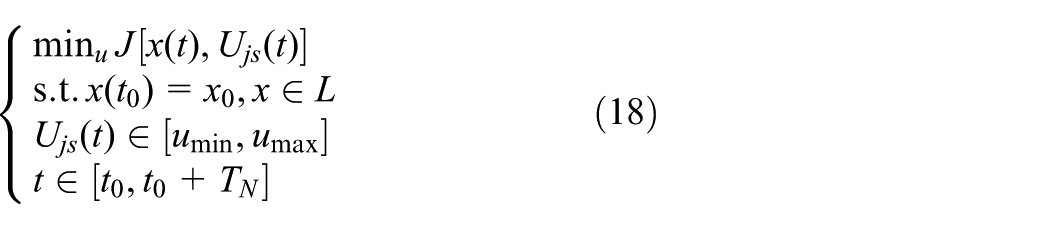
where L constrains the displacement and velocity of the hydraulic cylinder based on the actual excavator model parameters;
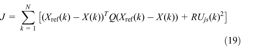
where X(k) represents the system state (including the position and velocity of the hydraulic cylinder) at time k, X ref (k) denotes the reference trajectory generated by the trajectory planning module, Q and R are weight matrices, and U js (k) is the control input of the virtual handle signal.
Optimization of the NMPC problem
The optimization problem described above is solved iteratively using the gradient descent method, a widely employed numerical optimization technique. By iteratively updating the control inputs and system states along the negative gradient of the cost function, the algorithm gradually converges to the optimal solution.
Lagrangian function
To account for the constraint conditions, the Lagrange multiplier method is introduced. The Lagrangian function incorporates both the cost function J and the constraint conditions. Specifically, the form of the Lagrangian function is given by
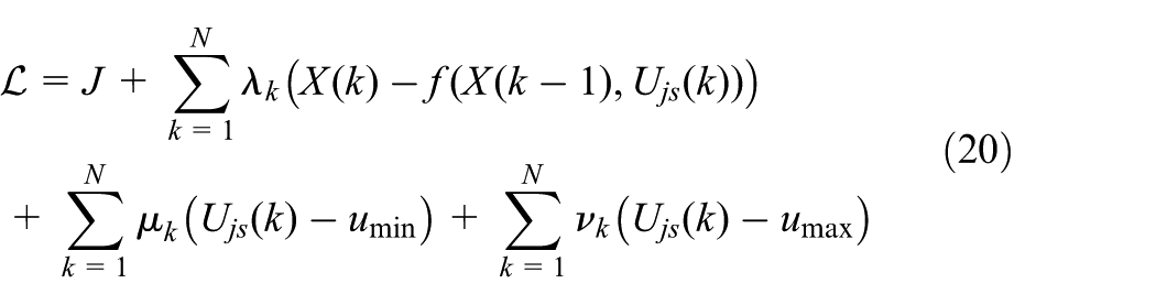
where λ k denotes the Lagrange multiplier linked to constraints on system dynamics, reflecting the influence on the system state; μ k and v k represent the Lagrange multipliers corresponding to control input constraints, indicating the impact on the control input limits.
Gradient calculation and iterative update by gradient descent method
The gradients of the Lagrangian function with respect to the control input U js (k) and the state X(k) are calculated. The control input and system state are updated according to the following rules
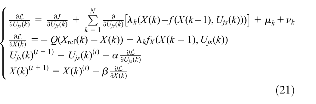
where
Real-time implementation and constraints
The NMPC controller adopts a five-step prediction horizon, forming a fixed-dimensional finite-horizon optimization problem. This value is determined via extensive simulation and field tests to achieve the optimal balance between control performance and computational efficiency: a longer horizon improves tracking accuracy but increases computational load, while a shorter horizon reduces computation time at the cost of degraded control effectiveness. Under the receding-horizon principle, only the first element of the optimized control sequence is applied at each sampling instant, ensuring high responsiveness to disturbances and model mismatches without accumulating computational complexity. The controller runs with a 0.1-second sampling period, and each optimization iteration takes approximately 0.01 seconds—far shorter than the control update interval—verifying that the proposed scheme fully satisfies the real-time implementation requirements of the unmanned excavator system. To ensure safe and smooth operation, three key physical constraints are explicitly embedded in the NMPC formulation: the control input is bounded to [−1000, 1000] to match actuator limits, joint angular velocity is constrained below 10°/second to avoid excessive motion, and the control signal change rate is limited to 50 per step to suppress mechanical oscillations. These constraints collectively guarantee stable and physically feasible trajectory tracking.
Simulation results
A high-fidelity simulation platform of the excavator manipulator was established for algorithm validation, based on the physical machine’s structural parameters. A detailed 3D assembly model was built in SolidWorks and imported into Simulink, with revolute joints for link connections, prismatic joints for hydraulic cylinders, and nonessential components (cab, chassis) excluded to optimize computational efficiency (Figure 4(a) and (b)). Field data analysis identified an inherent 0.5-second actuation delay in the hydraulic system, which significantly degrades tracking accuracy. To address this, a 0.5-second predictive advance compensation strategy is integrated into the NMPC framework: the joint angles and angular velocities over the next 0.5 seconds are predicted via dynamic forward solution, and used as the real-time control reference to offset the hydraulic lag. The complete control system flowchart is shown in Figure 4(c). Two sets of simulation tests were conducted to comprehensively evaluate the proposed algorithm: standard signal tracking for fundamental dynamic performance validation, and practical excavation trajectory tracking for task-oriented applicability verification.
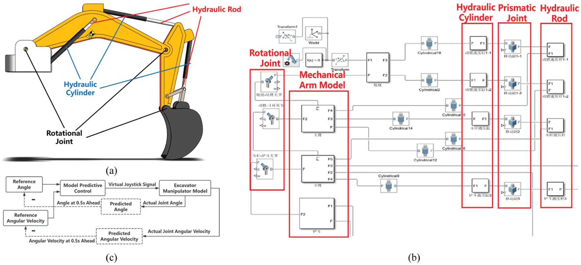
Simulation platform based on SolidWorks and Simulink and NMPC control block diagram (with 0.5-second advance control). (a) Excavator assembly model in SolidWorks. (b) Robotic arm simulation platform in Simulink. (c) NMPC tracking system flowchart.
Standard signal tracking performance
After establishing the simulation platform, standard signal tracking tests were first conducted to evaluate the fundamental dynamic performance of the control system. Comparative tracking tests between the proposed NMPC and conventional PID were conducted on the boom, arm and bucket joints, with step and sinusoidal signals as benchmark inputs (Figure 5). In step tracking tests, the NMPC controller achieved 95% target rise times of 2.37, 0.94, and 1.38 seconds for the boom, arm and bucket, respectively, with overshoot below 10%, steady-state error within 1.1°, and no oscillations. The PID controller exhibited significantly slower response (maximum settling time 6.19 seconds), severe overshoot (peak 48.6%), and sustained oscillations. In sinusoidal tracking tests, the NMPC controller achieved maximum phase lags of 0.32–0.83 seconds and peak tracking error of 7.2° with smooth trajectories, while the PID controller showed phase lags over 1.5 seconds, peak error up to 11.8°, and obvious tracking delay.
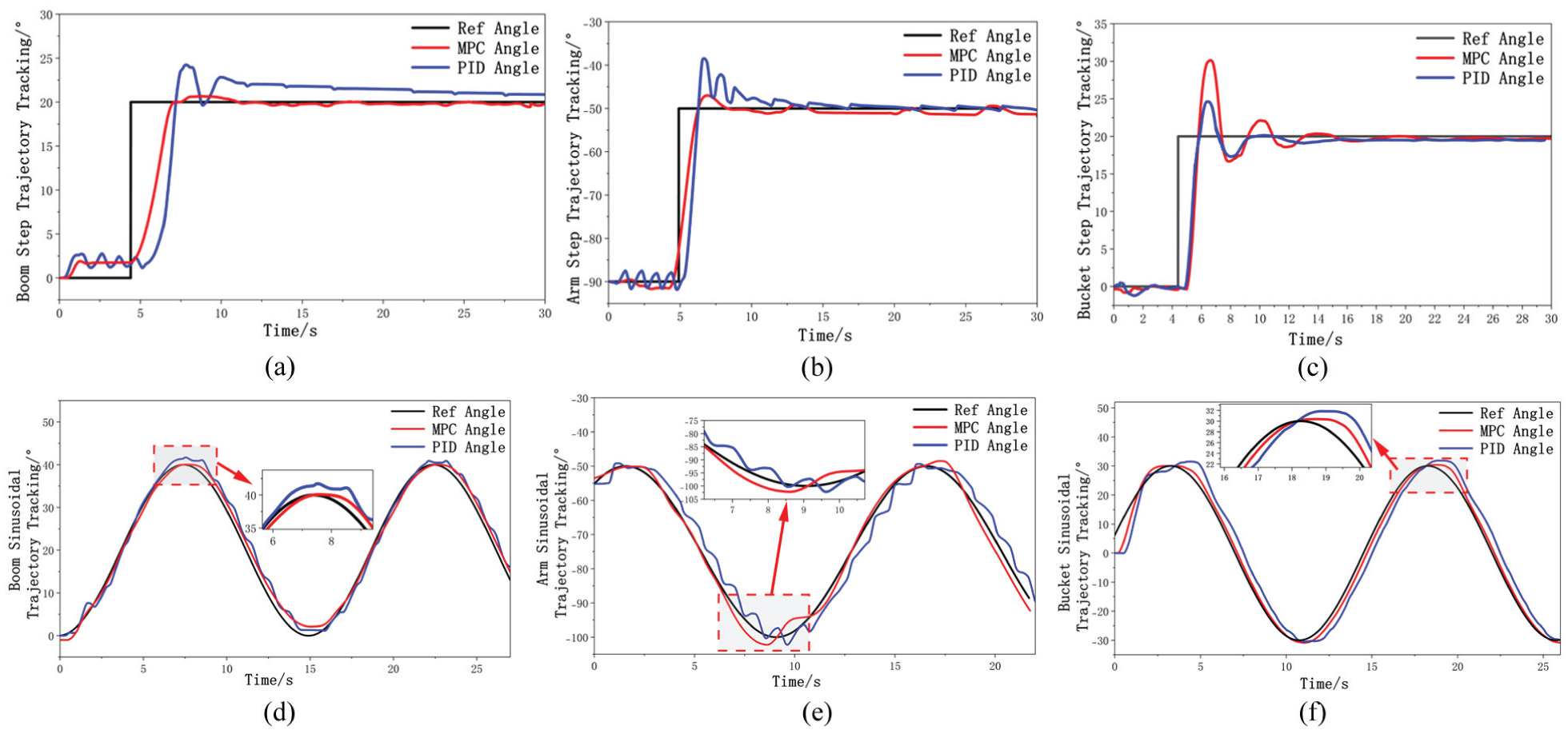
Simulation results of standard signal tracking responses. (a)–(c) Step responses of boom, arm and bucket; (d)–(f) Sinusoidal tracking responses of boom, arm and bucket.
These results demonstrate that the proposed NMPC method provides significantly improved transient response, reduced overshoot, enhanced phase tracking capability, and smoother motion compared with the conventional PID controller, thereby validating its effectiveness for high-precision trajectory tracking of hydraulic excavator manipulators.
Real excavation trajectory tracking
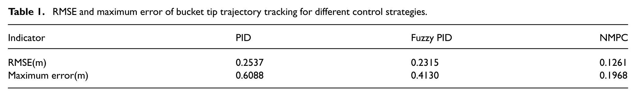
Simulations with realistic excavation trajectories were conducted to evaluate the controller’s performance under practical multi-joint coordinated operation. Without delay compensation, the maximum bucket tip tracking error reached 0.76 m (Figure 6(a)). Subsequently, simulation experiments were conducted using the new control strategy, and a comparative analysis was performed among three control methods: conventional PID, fuzzy PID, and the proposed delay-compensated NMPC (with a 0.5-second delay). The results demonstrate that the proposed delay-compensated NMPC trajectory tracking algorithm achieves significantly enhanced tracking accuracy and stability, with the maximum tracking deviation of the bucket tip relative to the planned trajectory reduced to 0.19 m. Quantitative results in Table 1 further demonstrate that the delay-compensated NMPC reduces the RMSE and maximum error by 50.27% and 67.66% compared with PID, and by 45.50% and 52.34% compared with fuzzy PID, validating its significant superiority in practical excavation trajectory tracking.
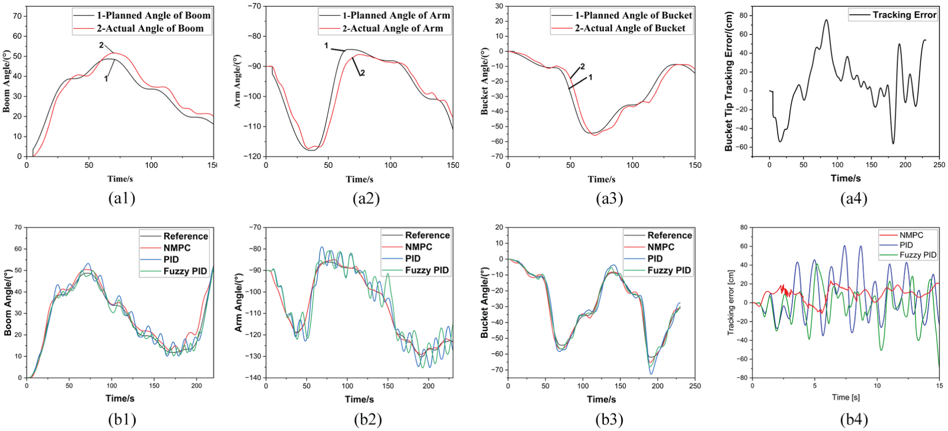
Trajectory tracking simulation results. (a) Without delay compensation, (b) with delay compensation. (a1) Boom. (a2) Arm. (a3) Bucket. (a4) Tracking error. (b1) Boom. (b2) Arm. (b3) Bucket. (b4) Tracking error.
RMSE and maximum error of bucket tip trajectory tracking for different control strategies.
Field experiments
Experimental site and hardware deployment
The field experiments for this study were conducted in a complex operational environment, with significant terrain variations including areas with accumulated crushed stone and multiple mining pits of varying sizes. This setup effectively simulates a wide range of real-world working conditions that excavators might encounter in engineering operations. Figure 7(a) shows the specific experimental site, including the actual excavator, working area, sensor installation positions on the excavator, and the upper computer control interface.
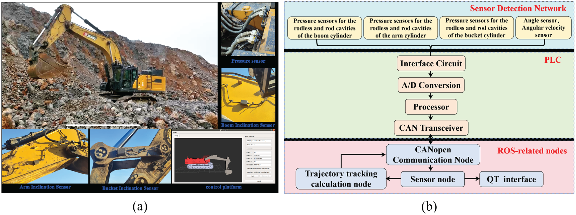
Experimental site and hardware design flowchart. (a) Field experimental site. (b) Hardware architecture of the trajectory tracking system.
The design scheme of the heavy-duty electro-hydraulic manipulator trajectory tracking system is illustrated in Figure 7(b). The system primarily consists of a multi-physical-signal sensing network, a lower computer programmable logic controller (PLC), and an upper computer. The sensing network acquires various physical quantities, including hydraulic pressure, joint angles, angular velocities, and angular accelerations, through different types of sensors. The lower computer, implemented using the IMC T3240 PLC from WIKA, handles the conversion and normalization of the sensor data, which are then packaged and transmitted to the upper computer. The upper computer, a Dongtian IPC-610L industrial computer running Ubuntu 18.04, deploys the NMPC algorithm, which was initially developed in the simulation phase and subsequently converted into C++ code. The NMPC controller operates as an robot operating system (ROS) node, and constrained optimization problems are solved using the open-source nonlinear programming solver IPOPT. Detailed specifications of sensors and the DAQ system are provided in Supplemental Appendix A.
Real-time experimental workflow
A reference joint angle sequence defining the excavator’s desired motion trajectory was pre-generated via the trajectory planning algorithm prior to field tests. Onboard sensor signals were acquired by PLC, preprocessed, and transmitted to the industrial computer via the CANopen protocol. Communication between ROS and CANopen devices was established using the ros_canopen package, with a data publication frequency of 100 Hz for angle sensors and 10 Hz for hydraulic pressure sensors. The control frequency was reduced from the simulated 100 to 50 Hz in field tests to avoid system latency caused by onboard hardware computational limitations, ensuring stable real-time operation. The optimized control signals were published as ROS topics, converted back to CAN signals, and transmitted to the PLC to drive the actuators. All experimental data were synchronously logged at 50 Hz for post-processing and analysis in MATLAB.
Experimental results
To comprehensively verify the trajectory tracking performance of the NMPC algorithm, the experiments were organized into three stages: standard signal tracking experiments, single-joint tuning tests, and multi-joint coordinated motion experiments.
Standard signal tracking experiments
Step and sinusoidal benchmark signals were applied independently to each joint to evaluate the controller’s fundamental dynamic performance (Figure 8(a) and (b)). In step response tests, all joints reached the target position with overshoot below 10%, no sustained oscillations, and maximum steady-state errors of 0.54° (boom), 3.4° (arm), and 1.5° (bucket). The boom joint exhibited a slightly slower response due to its larger inertia and hydraulic load, whereas the arm and bucket joints achieved faster convergence. For the sinusoidal tracking tests, smooth periodic reference trajectories were applied to evaluate phase tracking capability and motion smoothness. The corresponding results for the boom, arm, and bucket joints are shown in Figure 8(b). The NMPC controller achieved stable periodic tracking with small phase lag and minimal amplitude attenuation. However, due to the dead-zone characteristics of the hydraulic system, the boom joint showed noticeable tracking deviation near the turning points of the sinusoidal trajectory, where rapid direction changes occur. Despite these limitations, the tracking trajectories remained continuous without significant chattering.
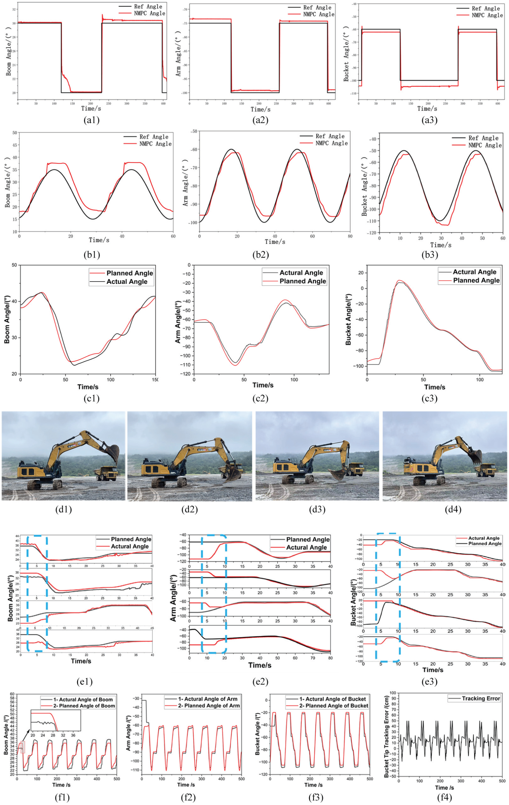
Experimental control and trajectory tracking results. (a) Step responses, (b) sinusoidal tracking responses, (c) single-joint trajectory tracking. (d) Actual excavator poses at four key trajectory points. (e) Trajectory tracking from random initial positions. (f) Multi-joint coordinated trajectory tracking. (a1) Boom. (a2) Arm. (a3) Bucket. (b1) Boom. (b2) Arm. (b3) Bucket. (c1) Boom. (c2) Arm. (c3) Bucket. (d1) Initial position. (d2) Digging-in. (d3) Digging-out. (d4) Dumping. (e1) Boom. (e2) Arm. (e3) Bucket. (f1) Boom. (f2) Arm. (f3) Bucket. (f4) Tracking error.
These experimental results confirm that the proposed NMPC algorithm provides reliable transient response, acceptable steady-state accuracy, and smooth motion control for individual joints under both abrupt and continuous reference inputs. Therefore, the controller possesses the necessary dynamic characteristics for subsequent tuning and coordinated motion experiments.
Single-joint tuning experiments
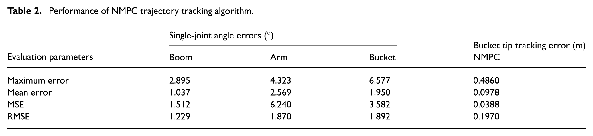
Independent motion tuning was conducted for the boom, arm and bucket joints (5 repeated tests per joint, 15 total), with the core objective of optimizing the relative weighting between the angle-tracking and angular-velocity-tracking terms in the NMPC cost function. A sensitivity analysis was performed on the weighting coefficients to evaluate the controller’s robustness to parameter selection. Results show that excessively large angle-tracking weights lead to aggressive control actions, increased overshoot and potential oscillations, while overly large velocity-tracking weights produce smoother responses but slower convergence and larger steady-state errors, indicating that controller performance is highly sensitive to the balance between tracking accuracy and motion smoothness. The final optimized weighting parameters were determined via repeated testing: boom (Qθ = 30, Qω = 5), arm (Qθ = 25, Qω = 4), and bucket (Qθ = 20, Qω = 3), which achieved the optimal balance between tracking speed and motion stability. Under these parameters, the maximum single-joint tracking errors were limited to 2°–7°, with RMSE below 2° (Table 2, Figure 8(c)). These parameters served as the baseline for subsequent coordinated motion experiments.
Performance of NMPC trajectory tracking algorithm.
Multi-joint coordinated motion experiments
Twelve independent coordinated motion trials were conducted with random initial postures to cover common excavation configurations. The first 11 trials each lasted at least 150 seconds, covering two or more complete trajectory cycles, while the final trial lasted 520 seconds for long-term stability verification (covering seven full cycles). A cyclic excavation trajectory was planned based on the on-site material pile layout, covering four key operating points (initial position (0, -10,000, 2000), digging-in (0, -8723, -449), digging-out (0, -5196, 1200), dumping (5196, 0, 1200); Figure 8(d)). In these trials, trajectory tracking was activated at approximately 5 seconds. The boom, arm, and bucket angles converged to the reference trajectory within roughly 4 seconds after activation, suggesting that the NMPC controller exhibits relatively stable tracking behavior under the tested conditions (Figure 8(e)).
The overall tracking performance during full trajectory cycles is summarized in Figure 8(f), which compares the planned and measured joint angles, as well as the resulting bucket-tip tracking error computed through forward kinematics. Across all experiments, the maximum tracking error of the bucket tip was 48.6 cm. The quantitative evaluation of the NMPC tracking accuracy is presented in Table 2 (column for bucket tip tracking error).
These results also demonstrate the practical closed-loop stability of the proposed NMPC controller. The finite prediction horizon, positive definite weighting matrices, and input constraints ensure bounded optimization solutions at each sampling step, preventing excessive control actions. Moreover, the receding-horizon implementation continuously updates the control input based on real-time feedback, compensating for model mismatch and disturbances. Extensive simulation and field experiments show that the system maintains bounded tracking errors and smooth actuator responses without divergence or sustained oscillations.
Noticeable tracking deviations occurred at joint angle transition points, with two primary error sources identified:
Hydraulic model discrepancies between the identified model and the actual system, caused by model simplifications and limited experimental data scope.
Computational frequency constraints, where the reduced 50 Hz control update rate (from the designed 100 Hz, limited by onboard hardware) led to larger errors during rapid joint transitions.
Conclusion
In this study, a comprehensive NMPC framework for trajectory tracking of an unmanned ultra-large hydraulic excavator was developed and experimentally validated. First, the kinematic and dynamic models of the excavator were derived, and the nonlinear hydraulic system was identified as a Hammerstein–Wiener structure through equation simplification and parameter fitting. Based on this model, a displacement–velocity control framework for the hydraulic cylinders was established and incorporated into the NMPC formulation. A high-fidelity simulation platform was constructed in the MATLAB/Simulink environment to evaluate the proposed control strategy. To address the significant delay observed in the hydraulic system during field tests, a 0.5-second predictive advance compensation strategy was further introduced to improve tracking responsiveness.
The investigated system is a 69-ton ultra-large mining hydraulic excavator, characterized by high inertia, long hydraulic transmission lines, and strongly varying external loads. Both simulation and field experiments demonstrate that the proposed NMPC-based control strategy achieves stable and reliable trajectory tracking under diverse initial configurations. Simulation results show that the bucket-tip tracking error can be limited within 0.2 m, while the maximum error observed in field experiments is 0.486 m, which satisfies the operational requirements of typical open-pit excavation tasks. These results confirm the effectiveness of the proposed framework for controlling heavy-duty hydraulic manipulators operating under severe nonlinearities and delays.
Despite these promising results, the study also reveals several factors that limit tracking accuracy, including hydraulic model mismatch and constraints on onboard computational resources. Future research will therefore focus on three main directions:
Optimizing the hydraulic system model to mitigate dead-zone effects and improve modeling accuracy via higher-order models or multi-sensor data fusion.
Exploring lightweight optimization algorithms or hardware acceleration to reduce the embedded computational load, and introducing dynamic weight adjustment based on real-time reference trajectory curvature to enhance control precision at transition points.
Adaptive or learning-based enhancements will be explored to enable real-time parameter adjustment and improved robustness under changing operating conditions.
These advancements are expected to further enhance the applicability of NMPC to large-scale autonomous excavation systems and other heavy hydraulic machinery.
Supplemental Material
sj-xlsx-1-tim-10.1177_01423312261453632 – Supplemental material for Hammerstein–Wiener model-based nonlinear model predictive control for trajectory tracking of unmanned hydraulic excavators
Supplemental material, sj-xlsx-1-tim-10.1177_01423312261453632 for Hammerstein–Wiener model-based nonlinear model predictive control for trajectory tracking of unmanned hydraulic excavators by Jiwen Liu, Yaxin Wu, Huan Yang, Di Hu, Haiying Wen, Ran Zhang, Jintao Chen and Bo Yang in Transactions of the Institute of Measurement and Control
Footnotes
Ethical Considerations
This article does not contain any studies with human or animal participants.
Consent to Participate
There are no human participants in this article and informed consent is not required.
Consent for Publication
Not applicable. No individual human data or identifiable images are included in this manuscript.
Funding
The authors disclosed receipt of the following financial support for the research, authorship, and/or publication of this article: This research was supported by Jiangsu XuGong National Key Laboratory Technology Co., Ltd., and The Jiangsu Province Key R&D Plan (Industrial Foresight and Key Core Technologies) (BE2023008-3).
Declaration of conflicting interests
The authors declared no potential conflicts of interest with respect to the research, authorship, and/or publication of this article.
Data Availability Statement
The data that support the findings of this study are available from the corresponding author upon reasonable request.
Supplemental material
Supplemental material for this article is available online.
References
Supplementary Material
Please find the following supplemental material available below.
For Open Access articles published under a Creative Commons License, all supplemental material carries the same license as the article it is associated with.
For non-Open Access articles published, all supplemental material carries a non-exclusive license, and permission requests for re-use of supplemental material or any part of supplemental material shall be sent directly to the copyright owner as specified in the copyright notice associated with the article.