






Abstract
To address significant current ripple and current gradient stagnation in conventional model-free predictive current control for permanent magnet synchronous motors, this article proposes an enhanced three-vector control strategy with adaptive current gradient updating. The method overcomes the limitation of fixed vector amplitude and direction per control cycle inherent in conventional model-free predictive current control using a combination of two adjacent active vectors and a zero vector within one period, thereby expanding the achievable output voltage range. The voltage equation is concurrently reformulated based on the current gradient principle. Next, the current gradient error corresponding to the vector application times is determined. These errors are then used by a moving least squares algorithm to adaptively update the current gradients associated with the applied vectors. Critically, this process facilitates the update of gradients for all potential voltage vectors within a single control cycle, effectively eliminating gradient update stagnation. Furthermore, the voltage sector division is optimized, and the optimal voltage vector combination is screened through cost function ranking, achieving accurate vector selection with minimal computation. Experimental results validate the proposed strategy, demonstrating its ability to reliably update the online current prediction model, reduce prediction errors and current ripple significantly, and achieve enhanced transient response and steady-state performance.
Keywords
Introduction
Permanent magnet synchronous motor (PMSM) is widely utilized in fields such as aerospace, medical robotic joint drives, and semiconductor manufacturing, owing to its simple structure, high efficiency, and high power density (Yan et al., 2023; Zhang et al., 2019a). However, PMSM is subject to uncertainties such as time-varying nonlinear parameters, external disturbances, and measurement errors during operation, which render conventional linear control methods insufficient for achieving fast and accurate torque control in servo applications (Chen et al., 2022; Niu et al., 2015).
With the rapid advancement of digital processors, model predictive current control (MPCC) has gained popularity in PMSM applications due to its simple control structure, fast dynamic response, and capability to handle nonlinear constraints (Zhang et al., 2018, 2019b, 2022). However, the reliance of MPCC on accurate system models implies that its control performance is highly sensitive to parameter uncertainties (Young et al., 2016). In practical applications, PMSM parameters may be unknown or subject to variation due to factors such as temperature rise and magnetic saturation, leading to model mismatch, prediction errors, and degraded control performance.
To enhance the robustness of MPCC against parameter variations, two main strategies have been explored: parameter identification (Brosch et al., 2021; Wang et al., 2022, 2024; Wu et al., 2020) and observer-based compensation (Mousavi et al., 2021; Zhang et al., 2019a, 2023). Parameter identification methods estimate motor parameters based on system inputs and outputs to mitigate the impact of model mismatch. However, online identification may suffer from rank deficiency and convergence issues. For example, Wu et al. (2020) employ high-frequency voltage injection to incrementally estimate parameters, introducing additional harmonics and energy losses. In Zhang et al. (2019a), an extended sliding mode observer estimates inductance variations but neglects the effects of resistance variation. Mousavi et al. (2021) propose an extended observer to estimate total disturbances and apply feedforward compensation, which improves adaptability in multi-vector MPC. While these observational methods and parameter identification techniques enhance adaptability, they increase implementation complexity and may overlook the impact of certain parameters on the model.
Model-free predictive current control (MFPCC) has emerged as a promising approach to enhance parameter robustness. These methods primarily include ultra-local model-based techniques and approaches based on current gradient look-up table (LUT) updates. According to Zhang and Wang (2023) and Zhang et al. (2021), the ultra-local model is used to replace the detailed motor dynamics model, and lumped disturbances are estimated for compensation. To reduce parameter dependence while avoiding the complexity introduced by observers, several researchers have proposed fully model-free predictive control strategies that record current differentials during inverter switching transitions and use these records to update the LUT based on current gradients (Carlet et al., 2019; Lin et al., 2014; Ma et al., 2021; Yu et al., 2021). However, these methods suffer from gradient update stagnation for unused voltage vectors, which can degrade control performance (Yu et al., 2021). Carlet et al. (2019) attempt to update residual vector gradients using the gradients of the most recently applied vectors, while Ma et al. (2021) estimate not updated gradients via linear interpolation based on gradient differences across control cycles. However, stagnation still occurs when voltage vectors between cycles remain similar.
Moreover, most LUT-based MFPCC schemes apply a single voltage vector per control cycle, limiting the output voltage range and leading to increased current ripple. Under conditions of slight parameter mismatch, the control performance of single-vector MFPCC is inferior to that of multi-vector MPC. Expanding the vector output range through multi-vector schemes has been shown to enhance steady-state performance (Jin et al., 2022; Niu et al., 2021; Xu et al., 2022; Zhang et al., 2018). However, the complex current dynamics under multi-vector control, as well as the need to determine the precise sequence and duration of each vector, complicate current gradient estimation has constrained the development of multi-vector MFPCC. In Ma et al. (2023), a zero vector is combined with an active vector to extend the output range, but it requires additional current sampling at the half-cycle point. In Sun et al. (2023), current gradients for all vectors are estimated using a sliding mode observer within an ultra-local model framework; however, this approach increases system complexity and may yield suboptimal duty cycles.
This article proposes a model-free three-vector predictive current control strategy for PMSM, in which an adaptive moving-least-squares (MLS) method is employed to update current-gradient LUTs for enhanced multi-vector MFPCC performance. First, the dq-axis voltage equations are reformulated into a current gradient model that distinguishes between the natural and forced components of the response. The current error propagation characteristics of the three-vector prediction scheme are analyzed, and the current error is distributed based on vector type and duration. The MLS method is then employed to construct an adaptive correction model based on historical current errors, enabling symmetric updates to all gradient entries in the LUT and improving prediction accuracy. Finally, an optimal vector selection algorithm is introduced to reduce the search space and computational burden. Compared with the multi-vector FCS-MPCC methods, the proposed MLS-MFPCC explicitly captures segmented current dynamics by fitting local linear models, thereby eliminating the dependence on a fully parameterized motor model. In contrast to observational methods and parameter identification techniques, MLS-MFPCC avoids reliance on recursive observer structures and model identification, reducing algorithmic complexity and sensitivity to excitation and initialization while providing a robust, data-driven local approximation. Furthermore, unlike conventional MFPCC, the MLS-MFPCC updates the current gradients of all voltage vectors within a single control cycle, effectively preventing gradient update stagnation, and outputs three voltage vectors per cycle to extend the available voltage range. Consequently, MLS preserves the low implementation cost and strong robustness of LUT-based MFPCC while further improving steady-state performance. Experimental results verify that the proposed strategy effectively updates the current LUT, reduces prediction error, and achieves superior dynamic and steady-state performance.
Mathematical model of the PMSM system
According to the forward Euler discretization method, the discrete-time voltage equation of a surface-mounted PMSM in the synchronous rotating reference frame is given by:

where
As shown in equation (1), the discrete motor model is used to analytically compute the control voltage, and the accuracy of the model-based predictive current control (MBPCC) framework based on PMSM parameters is highly dependent on the accuracy of those parameters. However, the initial parameters of the PMSM are often difficult to obtain precisely, and during operation, the actual motor parameters may deviate from their nominal values. Such parameter mismatches can result in significant discrepancies between predicted and actual current values, thereby degrading control accuracy and potentially inducing system oscillations.
To mitigate the adverse effects of parameter uncertainties, MFPCC, which relies solely on current and voltage measurements without requiring explicit knowledge of system parameters, has been proposed. In this method, the current estimation can be expressed as:

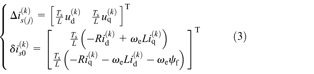
where
To compensate for the one-step delay inherent in the system, the predicted current

MFPCC evaluates all candidate voltage vectors using a cost function and selects the optimal output vector accordingly. The formulation of the cost function depends on the specific control objective. For dq-axis current control, the cost function can be expressed as:

where
Proposed MLS-MFPCC method
To address the challenges of large current ripple and stagnation in current gradient updates observed in single-vector MFPCC, this article proposes a method that applies three voltage vectors within a single control cycle. The historical prediction error is employed to perform real-time correction of the current gradient lookup table based on the MLS approach. In addition, the spatial symmetry of the voltage vectors is leveraged to update the gradients of all voltage vectors simultaneously within each cycle.
Three-vector error distribution
The current trajectory and prediction error are illustrated in Figure 1;

where the subscript i denotes the sequence index of the non-zero voltage vectors within a control cycle.
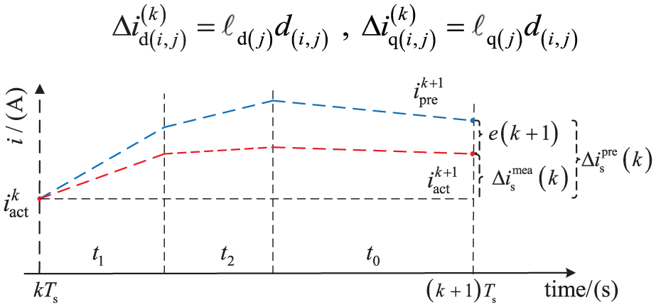
Current trace and prediction error.
In Figure 1, the dashed line illustrates the current trajectory predicted based on the LUT, while the solid line corresponds to the actual measured current trajectory. The variable

where

where
In conventional MFPCC, the current-gradient information available within each control period is limited, and the gradients associated with discrete voltage vectors differ from one another, leading to multiple variables to be estimated and potential gradient-update stagnation. To establish the mapping between seven discrete voltage vectors and their corresponding current gradients within a single control cycle, equation (1) is reconstructed into equation (2) to enhance the symmetry of the current-gradient representation. The current increment over one cycle can be approximated as a weighted linear combination of the forced current responses of two adjacent active voltage vectors and the natural response of the zero vector, yielding a linear regression formulation for gradient estimation. Based on this local linear relationship, an online MLS algorithm with a sliding window is adopted. The MLS framework effectively improves robustness to measurement noise and switching ripple by utilizing multiple recent samples, while its equivalence to a normalized least-mean-square-type update law ensures analytical tractability, guaranteed convergence, and low computational complexity suitable for real-time implementation in high-bandwidth current control loops. The following are the specific steps for implementing the algorithm.
Based on the voltage vector applied at the (k−1)th instant, the LUT entries with the same index in the historical output vector and their corresponding errors totaling N samples are utilized to construct the MLS function as follows:

where

To ensure system stability, after obtaining

The bound
During operation, online adaptive adjustment based on the error magnitude is necessary to enable rapid correction in the large-error stage and smooth tracking during the small error stage.


In order to balance the rapidity and stability of tracking, β is selected such that the equivalent memory time
Three distinct voltage vectors are applied within each control cycle; the regressor matrix formed by their dq-axis components is inherently full rank, thereby satisfying the persistence of excitation condition and ensuring parameter identifiability. Therefore, in each iteration, the LUT can be modified based on historical samples using least-squares fitting, while algorithm stability is ensured through learning rates, forgetting factors, and amplitude constraints.
Improved three-vector search method
This article adopts a three-vector control strategy, in which two adjacent non-zero basic voltage vectors and one zero voltage vector are applied within each control period. This approach reduces the error between the output voltage vector and the reference vector, thereby minimizing current ripple and enhancing control performance.
However, using three vectors increases the computational burden. In contrast, the single-vector method applies one voltage vector throughout the entire control period, without requiring time optimization. Thus, the cost function values for the seven candidate vectors can be evaluated sequentially using (5) to determine the optimal vector, with relatively low computational complexity.
In the three-vector method, both the selection of vector combinations and the calculation of vector durations must be performed simultaneously. If an exhaustive search is used, the computational load becomes excessive. Therefore, this article proposes an optimized search strategy to reduce the computational effort required for cost function evaluation.
Three non-zero basic voltage vectors that are 120° apart from each other are selected. Taking
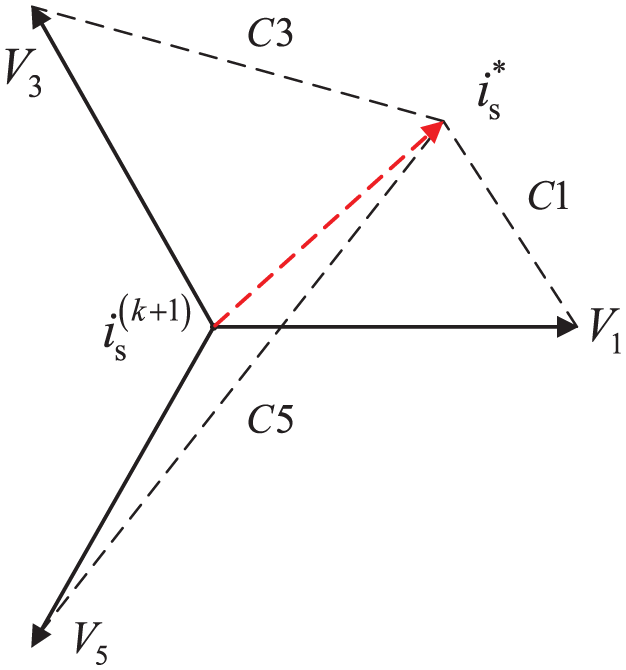
Reconstruction of the voltage phase plane.
Considering that the current after one-step delay compensation is

By substituting (14) into (15), the cost function values corresponding to these three voltage vectors are calculated and ranked in ascending order.

As illustrated in Figure 2, the cost function value is quantified as the Euclidean distance between each candidate voltage vector and the reference current vector. In this example,
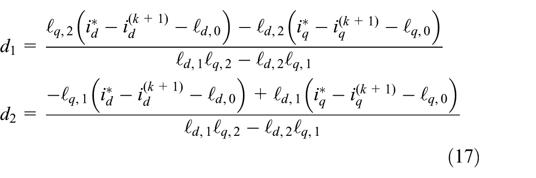
When combined with the zero vector, the duration of each of the three vectors can be derived from the following equation:

In this article, adjacent non-zero fundamental voltage vectors are selected as the output vectors within each control period; thus,
Under sudden load disturbances or significant variations in speed reference, the expected voltage command may exceed the linear modulation range of the inverter, leading to overmodulation. In such cases, the duty ratio must be adjusted accordingly to ensure that the output voltage remains within the allowable modulation boundaries. The adjusted duty ratio expression is as follows:

Symmetric updates
In this article, equation (6) is employed to decompose the current increment into natural and forced components of the current response. According to equation (3), the LUT of non-zero voltage vectors contains only the voltage magnitudes, which can be represented as

The non-zero fundamental voltage vectors have equal magnitudes and are spatially symmetric with respect to each other. As a result, the corresponding entries in the LUT for collinear voltage vectors are additive inverses. Moreover, the method proposed in this article applies two adjacent non-zero fundamental voltage vectors within each control period. By synthesizing these vectors, the LUT for the remaining two fundamental voltage vectors can be derived accordingly. The symmetry relationship of the current gradient is illustrated in Figure 3. Taking the reference current in the first sector of the (k−1)th period as an example, three voltage vectors are applied during this period:
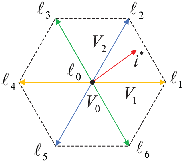
Symmetrical renewal of the current gradient.
At the kth instant, after updating

According to the computation sequence in equation (20), the system completes the update of all seven vectors within a single control period. Similarly, when the output vector lies in other sectors, the same geometric relationship can be employed to update the entire LUT within one control period, thereby effectively preventing stagnation in the current gradient updates.
Block diagram of MLS-MFPCC
At the kth sampling instant, measure the current and speed, and compute the prediction error by comparing the actual measured current with its predicted value. Subsequently, calculate the prediction error for each voltage vector based on the vector combination and duty ratio applied during the (k−1)th cycle.
Integrate the historical error data to construct updated MLS data, then update the LUT corresponding to the voltage vector combination of the (k−1)th cycle according to (13). Finally, employ vector symmetry to update the LUT entries of the remaining four vectors.
Calculate
Based on the above analysis, the block diagram of the PMSM three-vector control system based on current gradient adaptive updating is shown in Figure 4.
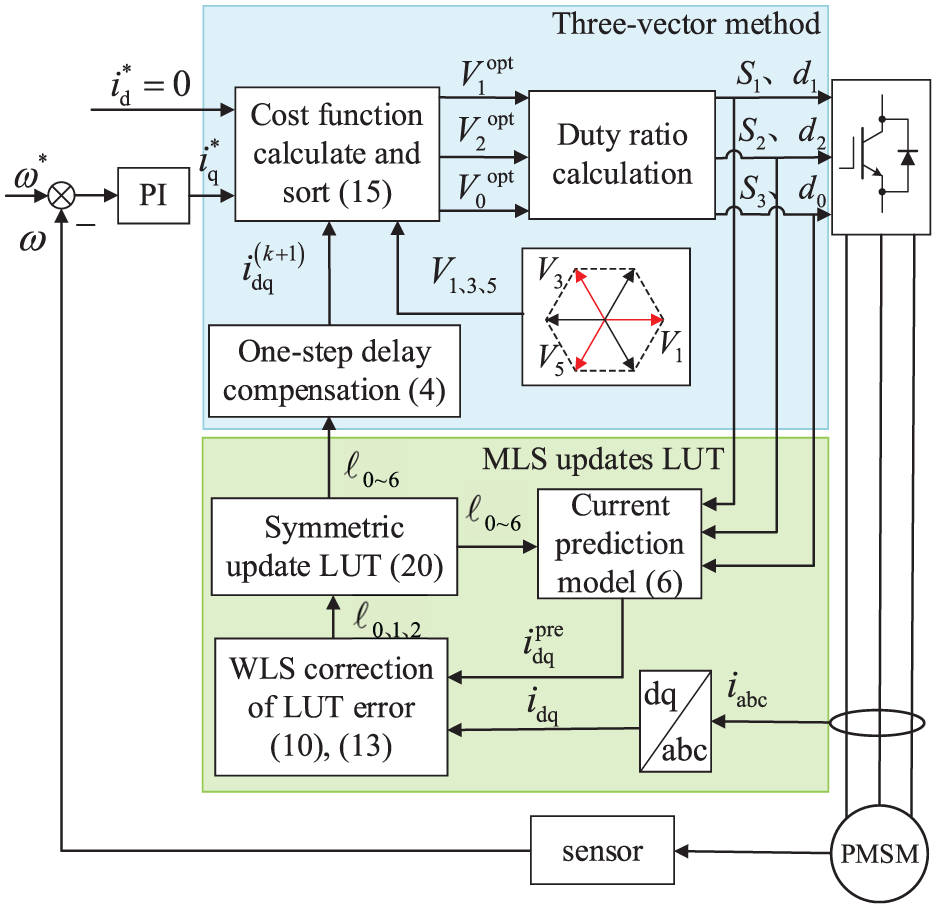
Block diagram of MLS-MFPCC controller based on adaptive current gradient update.
System experimental results and analysis
The effectiveness of the proposed method was validated through comparative experiments conducted on the test platform depicted in Figure 5. The experimental setup comprised a PMSM, a host computer, a Links-BOX real-time simulator, a servo drive, sensors, magnetic powder brakes, and other components.
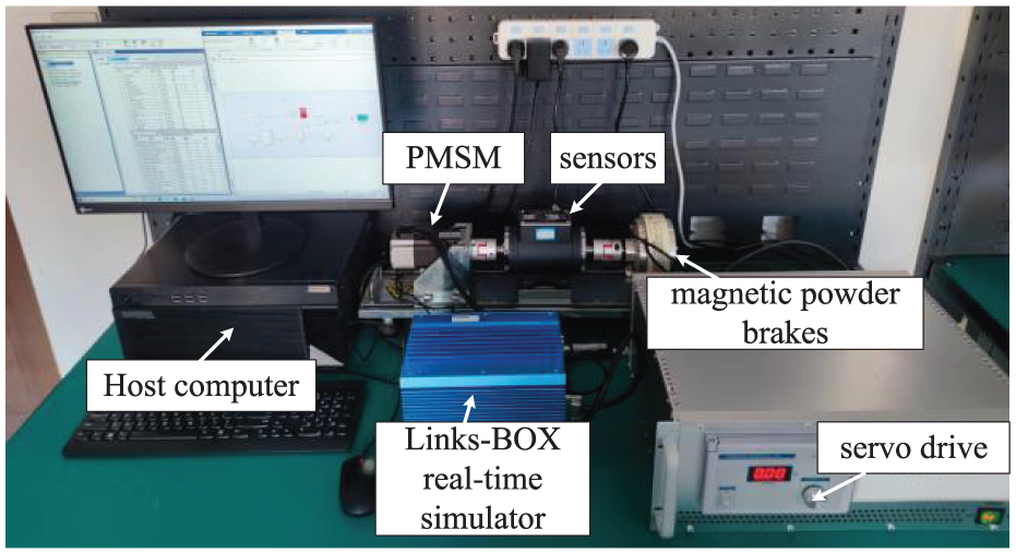
Experimental platform.
The Links-BOX real-time simulator is the core of the Links-RT system, consisting of a CPU, memory, hard drive, and functional expansion boards. The CPU uses an Intel Core i7 processor running the VxWorks real-time operating system. Among the expansion boards, the bus board is used for Ethernet communication with the host computer, while the sensor board, analog board, and digital board are used for acquiring encoder signals, sensor signals, and I/O signals. The sensors use the IN338-type networked intelligent digital torque and speed sensors, with an accuracy grade of 0.2.
The servo drive communicates with the Links-BOX real-time simulator via the PCI bus. The servo drive includes a motor drive board based on the DSP TMS320F28335 and a power supply main circuit board. The primary function of the motor drive board card is to output motor drive signals, providing six complementary PWM signals with dead-time settings. In addition, it includes functionality to drive a magnetic powder brake to regulate load torque and signal acquisition capabilities (such as measuring two-phase motor current and DC bus voltage). The power supply main circuit consists of a rectifier bridge and a three-phase inverter. Its primary function is to rectify 220 V AC power into DC voltage and drive the PMSM via the three-phase inverter. The main control computer serves as the host computer. It first runs MATLAB/Simulink software to model and design the motor control algorithm, then generates target code using the Simulink interface software RT-Lib and RT-Coder software, and finally transmits the code via Ethernet to the Links-BOX real-time simulator. The VxWorks target machine performs real-time simulation, saves experimental data in the workspace, and can export it to MATLAB for plotting.
The PMSM adopts the
Steady-state performance
In MBPCC, as shown in equation (1), the discrete motor model is used to analytically compute the control voltage, and the resulting continuous voltage is implemented using a three-vector PWM scheme.
Figure 6(i) compares the steady-state experimental results of MBPCC, conventional MFPCC, and the proposed MLS-MFPCC under accurate parameter conditions at a rated speed of 750 r/min, with load torques of 2 and 5 N·m. The total harmonic distortion (THD) of the phase current and the ripple amplitudes of the dq-axis currents are presented. The proposed MLS-MFPCC achieves performance comparable to that of MBPCC: the current THD is nearly identical, the d-axis current ripple is approximately 0.2 A, and the q-axis current ripple is about 0.3 A, with the q-axis current closely tracking its reference. In contrast, under a 5 N·m load, conventional MFPCC exhibits a THD of 6.92% and dq-axis current ripples up to 1.5 A; at 2 N·m, the THD increases to 16.01% with current ripples reaching 1.8 A, leading to severe current pulsations that degrade control performance and increase system losses.
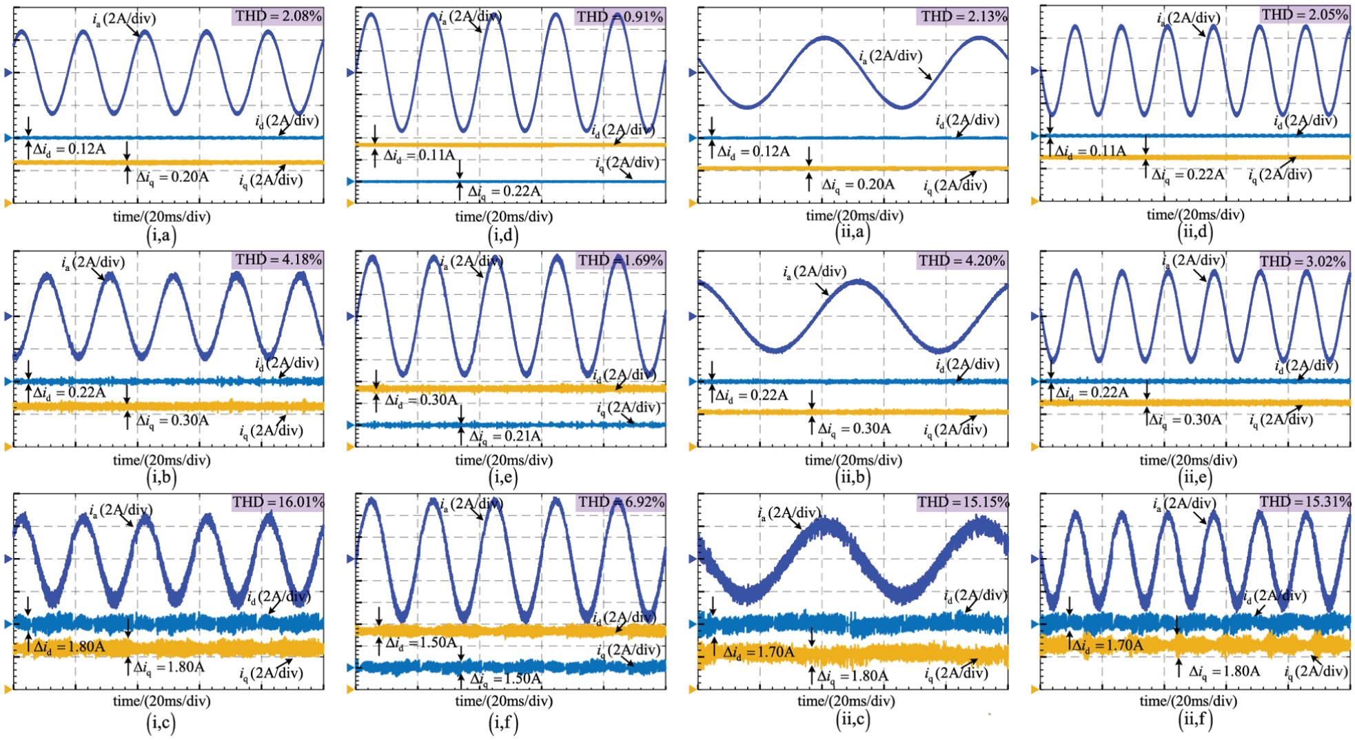
Steady-state performance comparison: (i) At 750 r/min under 2 N·m and 5 N·m loads. (a–c) MBPCC, MLS-MFPCC, MFPCC at 2 N·m; (d–f) MBPCC, MLS-MFPCC, MFPCC at 5 N·m. (ii) At 2 N·m load under 300 and 1000 r/min. (a–c) MBPCC, MLS-MFPCC, MFPCC at 300 r/min; (d–f) MBPCC, MLS-MFPCC, MFPCC at 1000 r/min.
Figure 6(ii) compares the performance of the three methods at a 2 N·m load under operating speeds of 300 and 1000 r/min. Conventional MFPCC shows significant deviations between the dq-axis currents and their reference values, accompanied by notable oscillations. By contrast, the proposed MLS-MFPCC maintains excellent steady-state current tracking performance across the tested speed range.
Figure 7 compares the LUT error profiles of the two model-free methods under four operating conditions. The results show that MLS-MFPCC confines the dq-axis LUT error within 0.30 A, while conventional MFPCC exhibits d-axis errors around 0.50 A and q-axis errors near 1 A, with larger deviations at low and high speeds. This is due to MFPCC’s linear update mechanism, which lacks noise suppression; repeated application of the same voltage vector causes the update denominator to vanish, preventing corrections. In addition, the q-axis current increment strongly depends on motor speed: at high speed, back-EMF reduces the increment, while at low speed, stator inductance effects amplify deviations from linearity, leading to a cumulative negative bias in the q-axis LUT.
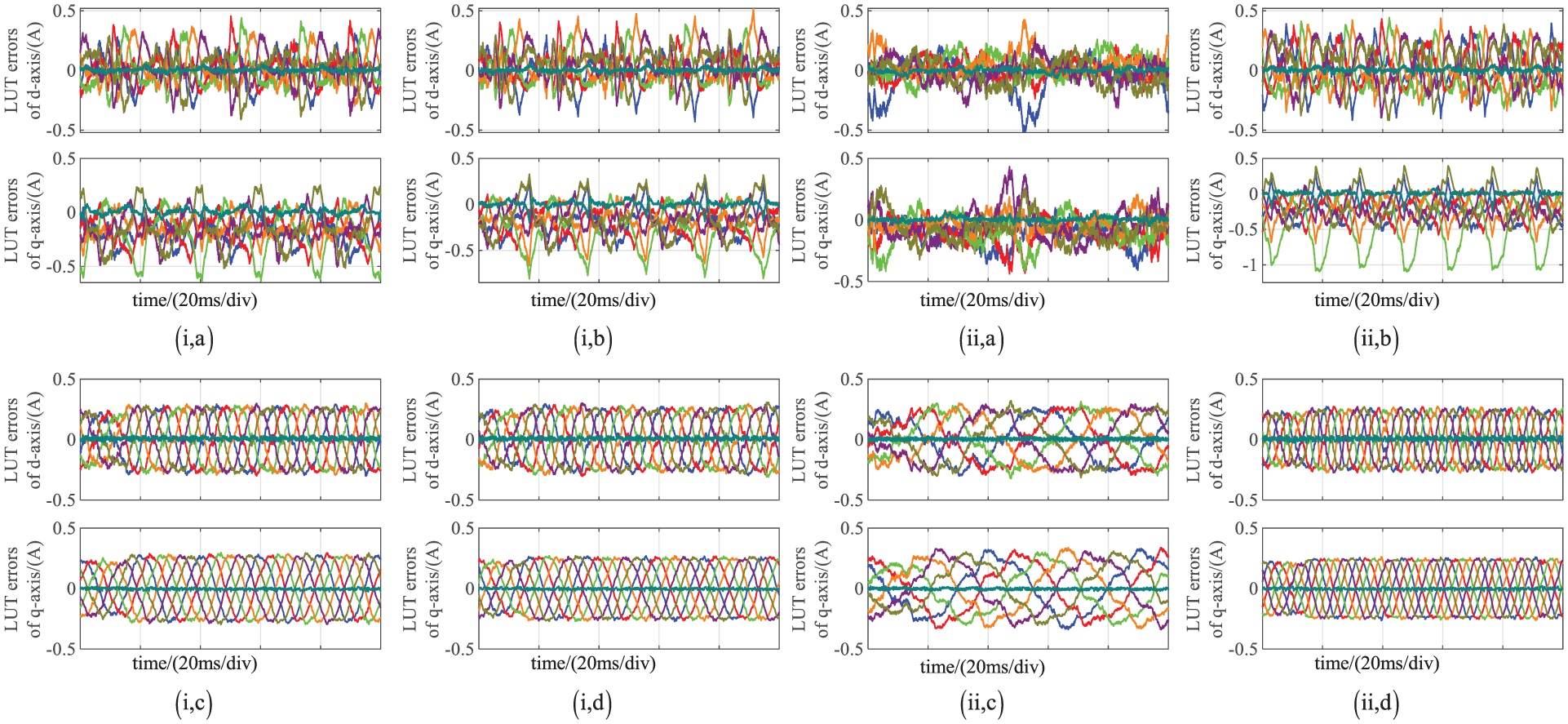
LUT estimation error comparison: (i) At 750 r/min under 2 N·m and 5 N·m loads. (a–b) MFPCC, (c–d) MLS-MFPCC. (ii) At 2 N·m load under 300 and 1000 r/min. (a–b) MFPCC, (c–d) MLS-MFPCC.
In contrast, MLS-MFPCC employs historical error feedback and MLS-based adaptive correction, producing smoother LUT estimates. By decoupling the zero-vector natural response from active vectors, it eliminates DC bias in the zero-vector LUT entries, further improving accuracy. Consequently, MLS-MFPCC achieves steady-state performance comparable to MBPCC without requiring motor parameter knowledge.
Dynamic performance
To evaluate the robustness of MLS-MFPCC under abrupt speed and load changes, two tests were performed: (1) a load step from 2 to 5 N·m at rated speed, and (2) a speed step from 500 to 1000 r/min under 2 N·m load. Figure 8 shows the dynamic current responses, and Figure 9 presents the corresponding LUT errors. MFPCC exhibits larger current oscillations and increased LUT error after the steps due to its linear update requiring multiple cycles to correct inaccuracies, which slows response and increases current ripple. In contrast, MLS-MFPCC maintains LUT errors within 0.32 A, with no noticeable torque disturbances or error spikes, demonstrating rapid convergence, fast dynamic response, and reliable LUT adaptation.
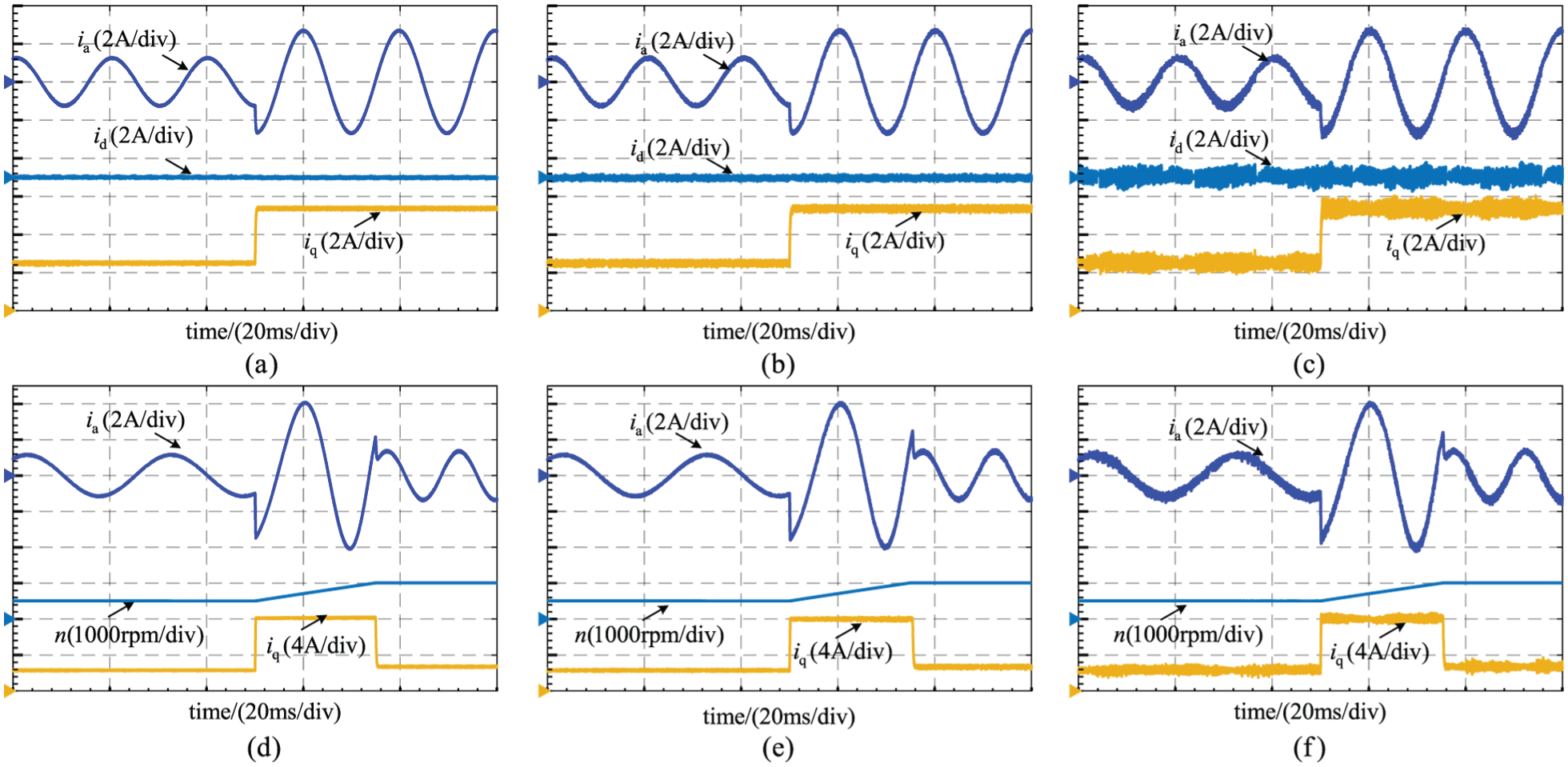
Dynamic performance comparison: (a–c) MBPCC, MLS-MFPCC, and MFPCC under a load torque step at 750 r/min; (d–f) MBPCC, MLS-MFPCC, and MFPCC under a speed step with 2 N·m load.
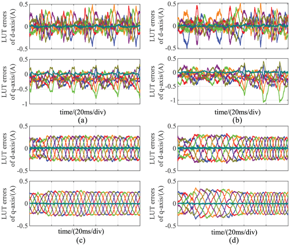
Comparison of the LUT error of both methods under dynamic test. (a) MFPCC method under sudden load changes. (b) MFPCC method under sudden speed changes. (c) MLS-MFPCC method under sudden load changes. (d) MLS-MFPCC method under sudden speed changes.
Under parameter mismatch conditions, the predictive accuracy of the MBPCC model deteriorates, leading to the accumulation of current prediction errors and consequently larger steady-state deviations. In this study, both MBPCC and the proposed MLS-MFPCC adopt a three-vector control structure. A direct comparison with the single-vector MFPCC would therefore be inappropriate, as the observed performance differences could stem from both parameter mismatch effects and inherent disparities in vector synthesis mechanisms. To enable a fair and meaningful comparison, a three-vector MBPCC scheme incorporating a nonlinear extended state observer (NESO-MFPCC) is introduced, allowing the influence of the compensation strategy to be evaluated independently of the vector synthesis framework.
The tests involve sudden torque surges under three sets of mismatched PMSM parameters: Figure 10(a, d, g) dq-axis inductance 50%, stator resistance 10%, flux linkage 200%; Figure 10(b, e, h) dq-axis inductance 200%, stator resistance 1000%, flux linkage 70%; Figure 10(c, f, i) dq-axis inductance 200%, stator resistance 100%, flux linkage 200% of actual values. Figures show A-phase stator current, q-axis, and d-axis currents for each case.
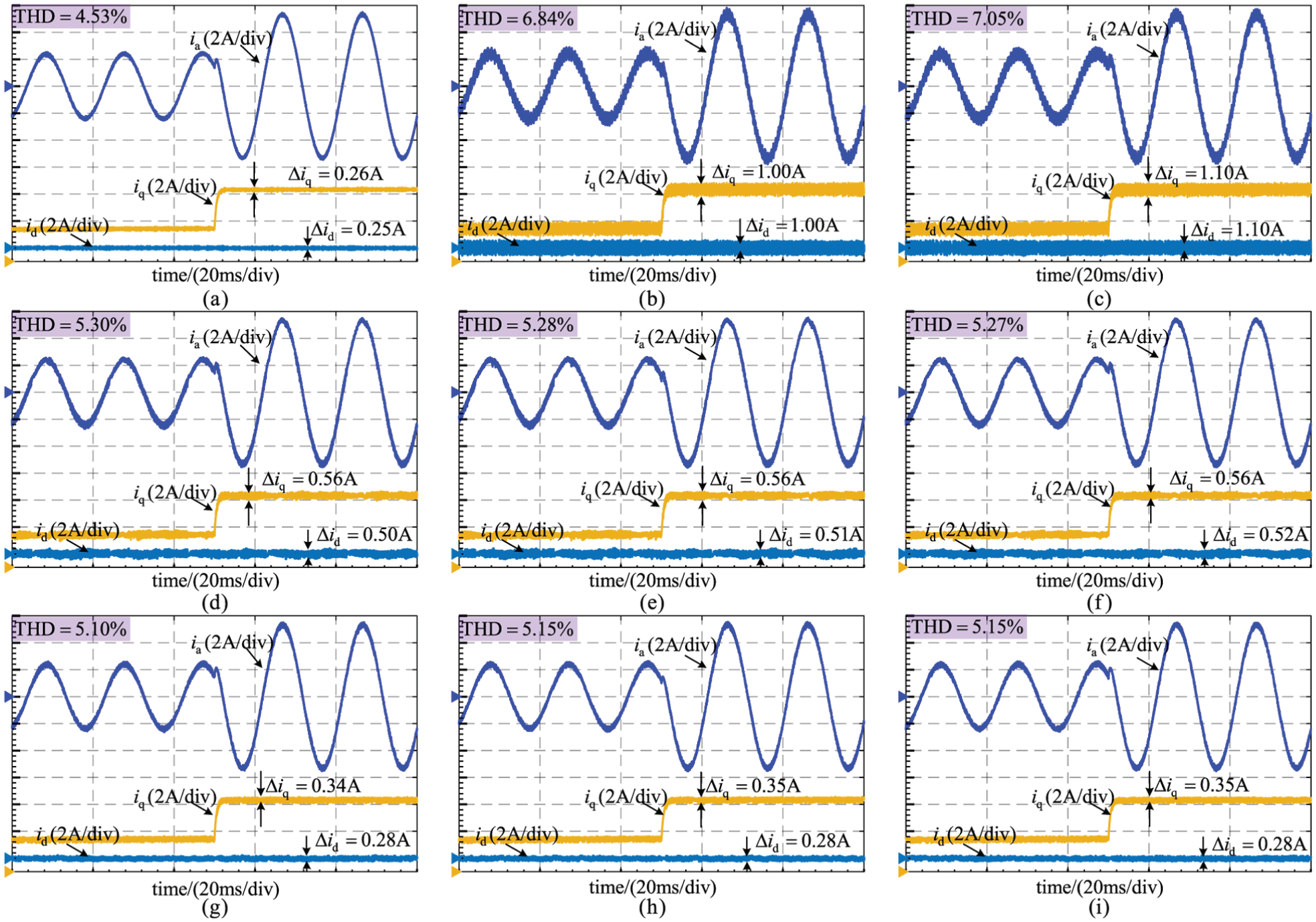
Experimental results during a dynamic process with mismatched parameters. (a) MFPCC
Results indicate that MBPCC exhibits large steady-state errors under parameter mismatch. NESO-MFPCC reduces error via online disturbance compensation, while MLS-MFPCC achieves the best dynamic response, smallest steady-state error, and highest robustness. These findings confirm the effectiveness of the MLS-based current-gradient weighting mechanism for handling model uncertainties in high-precision, robust current control.
A quantitative comparison of computational efficiency shows that single-vector MFPCC requires about 46 μs per cycle, while MLS-MFPCC takes approximately 50 μs due to three-vector synthesis and MLS updates. NESO-MFPCC demands around 65 μs because of recursive estimation and nonlinear observer tuning. Overall, MLS-MFPCC improves steady-state performance with minimal additional computation, remaining feasible for real-time high-bandwidth current control.
Conclusion
In this study, to reduce the impact of uncertainties and improve control performance in PMSM systems, a three-vector MLS-MFPCC method is proposed. First, a decoupled current response model is developed by separating the forced and natural components of the stator current in the dq frame. This formulation eliminates the DC bias effect of the natural response on LUT updates for non-zero voltage vectors, ensuring more accurate current prediction. Next, an online moving least squares algorithm is introduced to adaptively compensate for current gradient estimation errors. A symmetrical voltage vector activation scheme is incorporated to prevent gradient update stagnation and enhance dynamic response. Then, an optimized three-vector synthesis strategy is applied within each control cycle to minimize voltage tracking errors and improve steady-state current performance, while maintaining computational efficiency suitable for real-time implementation.
Experimental results demonstrate that MLS-MFPCC effectively improves LUT accuracy and current tracking under varying speed, load, and parameter conditions. Compared with conventional MFPCC and NESO-MFPCC, the proposed method achieves smaller steady-state errors, faster dynamic response, and stronger robustness against measurement noise, switching ripple, and parameter variations. These results confirm that MLS-MFPCC can satisfy high-precision and robust current control requirements for PMSM applications.
Footnotes

Funding
The authors disclosed receipt of the following financial support for the research, authorship, and/or publication of this article: This work was supported by Liaoning Province Science and Technology Plan Joint Plan under Grant 2024-MSLH-369.
Declaration of conflicting interests
The authors declared no potential conflicts of interest with respect to the research, authorship, and/or publication of this article.
Data availability statement
Data sharing not applicable to this article as no data sets were generated or analyzed during the current study.