
Abstract
A study was conducted to assess the energy performance of an optimal predictive control strategy for radiant floor district heating systems. A four-zone radiant floor heating system model was developed. The simulated performance of the optimal predictive control strategy was studied. The results showed 10% energy savings compared to a Proportional-Integral (PI) control strategy. Experiments were conducted in a laboratory radiant floor district heating system test facility. The description of the test facility, its operating conditions, and the results obtained are described. Experimental results further confirm the findings from the simulation study. Being simple and energy efficient, the optimal predictive control strategy is a good candidate control strategy for radiant floor district heating systems.
Keywords
Introduction
Radiant floor heating (RFH) systems are widely used to provide space heating in residential buildings. They offer several advantages in terms of uniform temperature distribution, low-level noise, and energy-saving potential. 1 It is shown that energy cost reductions of up to 30% are possible. 2 In Reference 3, Olesen concluded that the required operative temperature could be obtained at a lower indoor air temperature in a RFH system, which reduces ventilation heat loss. And also, the low water temperature used in RFH system increases the efficiency of heat generators and this contributes to energy savings.
Likewise, the energy efficiency potential of district heating systems (DHSs) is also well documented. 4 Nevertheless, one important issue that remains central to the energy efficiency debate is the design of energy-efficient control strategies for these systems. When the RFH buildings are networked in a DHS, the potential for energy savings is greatly increased provided that improved control strategies could be designed for such integrated systems. It is in this latter context, this study focuses on the design of an optimal predictive control strategy which is energy efficient and simple to implement on DHSs.
There have been some studies done on the transient analysis and control of RFH systems, 5 – 11 however, all the models focus on single-zone systems and very little attention is paid to the control of multi-zone RFH systems. The control strategies investigated in the literature are mainly either on/off or Proportional-Integral (PI) control with reset actions.
Although PI controllers are much more expensive than on/off controllers, as stated in references,7,8 they have a much better temperature regulation performance than on/off control. To this end, the objective of this study is to design an optimal predictive PI control strategy and evaluate its energy efficiency potential.
The designed optimal predictive control strategy will be tested by simulating a multi-zone RFH system. Following this, the predictive control strategy will be implemented on an experimental radiant floor district heating system (RF-DHS) test facility. Experiments will be conducted to study the operating performance of the optimal predictive control strategy and its energy saving potential compared to the existing control schemes.
To this end, this paper is organized as follows: In the first part, the paper deals with simulation study in which a multi-zone RFH system model is developed, then the optimal predictive control strategy is designed followed by the simulation results. In the second part of the paper, the experimental study is presented in which an RF-DHS experimental test facility is described and experimental results showing the energy performance of the optimal predictive control strategy under different operating conditions are presented.
Part-1: Simulation study
Dynamic model of a multi-zone RFH system
A typical four-zone apartment in a multi-story building was simulated. Figure 1 shows the layout of a four-zone apartment housing unit with RFH system.
12
First a single-zone model was developed. The model is described by equations (1)–(17) given below. These equations were then extended to simulate a four-zone RFH system.
A four-zone apartment layout.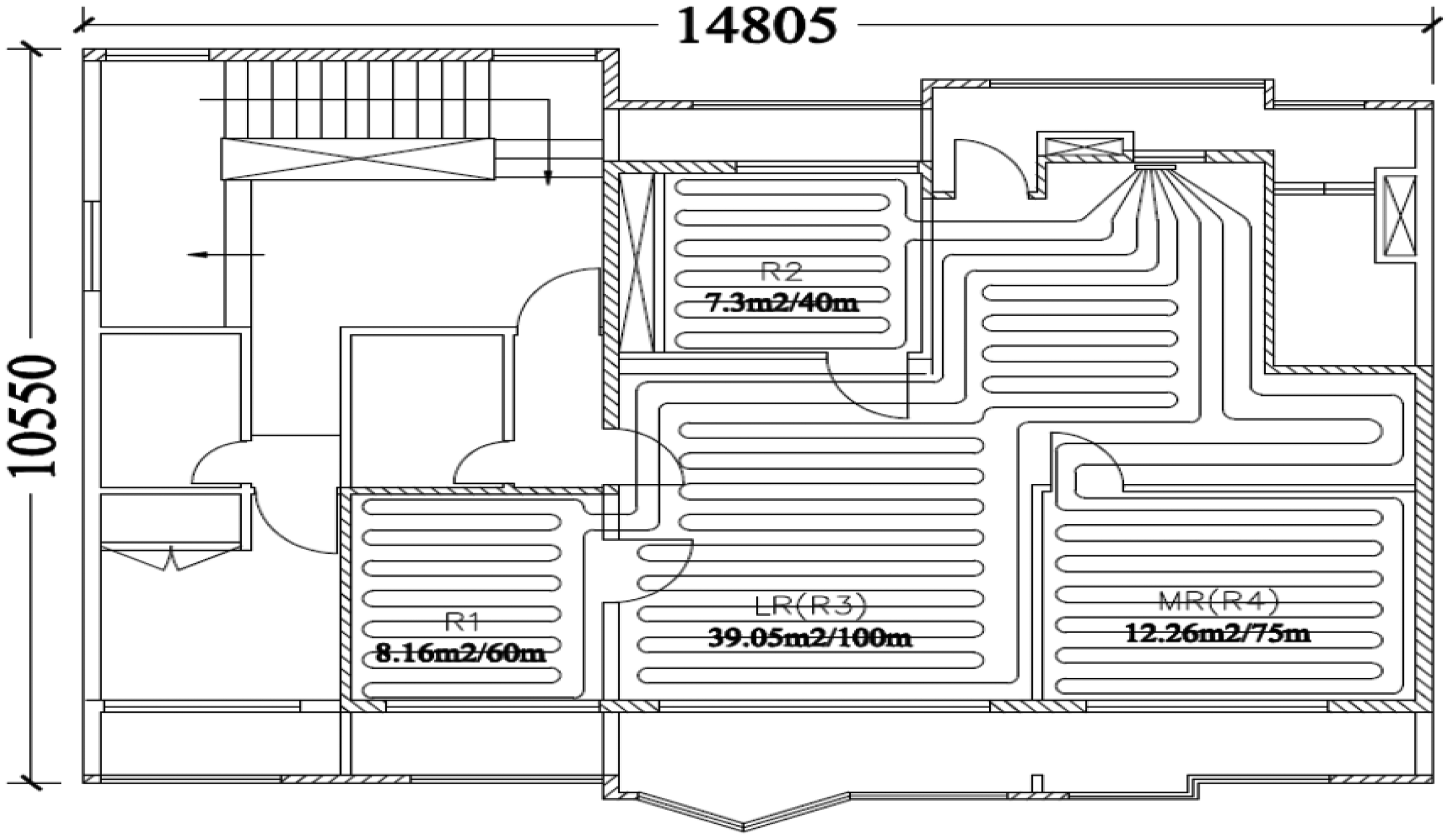
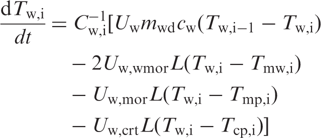
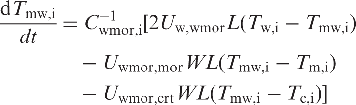
Model equations: the floor slab model
The hot water inside the tube transfers heat to the floor slab from which the heat is released to the zone air by radiation and convention. Thus, the water temperature decreases along the flow direction, which results in non-uniform temperature distribution in the floor slab and slab surface. A slab with dimensions (a) Embedded piping floor slab and (b) node mesh in floor slab.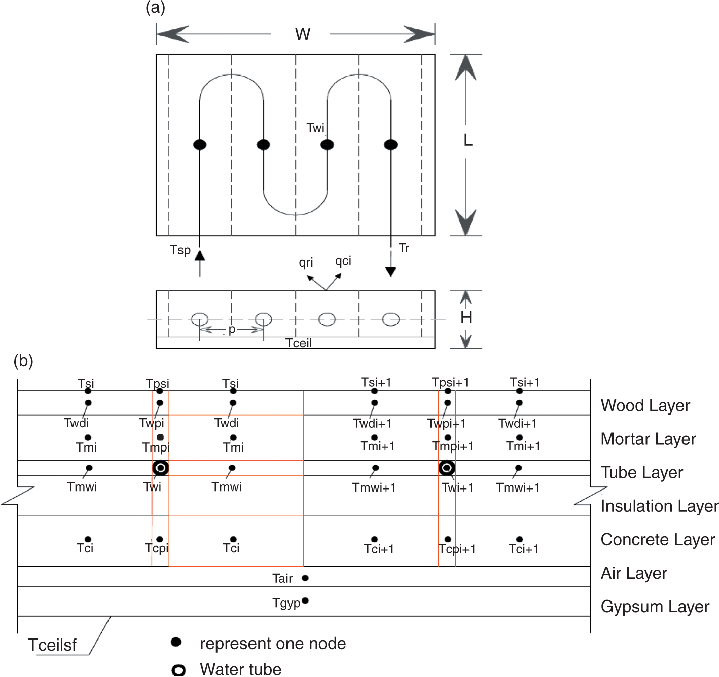
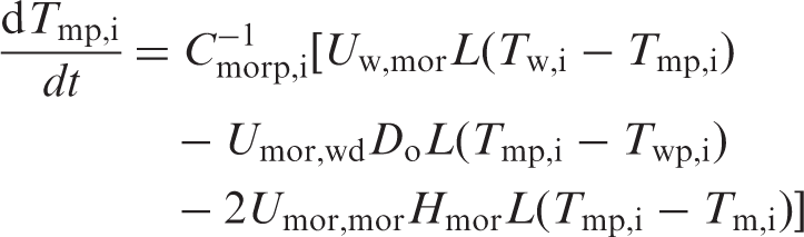
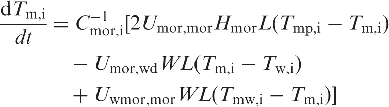
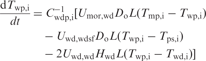
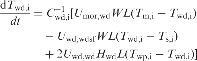
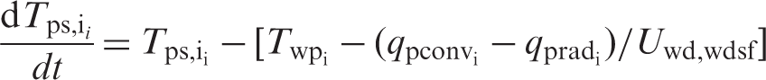
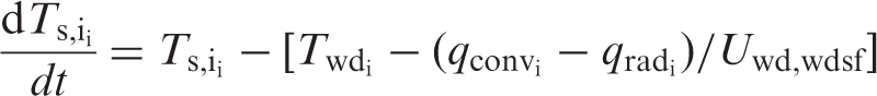
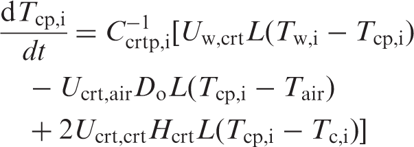
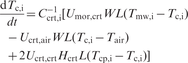
Zone model
The radiation heat flux
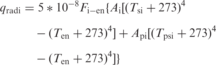
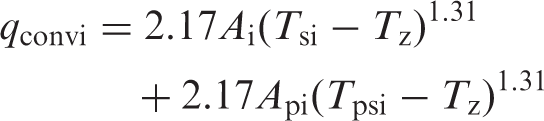

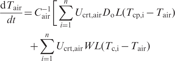
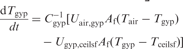
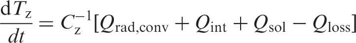
Therefore, the energy balance on the zone air can be expressed as:
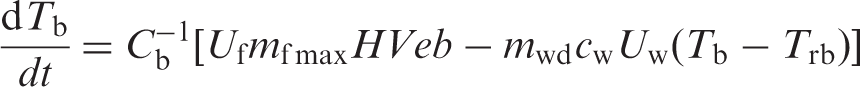
Boiler model
A gas-fired boiler is considered. Assuming the efficiency of the boiler is a function of return water temperature,
9
the energy balance equation on the boiler is:
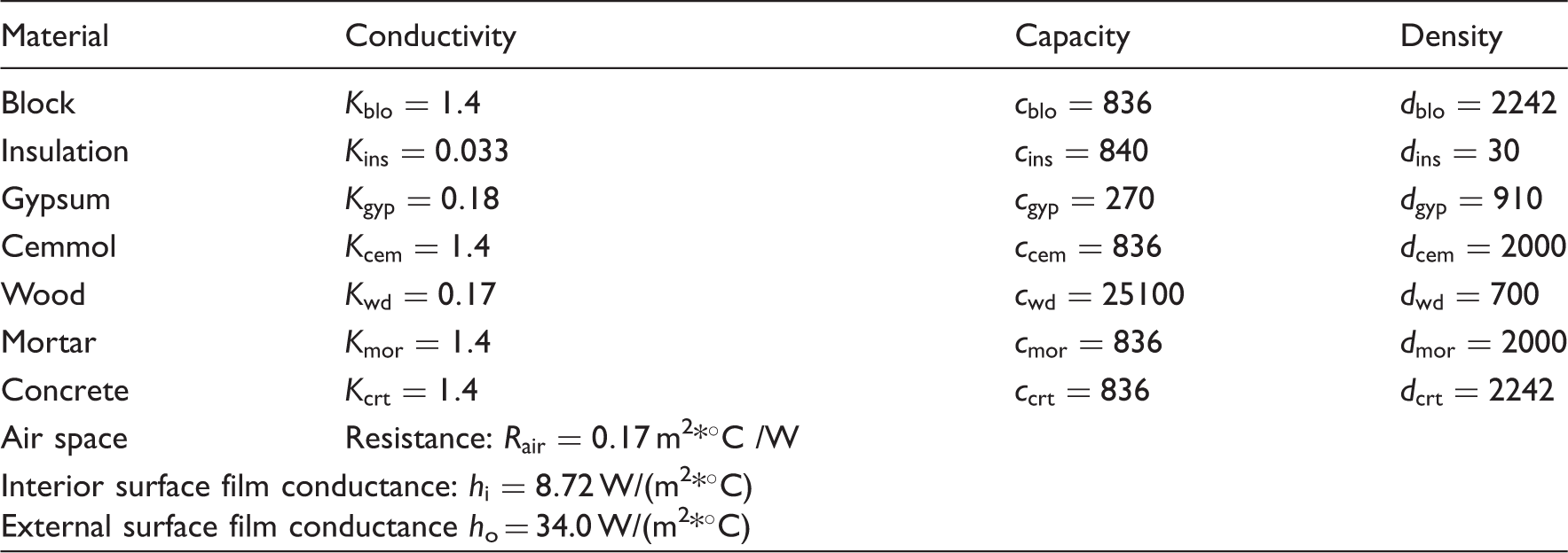
Properties of construction materials.
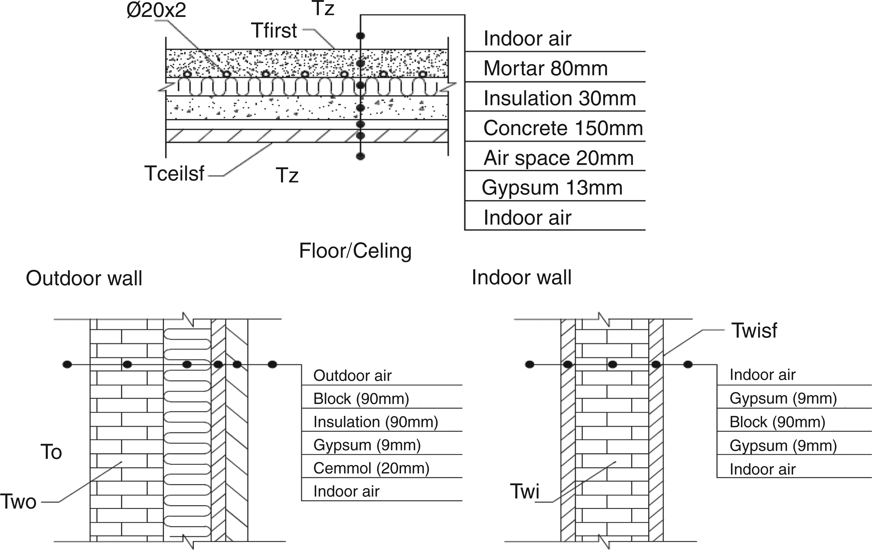
Typical wall and ceiling construction details.
Open-loop responses of the four-zone radiant floor heating (RFH) system.
In the model equations, the outputs are
Optimal predictive control strategy
In order to improve energy efficiency of the RFH systems, an optimal predictive control strategy is developed. In the predictive control strategy, boiler water temperature set-point is predicted according to the variation in the outdoor air temperature. When the outdoor air temperature decreases, the supply water temperature will increase and vice versa. The nature of the functional relationship could determine the effectiveness of the predictive control strategy and it is likely to result in a better energy performance. The predictive control algorithm is described by the following steps:
According to the initial conditions, calculate the heat transfer to the zone:
The heat transfer from the water to the zone According to the predicted heat transfer obtained above, the predicted supply water temperature is computed from: Assuming the supply water temperature By using the supply water temperature Similarly, repeat the calculations to determine According to the supply water temperature series A PI controller is used to regulate the boiler water temperature toward the set-points by changing the fuel firing rate. Likewise, zone air temperature is regulated by changing water mass flow rate by the PI controllers as in the conventional PI control strategy.

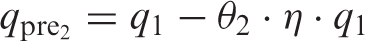
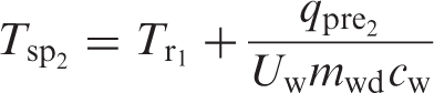
Note that by choosing a proper weighting factor η, the predictive control performance can be improved. This strategy is optimal in steady state and is simple to implement on real systems.
Performance of the RFH system under optimal predictive control strategy
There are five PI controllers in the four-zone RFH system, one of which is used to control the gas burning rate and the rest are used to control the water mass flow rate in the water distribution loop. Figure 5(a) and (b) show the PI control loops and the PI controller block diagram of the four-zone RFH system.
(a) Control loops for the four-zone radiant floor heating (RFH) system. (b) PI control block diagram for the four-zone RFH system.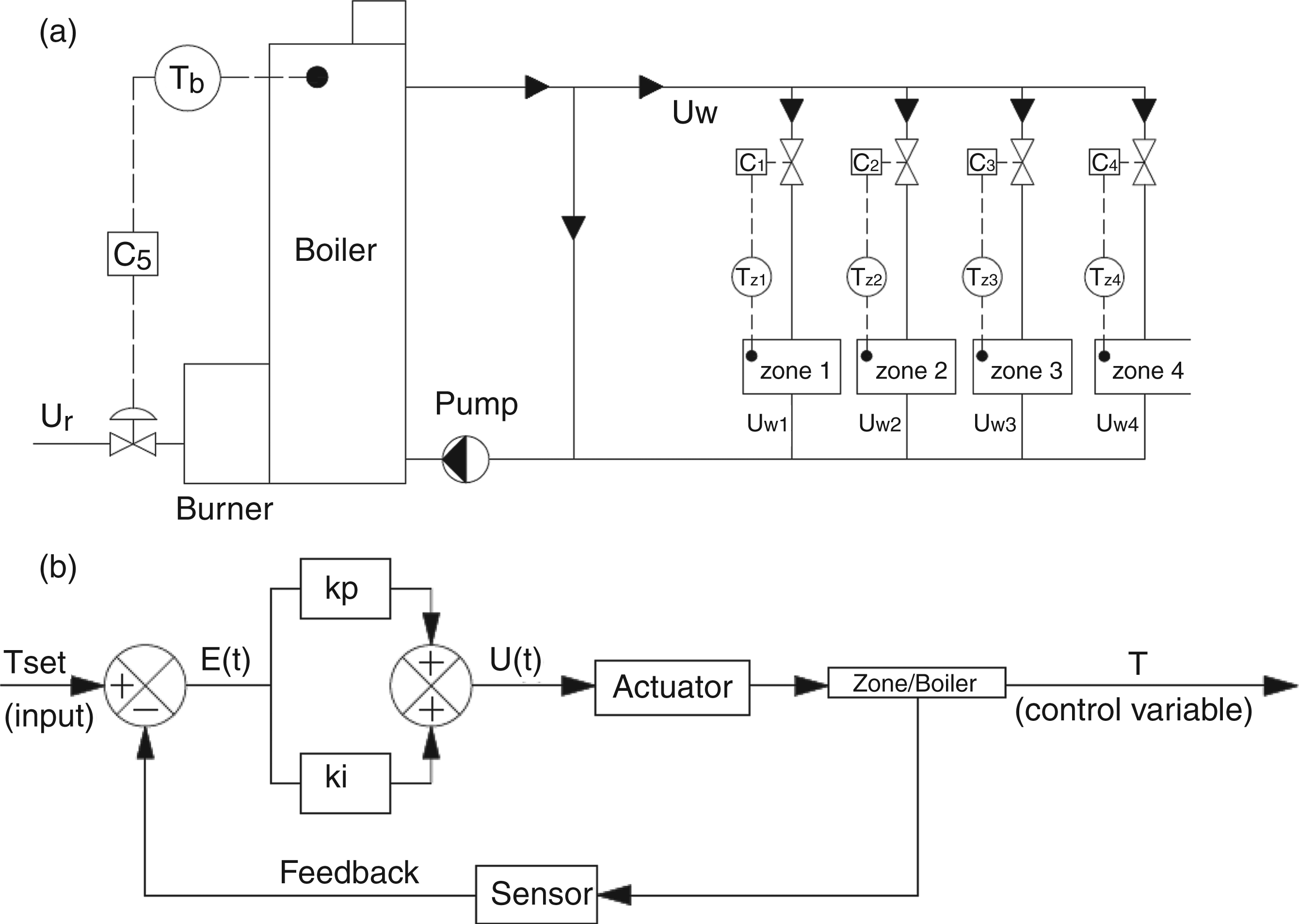
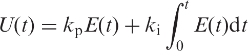
The PI control equations are

Simulation results of the RFH system under optimal predictive PI control strategy
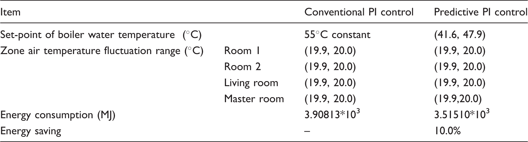
By trying different values of constant gains for the PI controllers and weighting factor η, the following sets that gave good responses were obtained. These are (a)–(j) Optimal predictive control responses.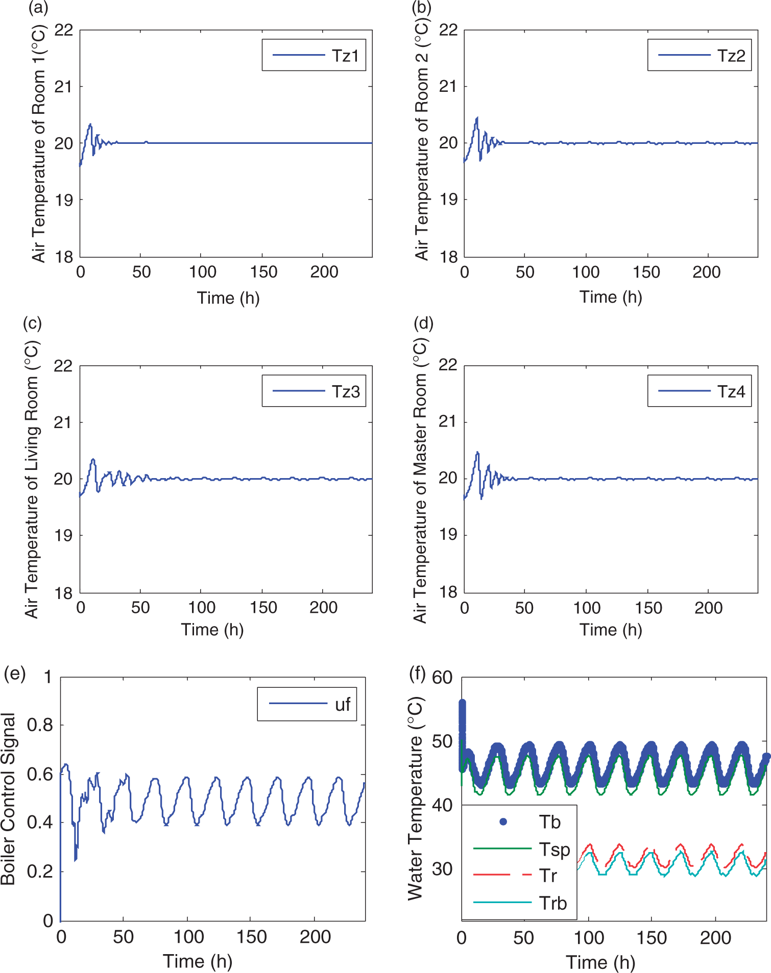
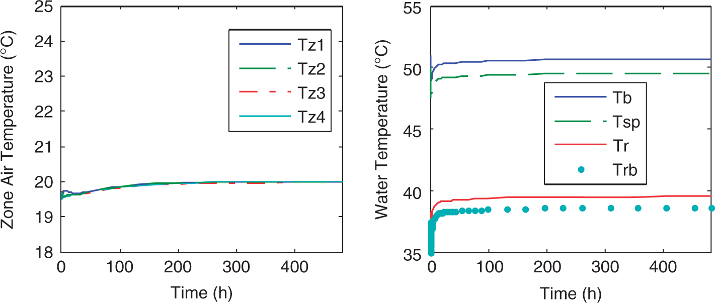
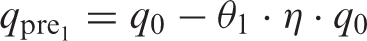
A typical outdoor day temperature was modeled as a cosine function, with maximum temperatures ranging between −10 and 0℃ simulated consecutively over a 10-day period. The simulation results are shown in Figure 6(a)–(j). It can be seen that, under the predictive PI control, the zone air temperatures in all the zones are well-regulated. The zone air temperature fluctuations range between 19.9 and 20.0℃, 19.9 and 20.0℃, 19.9 and 20.0℃, and 19.9∼20.0℃, respectively, in room 1, room 2, living room, and master room. The energy consumption during the simulation period was 3.515*103 MJ.
Comparison between the conventional and predictive PI control strategy
Comparisons between the conventional PI and predictive PI control for the multi-zone radiant floor heating (RFH) system.
Part-2: Experimental study
The simulation results presented above show the significant energy-saving potential of optimal predictive PI control compared to the conventional PI control. The question naturally arises whether such energy savings can be realized in real systems. To this end, an experimental RF-DHS test facility was designed and commissioned. Experiments were conducted to examine the energy performance of the optimal predictive control strategy.
Experimental test facility
A layout of the test facility is shown in Figure 7. The test facility consists of an environmental chamber, two test rooms each installed with an RFH system, a boiler and a storage tank, three heat exchange stations, a programmable logic control panel, and a supervisory monitoring and control system (Figure 8(a)). The test facility simulates both space heating and domestic hot water (DHW) needs of a typical apartment. In this study the experiments conducted on the space heating system will be presented.
Layout of the test facility. (a) Online supervisory control system and (b) schematic diagram of control loops.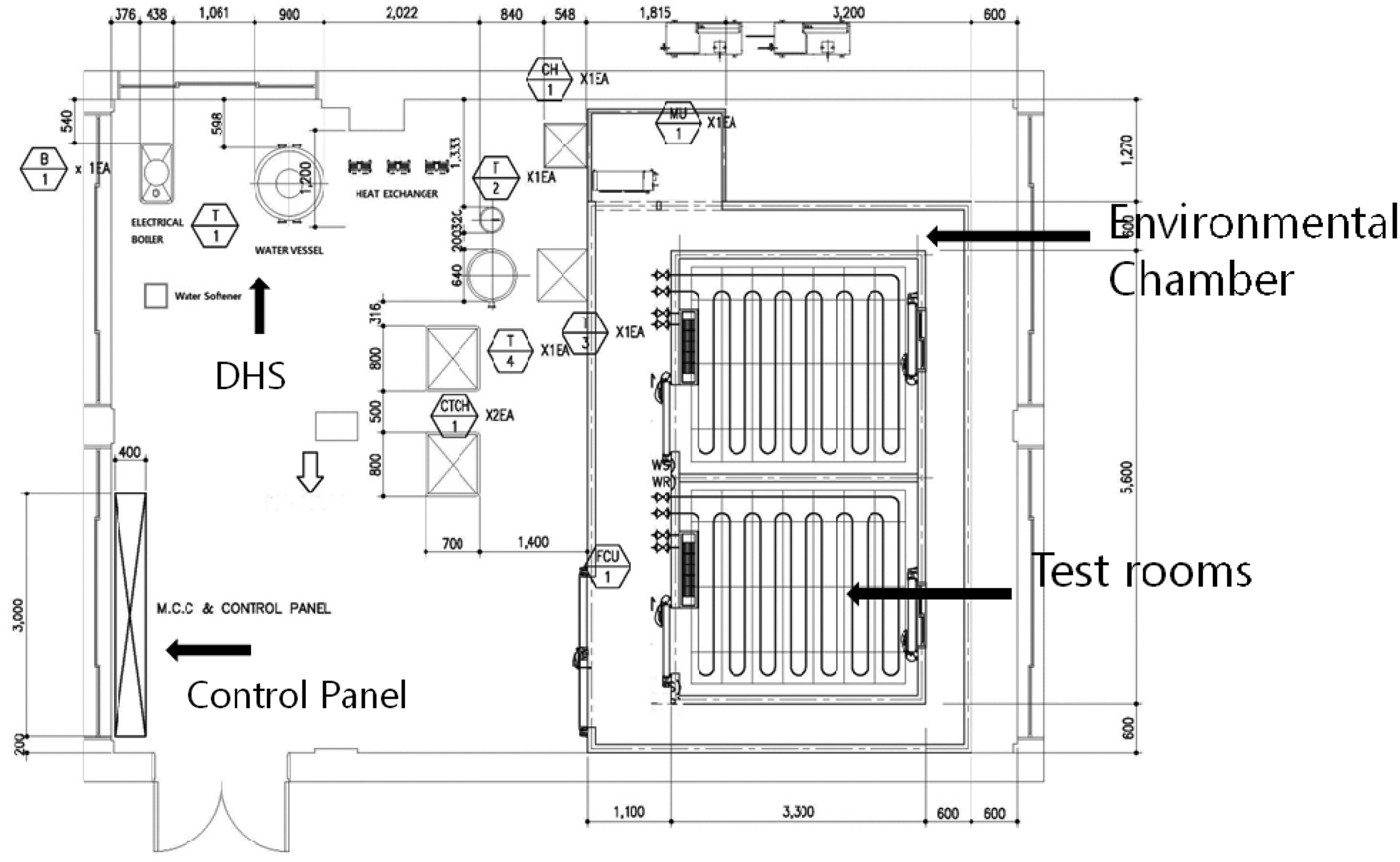
Test rooms
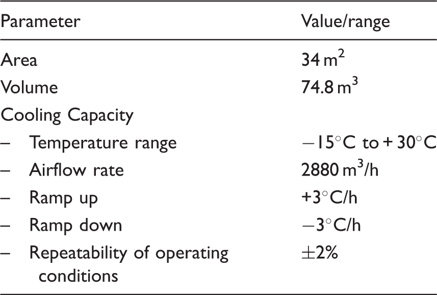
Two identical test rooms each measuring 9.0 m2 were constructed side-by-side. The test rooms were heated by RFH systems as shown in Figure 7. The test rooms consist of a 4 × 4 feet window and a door. The radiant floor slab is 8-inch thick with a ¾ inch diameter PVC pipes embedded in the floor slab on 15 cm center-to-center pitch. The test rooms are installed inside an environmental test chamber that measures 34 m2 in area. Each test room is also equipped with a hot-water fan-coil unit and a 100-cfm outdoor air fan and an exhaust fan to simulate infiltration load on the test rooms. The air infiltration rate in the room was controlled by on/off control of the fan as well as outdoor air lovers. Typical air infiltration rates in the experiment ranged between 0.5 and 1.0 air changes per hour. The fan-coil unit is used as a back-up unit whenever the infiltration load exceeds and space heating from RFH system alone cannot meet the load.
Environmental chamber
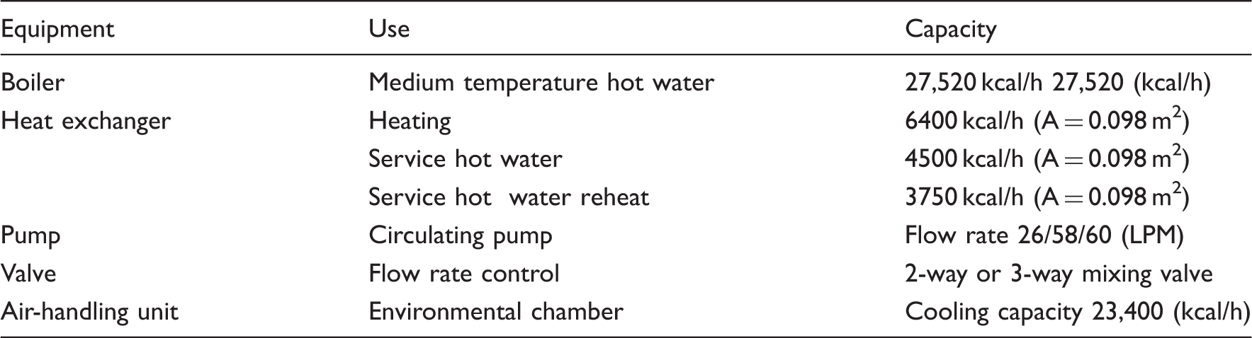
Experimental facility-equipment capacities.
Environmental chamber design/operating specifications.
The laboratory RF-DHS system
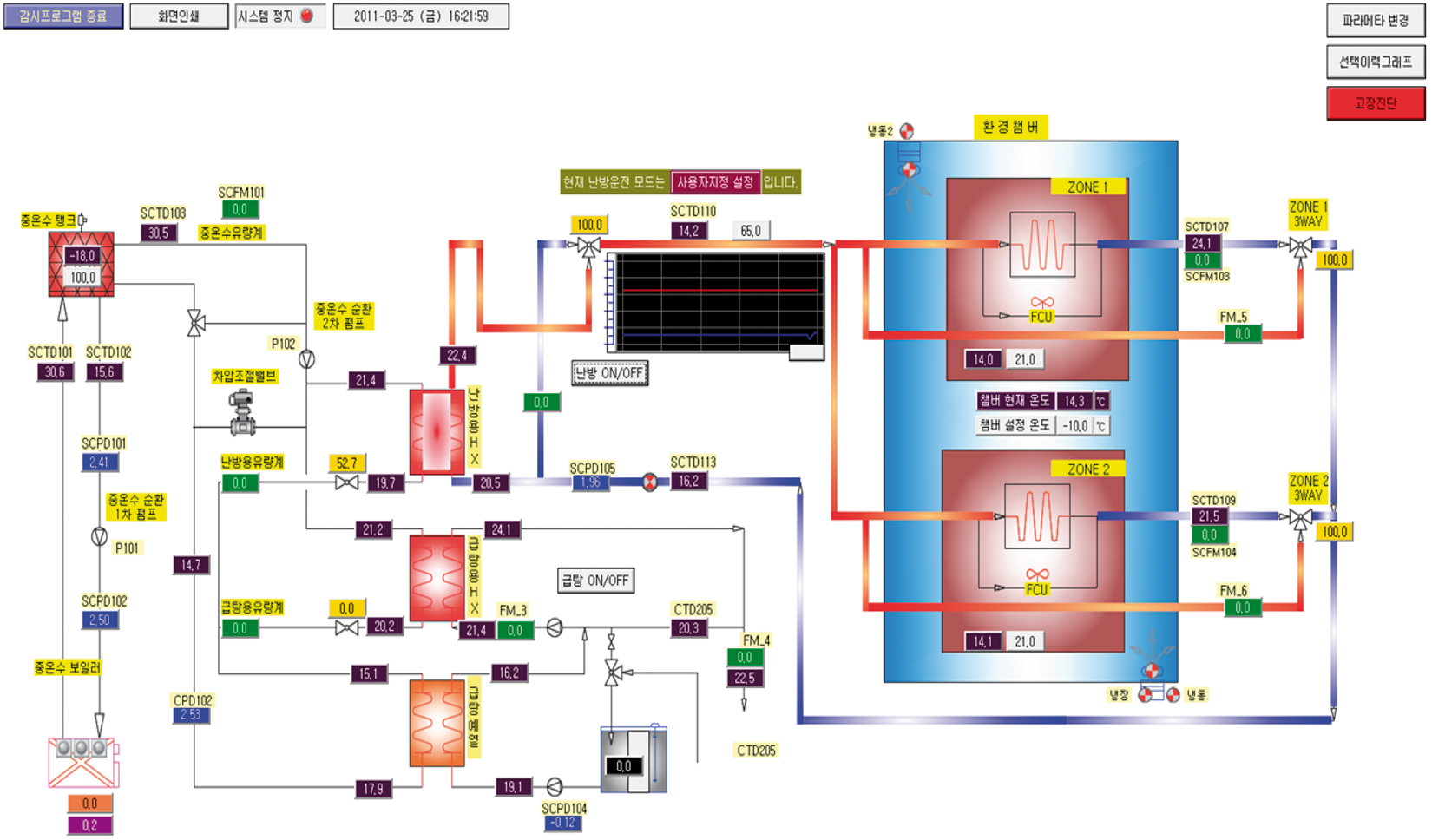
The laboratory DHS system consists of an electric boiler of capacity 27,520 kcal/h, a 500-liter water storage tank, and three heat-exchanger stations: (a) a 6400 kcal/h heat exchanger for space heating, (ii) a 3750-kcal/h pre-heat exchanger, and (iii) a 4500-kcal/h DHW heat exchanger. All heat exchangers were plate-type with an area of 0.098 m2 each. Hot water at 100℃ from the storage tank was supplied to the primary side of the heat exchanger. The secondary side water temperature varied depending on whether it was for the space heating or the DHW circuit. A schematic diagram of the online supervisory control system with sensor/actuator locations is depicted in Figure 8(a)–(b).
Control loops
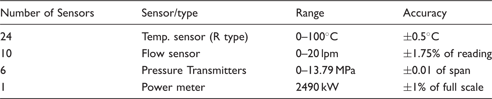
Sensor range and accuracy.
Control strategies
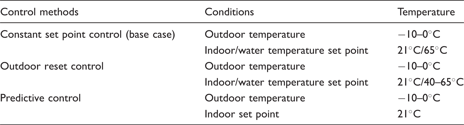
Experiments were conducted to compare the performance of three different control strategies:
Constant set-point control (base case) Outdoor air reset control Optimal predictive control
Control strategies and operating condition.
Constant set-point control
In practice, the temperature set-point of the secondary water circulated in the RFH systems is chosen based on the past experience. This temperature set-point is normally 65℃ and is kept constant. This type of control is referred to as constant set-point control which is considered as the base case in this study. Results from all other control methods were compared with the base case results to determine their relative energy performance. Although not expected to be energy efficient, the base case control is simple to implement in real systems.
The experimental results from the base case control are depicted in Figure 9(a)–(c). The experiments were conducted by simulating a linearly varying outdoor air temperature profile in the environmental chamber. The temperature change was from −10℃ to 0℃ over a period of 6 h. As shown in Figure 9(a) and (b), the temperature differential between the supply and return water temperature on the primary side of the heat exchanger was around 30℃. On the other hand, the water temperature differential on the secondary side of the heat exchanger was about 10℃. The energy consumption over a 6-h period was 2400 Wh as shown in Figure 9(c).
(a) Supply temperature, return temperature, and flow rate of first heat exchanger (constant set-point control, base case). (b) Supply temperature, return temperature, and flow rate of second heat exchanger (constant set-point control, base case). (c) Power consumption (constant set-point control, base case).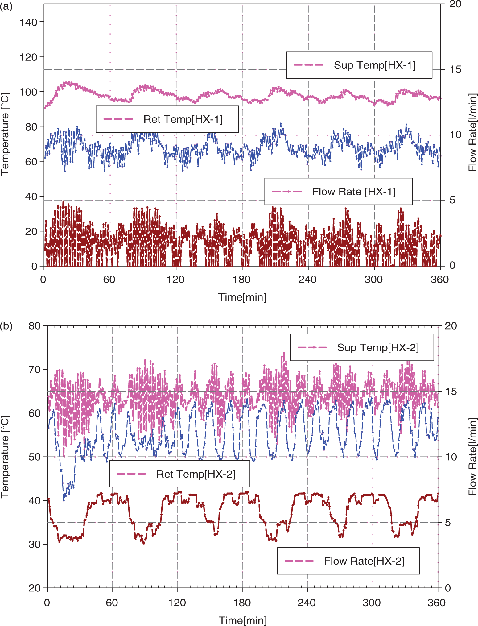
Outdoor air reset control
The outdoor air reset control strategy used in this study is based on real DHS operating conditions used in Korea. In this outdoor air reset control strategy, the supply water temperature set-point is changed as a linear function of outdoor air temperature. In the approach used, the maximum water temperature was set at 65℃ under full load design conditions and the minimum water temperature was set at 40℃. A linear function was assumed with a rate of decrease of about 0.8℃ per degree increase in the outdoor air temperature. The results obtained from the outdoor air reset control are depicted in Figures 10(a)–(c). It can be noted that as the outdoor air temperature is increased, the secondary side water temperature differential decreased. The measured energy consumption in this case was 2250 Wh.
(a) Supply temperature, return temperature, and flow rate of first heat exchanger (outdoor reset control). (b) Supply temperature, return temperature, flow rate of second heat exchanger (outdoor reset control). (c) Power consumption (outdoor reset control).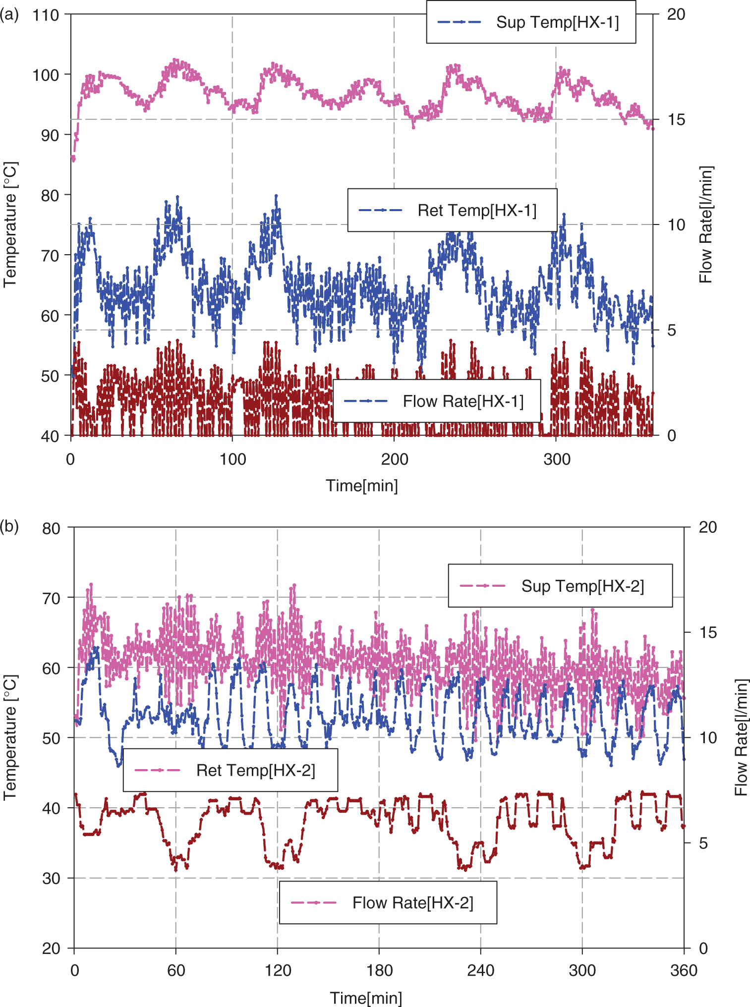
Optimal predictive control
The developed optimal predictive control algorithm was tested under the same operating conditions as the previous two control strategies. The results are shown in Figure 11(a)–(c). As noted from the figures, the local fluctuations in the temperature have reduced and the temperature differential is smaller than the other two control methods. The recorded energy consumption was 2100 Wh. This represents about 12% energy savings compared to the base case.
(a) Supply temperature, return temperature, and flow rate of first heat exchanger (optimal predictive control). (b) Supply temperature, return temperature, and flow rate of second heat exchanger (optimal predictive control). (c) Power consumption (optimal predictive control).
These savings are due to (a) lower temperature differential between supply and return water temperatures which reduces heat losses from the distribution system, (b) slightly lower room air temperatures resulting in the optimal predictive control scheme compared to the constant set-point control scheme as evident from Figure 12(a) and (b).
(a) Comparison of room temperature between base case and outdoor reset control and (b) comparison of room temperature between base case and optimal predictive control.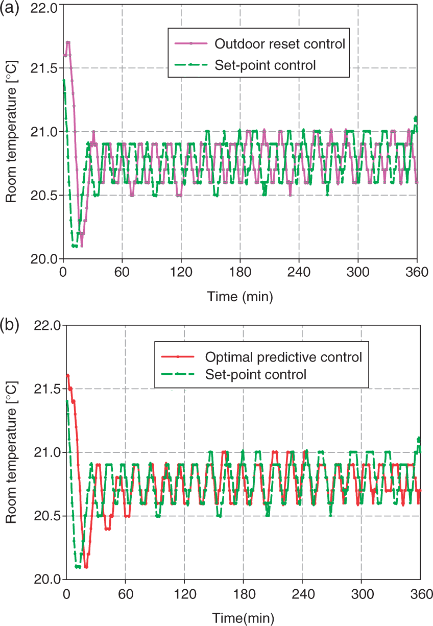
Conclusions
An optimal predictive control strategy for RF-DHSs was developed. The control strategy was implemented on a four-zone RFH system model. Simulation results showed potential energy savings of about 10% compared to the conventional PI control strategy. The energy performance of the optimal control strategy was validated by conducting experiments in an RF-DHS test facility. The experimental results show that the optimal predictive control strategy maintains the supply and return temperatures lower than the conventional control schemes. As a result, energy savings of up to 12% have been achieved. Being simple and energy efficient, the optimal predictive control is a good candidate control strategy for DHSs.