






Abstract
This study presents an innovative concept of a compact integrated solar-thermoelectric module that can form part of the building envelope. The heating/cooling modes use the photovoltaic electrical current to power the heat pump. The experimental analysis was carried out and the results of coefficient of performance were in the range 0.5–1 and 2.6–5 for cooling and heating functions, respectively. The study demonstrates that thermoelectric cooler can effectively be used for heating, ventilation, and air conditioning applications by integrating with solar panels especially in cooling applications. The system is environmentally friendly and can contribute in the implementation of zero energy buildings concept.
Introduction
Energy consumption in buildings whether for domestic or commercial purpose has a major portion attributed to heating, ventilation, and air conditioning (HVAC). The cooling requirement in HVAC systems is energy intensive as compared to the heating and ventilation requirements. Air conditioning for hotter regions and severe climatic temperatures is a round-the-clock requirement with heavy energy consumption during the day-time hours owing to the hotter temperatures. Consequently the regions with higher temperatures also have a higher solar irradiance resulting in good potential for solar power utilization either for direct use or for electric power generation. In this context, thermoelectric effect can play an important role in either of the two requirements, i.e. the available high temperatures can be used for the provision of a temperature gradient for power generation through the thermoelectric cells or electricity obtained directly from solar photovoltaic (PV) panels can be used to draw heating/cooling effect from the thermoelectric cells. Energy consumption in HVAC applications varies according to the regions. It ranges from 25% to 35% in Europe and US, 1 while for tropical countries it can reach as high as 56% in residential buildings. 2
A number of studies have discussed the potential of thermoelectric coolers (TECs) and thermoelectric generators (TEGs) in reducing the energy consumption for HVAC applications. Patent for thermoelectric air conditioning apparatus has been registered as early as 1963. 3 In this regard, the integration of renewable energy, the most common being solar energy has also been investigated by some researchers. Vella et al. 4 initialized the first concept of solar energy-based thermoelectric refrigerator in 1975. A modern concept in solar thermoelectric refrigeration was given by Abdul-Wahab et al. 5 Jugsujinda et al. 6 has analysed the performance of thermoelectric refrigerator. Abdullah et al. 7 investigated the performance of a combined solar-thermoelectric-adsorption cooling system. Su et al. 8 have evaluated the performance of thermoelectric refrigerator driven by dye-sensitized solar cells.
A number of studies have also been carried out that focus on the green building applications and the building envelopes. The building envelopes can be integrated with solar panels or solar roofs as these are the surfaces that face the maximum incident radiation. Similarly for windows, the active building window system is a new window technology which integrates photovoltaic and thermoelectric technologies.9–11 This technology has a low efficiency range with about 5% in cooling mode and 13% in heating mode.
The recovery of energy is another method for improving the energy consumption in buildings. Energy recovery technologies are able to improve the energy efficiency and have been widely applied in different energy system. General energy recovery technologies mainly include absorption refrigeration, 12 liquid desiccant technology, 13 thermoelectric cooling technology 14 and heat pipe heat exchanger. 15 Thermoelectric cooling systems have no mechanical moving parts and do not employ working fluids that are harmful to the environment, which can transfer heat from the cold side of the modules to the hot side with consumption of electricity. Solar thermoelectric air conditioner with hot water supply employs condensing heat recovery in vapour compression air conditioning systems and has been applied in many engineering projects.16,17
Literature analysis
The global energy consumption is forecasted to rise by 34% in the period 2014–2035, with the greatest chunk being taken by the fast growing economies.
18
It has also been identified that majority of these emerging and growth leading economies (EAGLE) nations are located in warm climatic zones and have high urban population and growth.
19
The dense urban growth and consequent demand of cheaper HVAC applications imply that technologies be developed that are based on renewable energy and can be easily integrated into the building envelope. The availability of abundant daily and yearly solar radiation has renewed interest in solar cooling technologies.
20
A number of research projects have focused on the solar cooling systems with PV panels as the prime power generation device.21,22 In this regard, a few efforts have also been directed towards the development of building components that integrate the solar cooling devices. Among the different technologies that can be integrated with solar cooling is the thermoelectric device that is based on Peltier effect. When two different metallic conductors are applied with direct current, a change in temperature is observed. The reversal of current reverses the direction of heat flow and consequently heating and cooling effect is obtained. Thermoelectric modules consist of P-type and N-type semiconductors, as direct current flows through these modules, the temperature on one side decreases thereby allowing absorption of heat. The other side has a rise in temperature and heating effect can be achieved from this side. The Peltier effect is shown in Figure 1.
Functioning of thermoelectric module.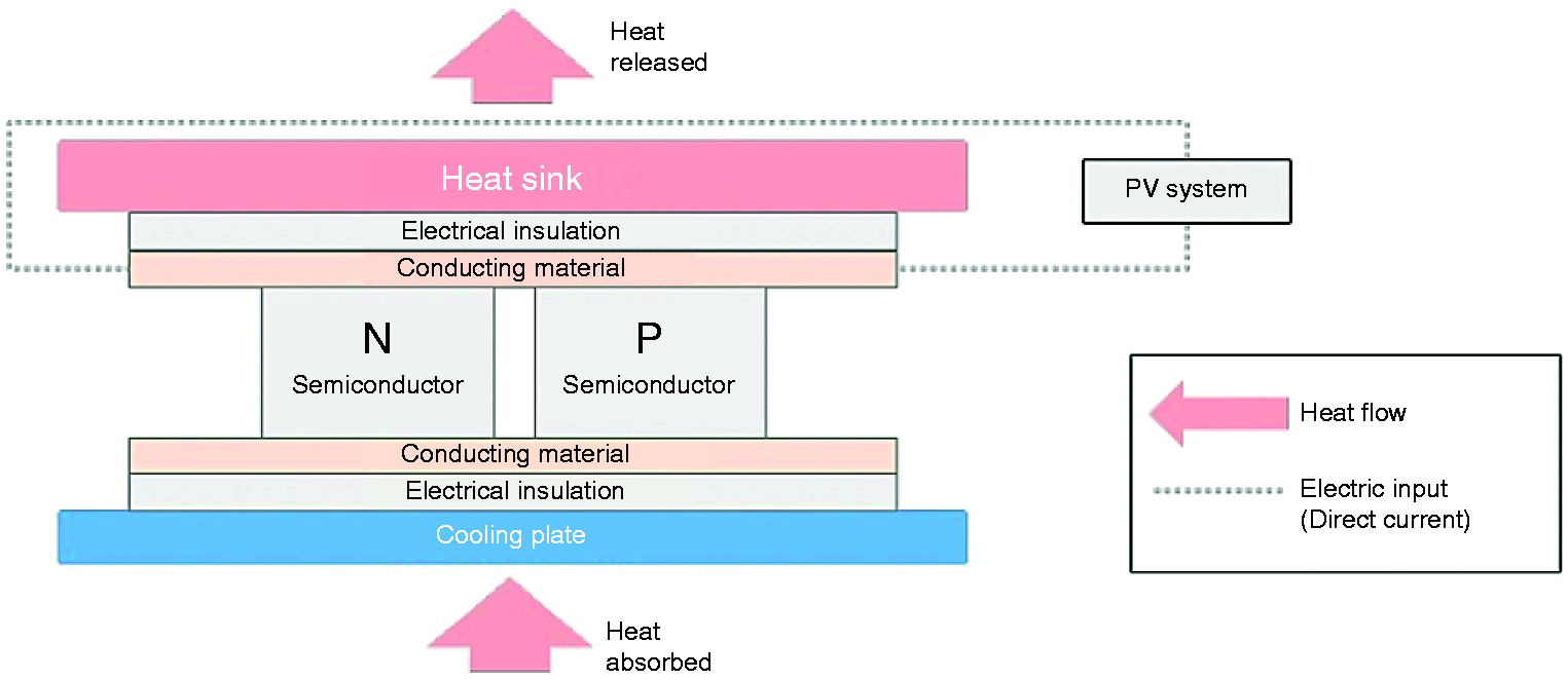
The Peltier modules are used in conjunction with solar PV cells for the provision of DC current to achieve heating and cooling effect. Khire et al. 23 first devised the active building envelope (ABE) that uses solar energy along with TE modules to compensate for passive heat losses or gains in buildings. This study optimized the design configuration of TE unit based on two objectives viz. the total power input required and the number of TE coolers required. In 2007, Xu et al. 24 studied the performance of thermoelectric modules for use in ABEs. This study determined the coefficient of performance (COP) of the commercially available TE modules along with PV panels under different voltage regimes. The study concludes the most suitable type of TE modules, the voltage and current, and the preferable connection diagrams. ABE window systems were evaluated by Xu and Van Dessel 25 to determine the number and type of electrical connections for the TE modules to pursue the maximum power point for PV operation.
In 2015, Liu et al.
26
developed a concept of active solar thermoelectric radiant wall (ASTRW) that integrated thermoelectric radiant cooling and PV technologies. In this concept, the heating or cooling effect is carried out by attaching a plate of aluminium to the hot or cold side of the TE device depending on the heating or cooling requirement. This radiant aluminium plate is embedded in the inner side of the building wall towards the inner environment. The construction is shown in Figure 2(a).
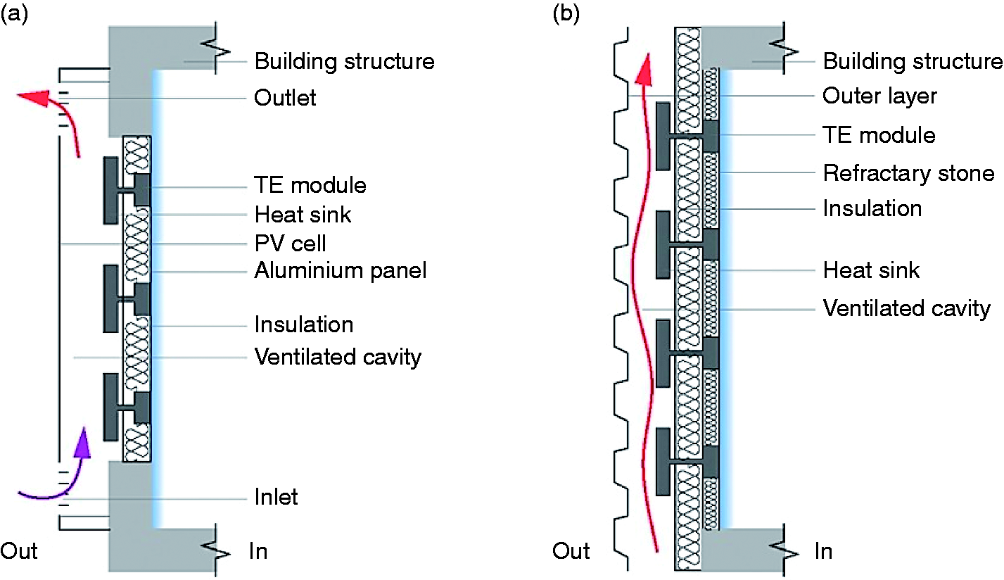
The façade is also provided with an externally ventilated cavity within which the heat sinks are also present. The outer side is provided with a solar panel that operates the complete system. Figure 2(b) depicts the design modification carried out by Ibanez-Puy et al., instead of the outdoor solar panel; a trapezoidal steel sheet is installed for testing purposes. The study discusses the number and type of electrical connections for the TE modules to achieve excellent performance. The working principle of the concept developed by Ibanez-Puy et al.
27
follows the same principle explored by Liu et al.
26
Correspondingly, the solar thermoelectric model developed by Xu and Van Dessel
25
differs in construction to that developed by Liu et al.
26
in the medium employed for heat transfer. The Xu and Van Dessel’s
25
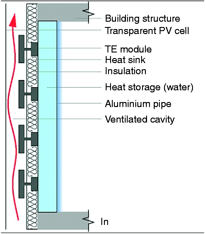
model is in the form of a window with an external transparent PV layer that acts as the energy generator without blocking the external view. Two opaque modules placed on the sides of the window contain four TE units that are connected to external heat sinks. On the inner side, the TE units are connected to aluminium tube filled with water which is insulated on all sides except the side facing the inner environment, for the delivery of cooling effect. Figure 3 shows the construction.
Water-based thermoelectric cooling module. Image taken with permission.
25
The model proposed in the current study is novel in this aspect that it integrates the solar panels and the thermoelectric units in a ventilated module that has three independent cavities. The heating or cooling effect is transferred to the indoor environment through an exclusive inner cavity. The two cavities on the outdoor side provide a more efficient form of heat dissipation through the heat sinks and also assist in bringing down the temperature of the solar panels. The efficiency of the PV cells has been observed to reduce with the increase in temperature. 28 Efficiency improvement of PV cells has been achieved in this novel model through ventilation. A good COP has been attained by incorporation of these novel measures.
Integration of TECs and solar PV
This study presents an innovative concept for utilization of thermoelectric heat pumps in the building walls by integration with solar PV cells. In most countries of the South, the solar radiation is in the range 1300–2500 kWh/m2 as shown in Figure 4.
29
Thermoelectric heat pumps can be operated with the electricity derived from PV panels. The TEHP as well as the PV electricity generation is a mature technology and both cooling and heating can be achieved in buildings with the reversal of current direction. Moreover, TEHPs as well as solar PV cells have no moving parts and hence the power generation is totally emission free.
World solar energy map.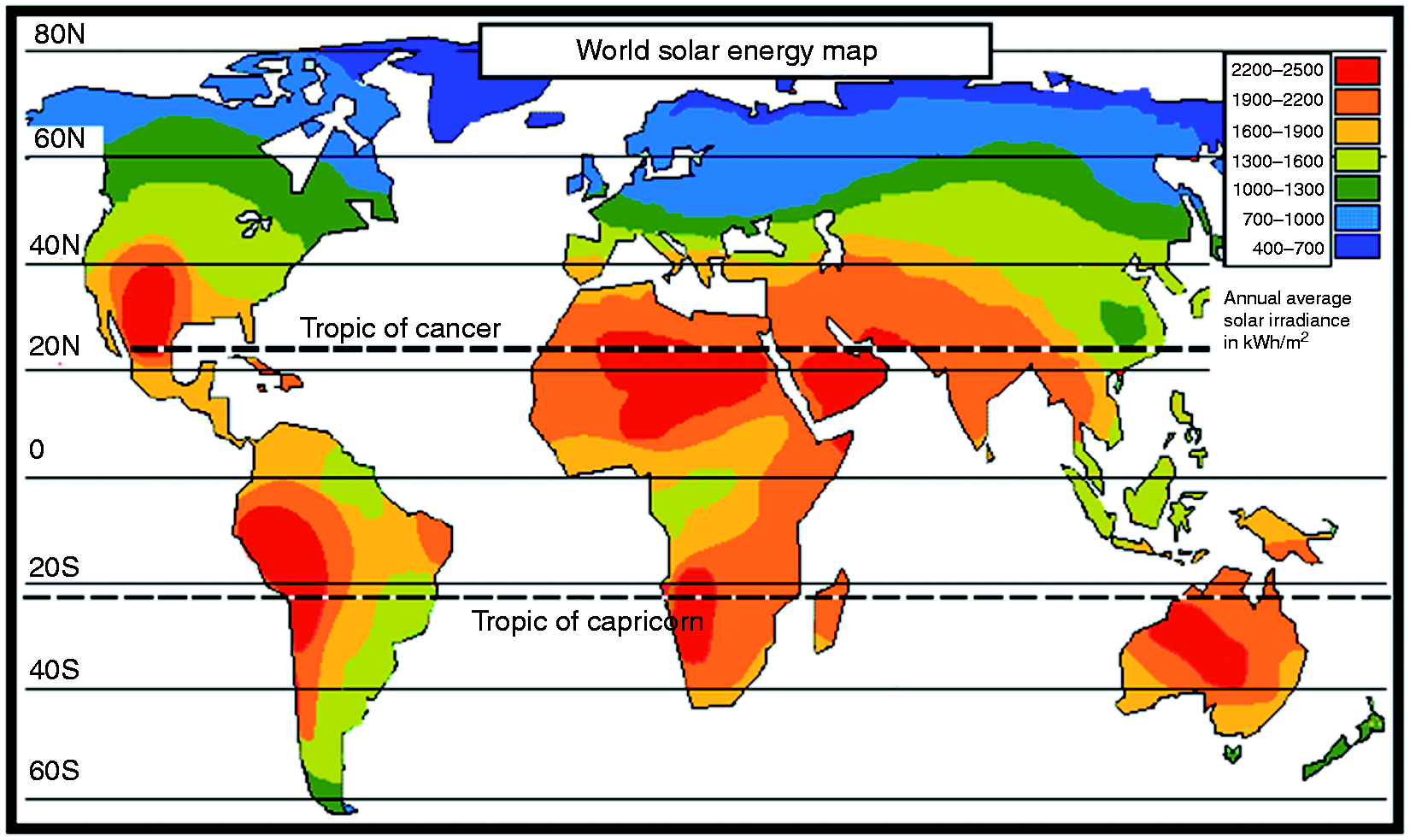
In all building infrastructures whether commercial or residential, the front walls are usually provisioned to have doors or windows that can hold the integrated system of TECs and PV cells as discussed below.
If these walls are provisioned for ventilation then the installed PV cells can work with a higher efficiency, because of the lowering of PV cell operating temperatures.
Construction of the active building wall
The outer wall of the building integrates the PV-TEHP system as it faces the solar radiation. The system is proposed to be of modular type depending upon the length, width and height of the building. A single-storied building with a broad front can have a larger number of modules fitted into it as compared to one that has a narrow front. It is estimated that a wall thickness range of 15–20 cm is able to integrate the components of this module. The construction of the PV-TEHP module is as shown in Figure 5. The module consists of three air-conduits partitioned by walls. The outer most surface facing the sun or the environment is constructed of the PV solar panels with necessary strength afforded by reinforced insulated material. Conduit 2 and conduit 3 are separated by a wall containing the thermoelectric heat pumps. The ventilation in conduit 1 and conduit 2 allow for a higher thermoelectric heat pump performance by reducing the temperature difference across the thermoelectric heat pump as demonstrated in the succeeding text. This PV-THEP module has two operating modes, i.e. the cooling and the heating mode.
Construction of PV-TEHP integrated module.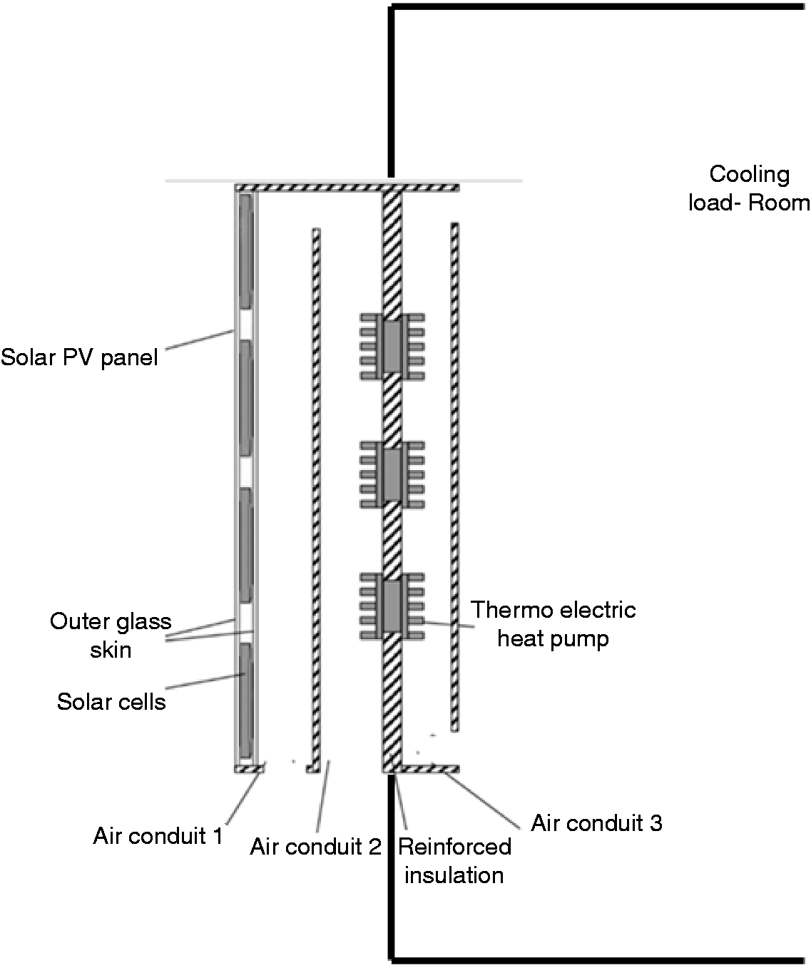
Cooling mode
In cooling mode, the outside air has parallel flow in conduit 1 and conduit 2. Air passing through conduit 1 has the effect of cooling down the solar PV cells thus improving their efficiency. Air passing through conduit 2 serves as the heat sink for TEHP. The TEHP is operated by the solar PV cells and indoor air is cooled as shown in Figure 6. The air in conduit 3 may travel downwards in a natural circulation mode; however for forced circulation addition of low-power fans at three points can improve the efficiency of the system. Fan 1 and fan 2 suck the outside air and direct it towards conduit 1 and conduit 2, the air entering conduit 1 absorbs heat, while cooling down the solar panels as it rises up and is exhausted through the damper at the top. Fan 3 directs the indoor air through conduit 3 which is cooled down by rejecting heat as it passes over the TE heat pumps.
PV-TEHP in cooling mode.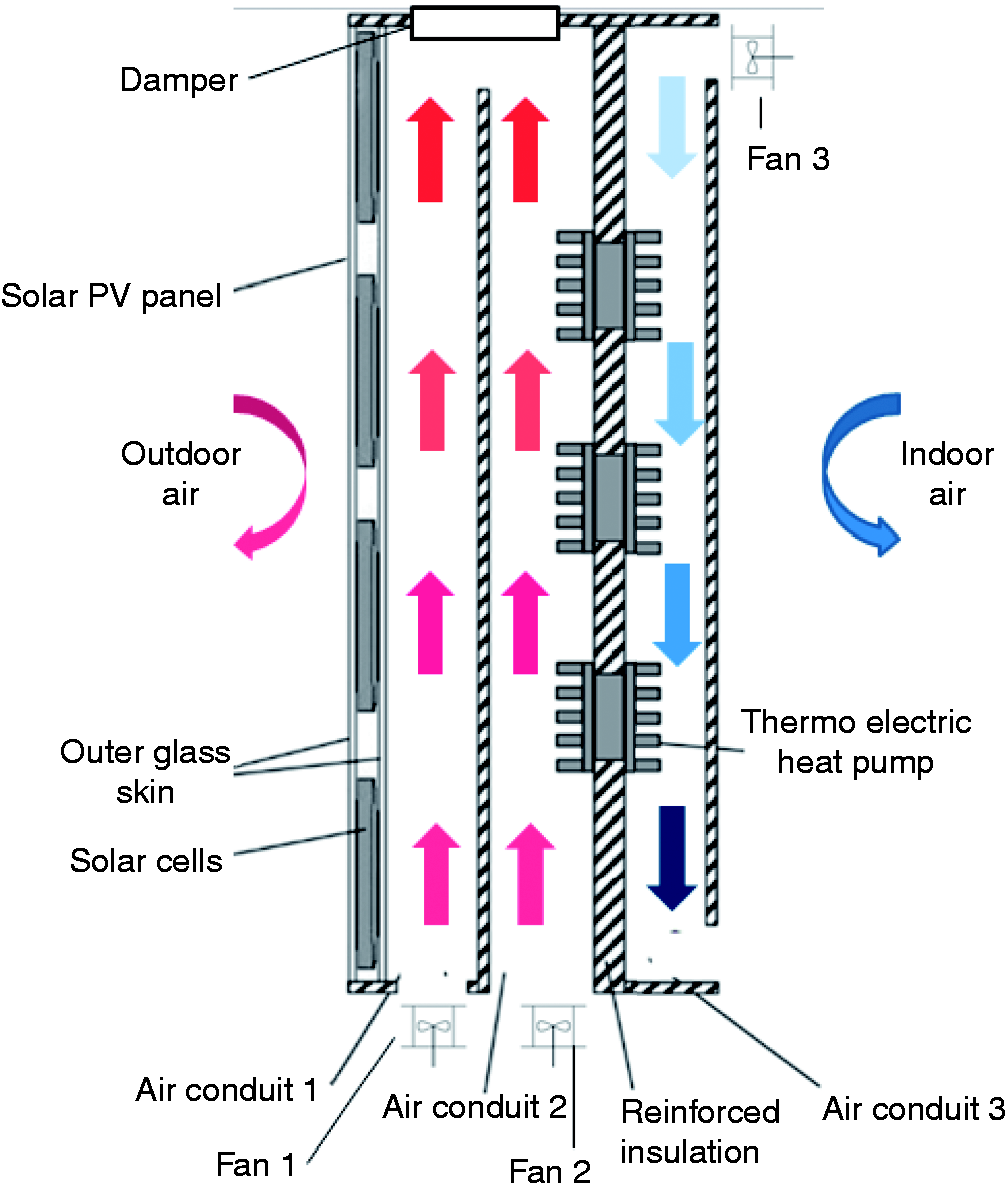
Heating mode
In heating mode (Figure 7), the direction of current is reversed for the TEHP, such that the indoor environment now serves as the heat sink. Cold air enters at the bottom through conduit 3 and as it rises up it is gradually heated up by TEHP. The damper at the top of conduit 1 and conduit 2 is permanently closed during the winter season and cold air entering from conduit 1 is heated by PV cells. On reaching the top of conduit 1, the air is directed towards conduit 2. This also has the effect of cooling the PV cells thereby increasing their efficiency. The current generated by solar panels activates the TEHP and the indoor air is heated up. The performance of TEHP is dependent on the temperature of air entering conduit 2. In the heating mode, if the temperature of indoor air is greater than the temperature in conduit 2, the heating COP as well as the heating capacity is improved. Thus the heating of air by solar panels in conduit 1 is also beneficial for the TEHP performance.
PV-TEHP in heating mode.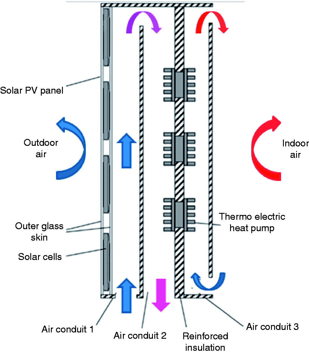
A number of investigations30–32 have noted that the COP of a TEHP has been observed to improve as the temperature difference is reduced. The same is graphically shown in Figure 8.
COP vs. temp difference.
33
Image taken with permission from Riffat and Ma.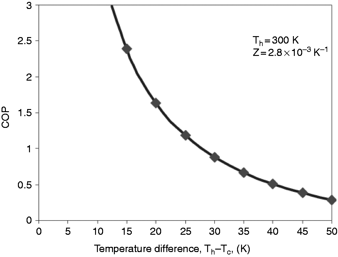
Thus the outdoor cold air entering conduit 1 absorbs heat from the solar panels and enters the conduit 2 with a comparatively higher temperature, thereby reducing the temperature difference between the indoor air and outdoor cold air.
Similar to the cooling mode, in the heating mode also, the use of fans for forced circulation can increase the overall efficiency of the system. In this regard, low-power fans can be installed at the entrance of conduit 1 and conduit 3.
Discussion and improvements
The PV-TEHP module has the potential to be developed into an innovative application for building walls in the urban environment. It has the ability to not only generate electrical power but also to provide environmental comfort through space cooling and heating. The existing HVAC systems have an inherent inertia of fluids, which is of two types: the ‘volumetric inertia’ that requires energy to drive the refrigerant in the HVAC circuit and secondly the ‘thermal inertia’ which is a material property related to thermal conductivity and volumetric heat capacity. Unlike the conventional HVAC systems, the TEHP systems only have a reversal of current for change of cooling/heating mode. This is especially convenient in regions and periods where space heating and cooling is required within the same day. TEHP systems are devoid of any moving parts, hence negligible maintenance is required, are compact in construction and their operation is completely noiseless. These systems also have a high degree of reliability as there is no risk of breakdown or wear of moving parts. Moreover, in the absence of any chlorofluorocarbons (CFCs) the system is environmentally friendly.
As regards the buildings, the TEHP system has the overall effect of reducing the thermal load of the building as this system would replace the traditional elements of building envelope such as the windows, ventilators and other light and air passages. The thermal load of a building can be assessed by various parameters including the building heat loss coefficient which is generally calculated by using the steady-state thermal performance of the building envelope, i.e. U-value, plus additional losses for thermal bridges. Besides the U-value, the material bulk properties of heat capacity (C), density (ρ) and thermal conductivity (λ) play an important role in the cyclic performance of the construction, which is significant when the outdoor temperature is cycling below and above the desired indoor temperature. Although the material properties are significant to evaluate the construction of the proposed TEHP, however the same being an exhaustive discussion is beyond the scope of this study.
As the current study is concerned with the replacement of the building elements with a solar thermoelectric module (STEM) system, there is a downward shift in the thermal load of the building. In Europe, the average U-value for external walls is estimated at 0.625 W/m2℃. This considered along with the number of heating degree days which is 3075,
34
the amount of savings in heating requirements for a year equals to 45 kWh (from equation (1)) for each m2 of the proposed STEM system

The novel STEM system enhances the overall energy performance of the building by providing heated air in the buildings.
The power generation feature of the PV-TEHP module results in an increase in efficiency of the solar panels by almost 10% due to the ventilation effect achieved through the air flowing in conduit 1. This is because of the established fact that the efficiency of the solar panels decreases as the temperature of the solar panels increase. The impact of temperature on solar panel efficiency is known as the temperature coefficient and is specified by the manufacturer as pMax. This value, which is normally given in the form of negative percentage, reveals the impact of temperature on the panel.
Solar panels are power tested at 25℃, so the temperature coefficient percentage illustrates the change in efficiency as it goes up or down by a degree. For example, if the temperature coefficient of a particular type of panel is −0.5%, then for every 1℃ rise, the panels’ maximum power will reduce by 0.5%.
So on a hot day, when panel temperatures may reach 45℃, a panel with a temperature coefficient of −0.5% would result in a maximum power output reduction of 10%. Conversely, if it was a sunny winter’s morning, the panels will actually be more efficient.
Figure 9 indicates the effect of ventilation on the efficiency of the solar panels. When the TEHP module is operating in the heating mode, the temperature of air flowing in conduit 1 is increased by 10–20℃, resulting in an approximately 20% increase in the heating capacity of the PV-TEHP module (keeping in view the performance curves of TEHP) in comparison to the direct use of outdoor air. This also further depends upon the solar radiation incident on the solar panels.
Solar panel efficiency and ventilation.
35
Reprinted from Yun, McEvoy and Steemers with permission from Elsevier.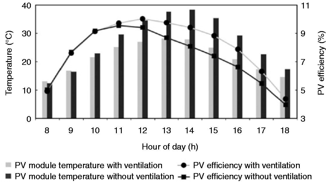
Many countries of the world including Europe (Central & South) and south Asia require heating as well as cooling during the year. In these regions, the heating and cooling loads fluctuate from North to South. In northern and central, Europe and sub-continent, the buildings have higher loads for heating than for cooling, due to colder climates. Similarly, the Southern Europe and tropical regions of Asia have higher cooling needs. The control of this TEHP module has to be made according to the local climatic conditions. For instance, at times when the cooling requirement exceeds the heating requirement, the amount of electricity generated by the solar panels during the heating period would be much greater than the electricity required for generating heat. In such cases, the surplus electricity can be used in other building loads. Thus the strategy has to be matched according to the building load and the weather requirements. The TEHP can also be integrated with a battery storage system to store the surplus electricity.
Among other parameters, the TE devices’ performance is dependent on the type of material used in its manufacture. The TE performance is closely related to the figure of merit of thermoelectric materials, ZT, where T is the operating temperature and Z relates the Seebeck coefficient with the electrical resistivity and thermal conductivity of the material. The TE modules used in the present researches have a ZT of about 0.6–0.7, which is not high considering the progress of TE technology.
Commercially bismuth telluride (Bi2Te3) is considered the most efficient material for thermoelectric applications. 36 However, with the inroads in nanotechnology, a figure of merit up37 to 1.5 has been achieved. On the other hand, the COP of a thermoelectric material is dependent upon the electricity being supplied to the device and the temperature difference across the hot and the cold sides. It is important that a minimal difference is kept between the heat source and the heat sink, while it is equally important that the electricity is regulated so that maximum COP is achieved.
For the cooling mode, if the figure of merit has a moderate value <1, then a COP of >1 can be achieved. In the heating mode, COP up to 3 can be achieved with the available materials with good figure of merit.
Performance indicators.

Performance investigation of TEHP
This part carries out an experimental investigation of the TE heating and cooling unit. The construction of a TE module is comprised of thermoelectric elements electrically connected in series and thermally connected in parallel. As the PV cells supply DC voltage to the TECs, the cooling effect is produced by the Peltier effect. Similarly the Seebeck effect results in a voltage caused by the temperature difference between two dissimilar semiconductors. The mathematical relationships are given in equations (2) and (3), respectively.
38
Equation (4) relates the Seebeck and Peltier coefficients. 


T represents the absolute temperature in Kelvin. The performance of the thermoelectric modules is gauged by a parameter termed as ‘figure of merit’. Higher figure of merit ‘Z’ implies better performance

σ is the electrical conductivity (Ω−1 m−1)
k is thermal conductivity (W/mK)
Commercially thermoelectric modules are comprised of materials that have higher electrical conductivity and lower thermal conductivity. Practically the figure of merit ZT can range from 0.8 to 2.5. It can further be improved by different methods discussed in relevant literature;39,40 however, it cannot be increased indefinitely. From equation (5), it is clear that a high value of ZT means low thermal conductivity and high electrical conductivity. However, these parameters are restricted: a large Seebeck coefficient needs low carrier concentration, which results in low electrical conductivity; a large electrical conductivity always comes with a high electrical thermal conductivity. 41
The analysis of TE heat pumps requires investigation of four different heat effects, i.e. Peltier heating, Peltier cooling, Fourier Heat and Joule heat


Joule heat is determined by the Power equation


The net heating power is now given by

And net cooling power is given by

Resolving these equations

And

Power supply is determined by

Coefficients of performance (for heating & cooling mode) is given by the heating and cooling power of the TEM divided by the electrical power supply to result in equations (13) and (14)


Physical model of TEHP
The physical model for experimental analysis was made up of two plastic conduits each for the hot and cold air stream. A commercial model of TE module was fitted in between the ducts such that each of its hot and cold sides is exposed to the corresponding stream of air. Low-power fans were installed at the entrance of the conduits and controlled with a potentiometer. The input current was supplied with the help of a converter. The specifications for the commercial TEC (Figure 10) are given in Table 2.
Thermoelectric cooler. TEC specifications. TEC: thermoelectric cooler.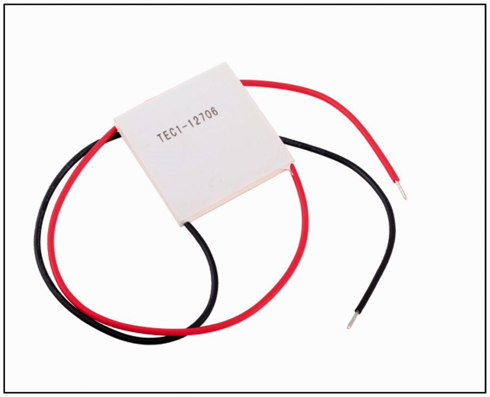

The inlet and outlets of the conduit were fitted with an anemometer for measuring the air velocity. Both the conduits were insulated to minimize any heat loss to the surroundings. The surface of TEC was applied with thermal paste to reduce the contact resistance. A K-type thermocouple is used to measure the temperature distribution. A schematic representation is shown in Figure 11.
Schematic arrangement of STEM.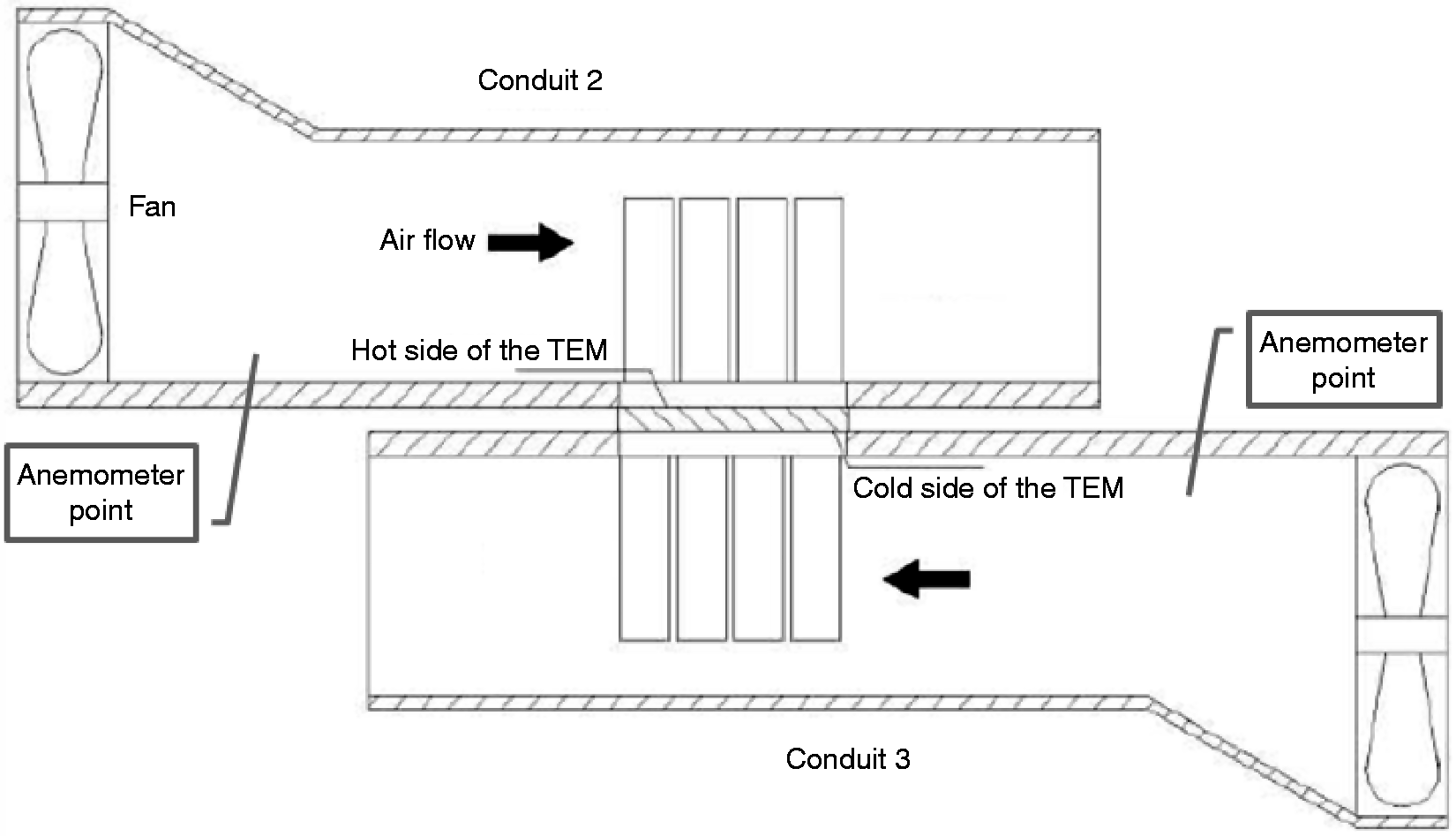
Experimental analysis
As already mentioned, the low-power fans used were the same in both the conduits. The fan speed was regulated with the help of potentiometer and corresponding air velocities were measured at five different points.
Table 3 presents the different measured values of various parameters at respective points on potentiometer.
Air velocities (m/s) at various mass flow rates (10−3 kg/s).

Parameters against TEC voltage.

RH: relative humidity; TEC: thermoelectric cooler.
For the cold conduit, the changes in dry bulb temperature along with the relative humidity for different voltages are shown in Figure 12. It is observed that due to Joule heat an increase in TEC voltage resulted with an increase in temperature at the outlet, while a decrease of 3–5℃ in air temperature was also noted.
Variation in parameters against voltage.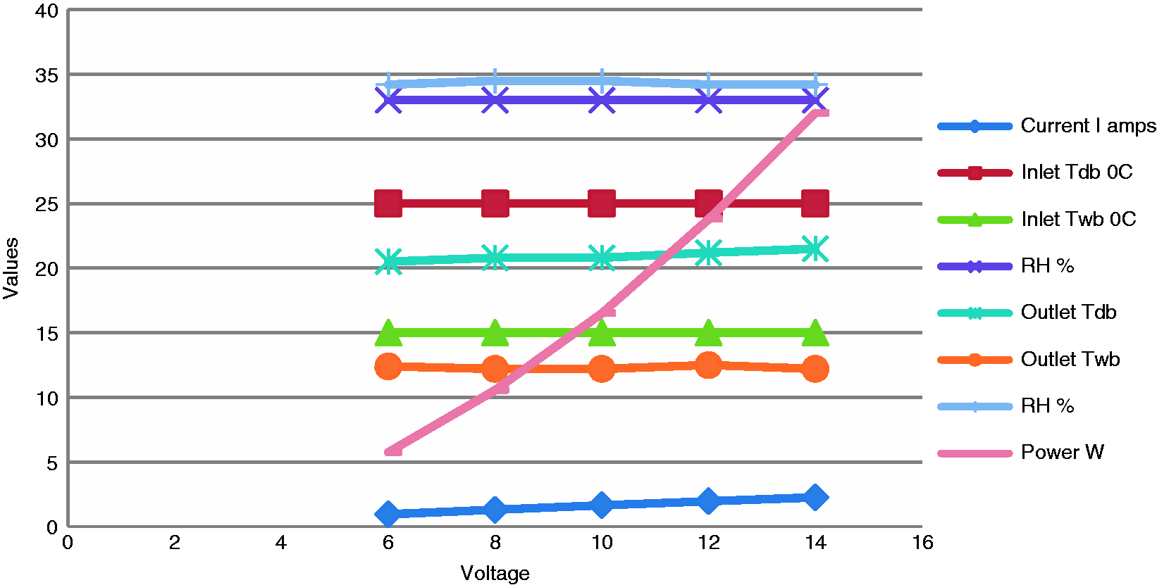
In order to evaluate the COP and the psychometric values of air for cooling and heating, 8 V were applied to the TEC. In case of the cold conduit, the negative values indicate the heat transfer from air to TEC. The resulting values are presented in Table 5. COP was calculated with the help of equations (12) and (13). Figure 13 indicates the change in COP for different fan speeds. It can be seen that COP increases with increase in fan speed for both the hot and the cold conduit. This is due to the fact that the increase in fan speed results in increased mass flow and a corresponding increase in heat transfer rate.
Fan speed vs. COP for hot and cold conduit. Psychometric values at 8 V TEC. COP: coefficient of performance; TEC: thermoelectric cooler.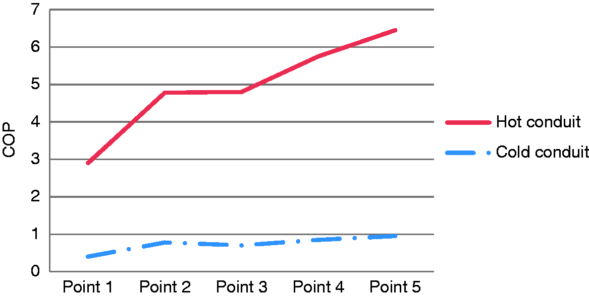

The COP for the cold and the hot conduit was measured in the range 0.5–1 and 2.6–5, respectively. For the purpose of calculations, the electricity consumption of fans was considered negligible. The derived COP values are although lower however the integration of solar energy and improvements in energy efficiency can offer better values.
Conclusion
The current study presented a new design of building wall that integrates the solar PV panel with the thermoelectric heat pump. The environmentally friendly system provides electrical power along with space heating and cooling. The construction cost of the system can be absorbed by the building cost since this PV-TEHP module replaces a part of the building such as a window or a façade, and hence is part of the building envelope. Also as the cost of solar panels is declining with improved technology along with the decrease in cost of thermoelectric materials, it will result in a universal low cost solution for the building envelope with additional savings in HVAC-related energy costs as well.
The experimental results indicated that in the heating mode, the temperature of air in the hot conduit increase by 11℃ with an application of 8 V. However, in the cooling mode, the decrease in temperature recorded was 1.5℃ with the same voltage. The results also indicated that the increase in mass flow with the increase in fan speed resulted in improved COP and heat transfer coefficient.
The study shows that TEHPs can serve as a good alternative in HVAC applications. The use of solar energy through solar panels is especially useful for space cooling in summers. Further these systems have a long life and are maintenance free and can also be used to pre-cool or pre-heat air in existing HVAC systems.
The proposed system has the potential to reduce the energy consumptions in buildings especially in the heating mode. The model is a prototype and need to be enhanced in features and material to be of practical application as a commercial product. The efficiency of the STEM system can be improved with the use of better technology both in the context of solar panels and in the TEC. For instance, multi-junction solar panels can be utilized for greater power generation and at the same time high efficiency TEC can provide with better heating and cooling effects. The deployment of efficient STEM systems can contribute to a reduction in building energy needs and hence lower consumption of fossil fuels and consequently aid in climate change mitigation.
Footnotes
Declaration of conflicting interests
The author(s) declared no potential conflicts of interest with respect to the research, authorship, and/or publication of this article.
Funding
The author(s) received no financial support for the research, authorship, and/or publication of this article.