






Abstract
Informal housing in hot climates commonly uses corrugated galvanized iron (GI) sheet roofs, which absorb intense solar radiation and rapidly transmit heat indoors, causing thermal discomfort and elevated heat-stress risk. This study evaluates a low-cost, construction-ready retrofit: a 20° pitched ventilated double-tin roof with a continuous air cavity and distributed inlet–outlet vents to enhance buoyancy-driven heat removal.
A multi-scale modelling–measurement framework integrates peak-load CFD with conjugate heat transfer and radiative effects to resolve cavity airflow, transient EnergyPlus simulations using Typical Meteorological Year (TMY) data to predict diurnal indoor response, and validation using a 1:3 scale outdoor prototype under summer conditions in Pune, India.
Results show buoyancy-dominated ventilation within the cavity (Rayleigh number ≈ 1.3 × 10⁵), forming a stable upward flow that removes absorbed heat before it reaches the indoor-facing sheet. Compared to a single-layer GI roof, the system reduces inward heat flux by 30–35% and lowers indoor operative temperature by up to 6.2°C (4–6°C average). Experiments confirm roof-surface temperature reductions of 14–17°C and enhanced indoor cooling (8–12°C) under wind-assisted conditions. An optimal cavity gap of 6–10 cm is identified.
The study provides experimentally validated design guidance for scalable, low-cost passive cooling in climate-vulnerable housing.
Practical application
This study provides construction-ready guidance for improving thermal comfort in buildings with corrugated GI roofs, commonly used in low-cost housing. The proposed ventilated double-skin roof system uses simple materials and passive airflow to reduce indoor heat gain without mechanical cooling. The identified optimal cavity gap (6–10 cm) and quantified performance improvements enable practitioners, engineers, and builders to implement an effective, low-cost retrofit strategy. The findings are directly applicable to building design and refurbishment in hot climates, particularly in resource-constrained settings where energy-efficient and affordable cooling solutions are required.
The thermal performance reported in this study corresponds to newly installed GI sheets. In practical applications, dust accumulation, surface weathering, and oxidation may gradually increase solar absorptivity over time, leading to higher outer-sheet temperatures and some reduction in cooling effectiveness. Nevertheless, the underlying buoyancy-driven ventilation mechanism remains active and may partially compensate for the increased solar heat gain through enhanced natural airflow within the cavity. Periodic cleaning or the use of reflective coatings could help maintain long-term thermal performance in dusty environments.
Keywords
Introduction
Corrugated galvanized iron (GI) sheet roofing is widely used in informal and low-income housing across South Asia, Sub-Saharan Africa, and Latin America due to its low cost, lightweight construction, and rapid assembly. However, the high solar absorptivity and low thermal resistance of thin metal sheets result in rapid transmission of absorbed heat into indoor spaces. Under peak summer conditions, indoor air temperatures in tin-roof and other lightweight dwellings can substantially exceed ambient conditions, leading to severe thermal discomfort and increased heat-stress risk. Field studies from India and investigations of vulnerable housing have highlighted the susceptibility of such buildings to overheating due to low thermal mass and limited passive cooling measures.1,2 This overheating poses growing health risks as heatwaves become more frequent and intense, compounded by limited access to mechanical cooling and urban heat-island effects in low-income settlements.3–6 Informal housing in hot climates is characterized by the widespread use of lightweight metallic roofing systems with high solar absorptivity and low thermal inertia, which leads to rapid indoor heat gain and thermal discomfort.7–9 Various passive cooling strategies, including reflective coatings, insulation layers, and ventilated roof configurations, have been investigated to mitigate roof-induced heat gains.10–14
Passive cooling strategies are therefore essential for mitigating heat exposure in such environments. Among these, ventilated air cavities (double-skin systems) are well established in building science as a means to reduce heat transfer through a combination of increased thermal resistance and buoyancy-driven ventilation. Prior studies on solar chimneys and cavity ventilation demonstrate that airflow induced by temperature gradients can significantly enhance heat removal, particularly when vent configuration and cavity geometry are optimized.15,16 Similarly, investigations on naturally ventilated double-skin façades indicate that solar incidence, opening arrangement, and cavity dimensions strongly influence thermal performance and indoor conditions.17,18 Ventilated double-skin roof systems have been shown to enhance heat removal through buoyancy-driven airflow and reduce conductive heat transfer to indoor spaces.19–23 Reviews and meta-analyses further confirm that double-skin systems can improve thermal comfort and reduce cooling loads when appropriately adapted to climate and material characteristics. 24
Despite this established foundation, the applicability of such systems to informal tin-roof housing remains limited. Much of the existing literature focuses on insulated envelopes, mechanically ventilated façades, or high-performance building systems that are not directly transferable to low-cost, thin-sheet metal constructions.25–27 In informal settlements, roofs are typically uninsulated, highly conductive, and constructed with minimal detailing, resulting in distinct thermal and airflow behavior compared to conventional buildings. Alternative passive approaches, including phase-change materials, advanced composites, or green roofs, often introduce cost, weight, or maintenance constraints that restrict their adoption in resource-constrained contexts.6,28–30 While cool-roof coatings can reduce solar heat gains, they do not provide ventilation-driven heat removal within a roof cavity, limiting their effectiveness under high solar loads. 31
A key research gap therefore exists: a construction-ready, low-cost ventilated roof configuration specifically optimized for corrugated tin-sheet housing has not been systematically evaluated, particularly with respect to the influence of cavity geometry, vent arrangement, and roof inclination under realistic climatic conditions. However, most existing studies focus on conventional building envelopes or insulated roof systems, with limited attention to thin corrugated metal roofs commonly used in informal housing.32–34 The thermo-physical behaviour of thin GI sheets, including low thermal mass and strong radiative coupling, differs significantly from masonry or insulated roofs, influencing heat-transfer pathways and ventilation performance.35,36 Unlike conventional building envelopes, thin corrugated GI roofs exhibit negligible thermal mass, strong radiative coupling between inner and outer surfaces, and construction constraints that limit cavity depth and detailing. These characteristics fundamentally alter the flow regime and heat-transfer pathways compared to insulated or masonry roof systems, necessitating a dedicated investigation. While ventilated cavity principles are well-established, their application to thin, uninsulated corrugated GI sheets—where the cavity is bounded by two highly conductive, low-thermal-mass surfaces with strong radiative coupling—has not been systematically quantified under realistic solar loading and validated against outdoor measurements.
To address this gap, the present study proposes and evaluates a ventilated double-tin roof system designed for low-cost deployment. The methodology combines (i) computational fluid dynamics (CFD) to resolve buoyancy-driven cavity airflow and heat-transfer mechanisms under peak solar loading, (ii) transient EnergyPlus simulations using Typical Meteorological Year (TMY) weather data to quantify diurnal indoor thermal response, and (iii) outdoor prototype experiments to validate performance under real environmental conditions. The coupling between CFD and EnergyPlus is implemented by deriving ventilation characteristics from CFD analysis and incorporating them into building-scale simulations.
The primary contributions of this work are threefold. First, it establishes a validated multi-scale modelling framework linking cavity-scale thermo-fluid behavior with whole-building thermal response for informal housing applications. Second, it provides quantitative performance metrics, including heat-flux reduction and indoor temperature reduction, supported by both simulation and experimental validation. Third, it identifies a practical design optimum for cavity gap width (6–10 cm) and highlights the role of wind–buoyancy interaction in enhancing cooling performance under real conditions.
Overall, this study advances passive cooling strategies for climate-vulnerable housing by delivering experimentally validated, design-oriented guidance for a scalable and low-cost ventilated GI roof system.
Methodology
Overall research framework and climate inputs
This study employs an integrated computational–experimental workflow to quantify the passive cooling performance of a corrugated double-tin ventilated roof installed on a representative low-cost single-room shelter. The workflow (Figure 1(a)) distinguishes between two complementary modelling approaches: (i) steady peak-load CFD snapshots that resolve cavity-scale thermo-fluid mechanisms, and (ii) transient EnergyPlus simulations using Typical Meteorological Year (TMY) weather data to capture diurnal building response. Outdoor prototype measurements provide validation under real environmental conditions.24,37 Step 1: Problem definition and climate data. The target application is heat-vulnerable tin-sheet housing in hot climates, where lightweight metal-roofed dwellings are especially prone to indoor overheating, thermal discomfort, and elevated heat-stress risk during summer conditions.1,2 Two climate datasets are used: (i) on-site measured data during the prototype validation day (ambient temperature and global solar irradiance), and (ii) the Pune TMY weather file (IND_MH_Pune.AP.430630_TMYx.2004–2018.epw) for whole-day building-scale prediction in EnergyPlus. The measured diurnal profiles are presented in Figure 1(b), while the representative TMY diurnal profiles are shown in Figure 1(c). Figure 1(c) is intended to illustrate representative daytime trends derived from the TMY dataset and should not be interpreted as the original hourly weather-file data. Step 2: Geometry and parametric definition. A single-room shelter geometry (3 m × 3 m × 2.5 m) is adopted with a 20° inclined corrugated double-tin roof comprising two sheets separated by a ventilated cavity. Key design parameters (air-gap width, vent arrangement, and inner-surface radiative properties) are defined for subsequent analysis, with the baseline configuration corresponding to the practically buildable prototype.
38
Step 3: CFD peak-load snapshots (steady-state). CFD resolves the coupled thermo-fluid mechanisms in and around the ventilated cavity: buoyancy-driven flow development, radiative exchange between sheets, and conjugate conduction through the tin layers. CFD cases are solved at selected peak-load instants identified from the measured outdoor test day (Figure 1(b), shaded region). For each snapshot, the corresponding ambient temperature and incident solar loading on the 20° roof plane are applied (Section 2.3.1). This peak-load strategy targets the conditions that control maximum indoor overheating risk.16,30 The modelling approach follows established practices in conjugate heat transfer and radiative heat exchange for building envelope analysis.20,21 Step 4: EnergyPlus transient simulation (diurnal/seasonal). Whole-room thermal response is predicted using TMY weather files, which provide hourly ambient temperature, solar radiation components, wind conditions, and sky information. Unlike steady CFD snapshots, EnergyPlus captures the full diurnal evolution of indoor air temperature under realistic time-varying forcing (Figure 1(c)). CFD outputs (surface temperatures and heat flux characteristics) inform the roof heat-transfer behaviour in EnergyPlus, but the two simulations are performed sequentially rather than as a coupled co-simulation.24,37 Whole-building energy simulation using EnergyPlus has been widely applied for evaluating passive cooling strategies under varying climatic conditions.22,23 Step 5: Pilot prototype validation (outdoor exposure). A 1:3 scale prototype is tested under outdoor summer conditions to validate the cooling predicted by the modelling framework. The measured ambient temperature and solar irradiance (Figure 1(b)) enable direct traceability between experimental boundary forcing, CFD peak-load snapshots, and EnergyPlus transient simulations.37,38 (a) Methodological workflow of the study. (b) Climate forcing during on-site prototype validation. (c) Typical meteorological year (TMY) climate forcing used in EnergyPlus.

Roof configuration, geometry, and parameters varied
The investigated roof is a corrugated double-tin ventilated assembly mounted at 20° inclination, representative of common tin-roof practice in informal housing. The roof comprises two thin galvanized iron (GI) sheets separated by a ventilated air cavity (baseline 6 cm, varied parametrically), designed to reduce heat transfer to the indoor space through: (i) reduced conduction across the assembly, (ii) buoyancy-driven ventilation within the cavity, and (iii) reduced radiative gains via surface optical properties.16,38
Base construction (reference case): • Outer corrugated GI sheet (weather side): reflective/galvanized corrugated tin sheet exposed to solar loading and outdoor convection/radiation. Solar absorptivity α and long-wave emissivity ε are applied consistently across CFD and EnergyPlus.18,38 • Inner corrugated/bare GI sheet (room side): sheet facing the indoor zone; its emissivity is varied in parametric cases to test the effect of low-ε versus high-ε inner surfaces on radiative exchange and net heat transfer.17,18 • Ventilated cavity: a continuous air gap between the sheets. Ambient air enters through a lower vent row and exits through an upper vent row due to buoyancy-driven draft as the cavity air warms.16,38
Figure 2 shows the parametric geometry, assembly layers, and ventilation path, including the outer corrugated sheet, cavity spacers, inner sheet, and vent rows with buoyancy-driven flow. These geometric and parametric variables are referenced in the CFD boundary conditions, mesh refinement, and experimental replication.16,38 Geometry of the ventilated double-tin roof system. The prototype consists of a 3 m × 3 m × 2.5 m room covered by a 20° pitched double-layer corrugated GI roof. The ventilated cavity gap (H = 1, 3, 6, 10, or 12 cm) is formed between the outer reflective sheet and inner bare-metal sheet. Outdoor air enters the cavity through continuous lower inlet vents located along the eaves and exits through continuous upper outlet vents located near the roof ridge, establishing buoyancy-driven ventilation within the roof cavity.
CFD modelling
Computational domain and boundary conditions
The computational domain represents the thermo-fluid behaviour of the 20° inclined double-tin ventilated roof under buoyancy-driven natural convection. The model includes the outer reflective tin sheet, the inner bare-metal tin sheet, the ventilated air cavity, and an extended surrounding ambient-air region to minimize boundary confinement effects at the ventilation openings. Both tin sheets are explicitly modelled as solid regions to enable conjugate heat transfer, while the cavity and external regions are treated as fluid domains.37,38
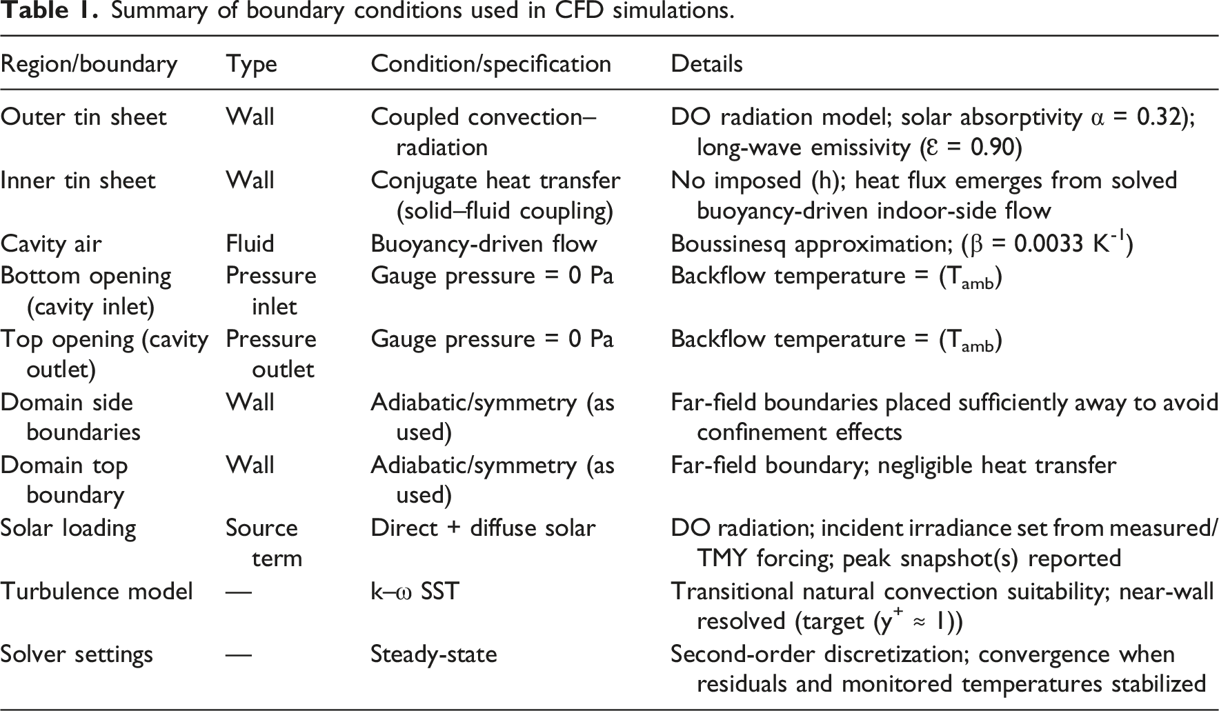
Radiative heat transfer is incorporated using the Discrete Ordinates (DO) model to resolve solar absorption, long-wave emission, and radiative exchange within the cavity.18,38 The outer tin sheet is assigned solar absorptivity α = 0.32 and long-wave emissivity ε = 0.90, while the inner tin sheet is assigned ε = 0.84. Incident solar loading is applied as a directional radiative heat flux corresponding to peak summer conditions in Pune, India (18.5204° N, 73.8567° E), with values of 850–900 W/m2 imposed at the roof inclination. 18
Ventilation within the cavity is driven purely by buoyancy forces. To avoid prescribing an artificial inlet velocity, the lower opening is specified as a pressure inlet (0 Pa gauge), allowing ambient air to enter naturally; the backflow temperature is set to the measured ambient value (T = Tamb). The upper opening is specified as a pressure outlet (0 Pa gauge), permitting free discharge of heated air. This pressure-based formulation ensures that the mass flow rate is determined by density differences generated within the heated cavity, consistent with buoyancy-driven ventilation modelling practice.15,16 The opening geometry follows the experimental prototype configuration.
All solid surfaces are assigned no-slip boundary conditions. Far-field boundaries of the extended ambient domain are placed sufficiently distant from the roof (at least five characteristic lengths from the ventilation openings) and treated as zero heat-flux (adiabatic) boundaries to avoid parasitic heat gains and spurious recirculation. 38 Buoyancy is modelled using the Boussinesq approximation, which is suitable for natural-convection dominated flows with moderate temperature differences.37,38 Steady-state CFD is performed for representative peak-load snapshots identified from the measured diurnal forcing.
Figure 3 presents a schematic of the computational domain and applied boundary conditions. Table 1 provides a complete summary of boundary-condition specifications. CFD model domain and boundary conditions showing pressure inlet, pressure outlet, buoyancy-driven cavity airflow, and coupled heat-transfer interactions within the ventilated double-skin roof system. Summary of boundary conditions used in CFD simulations.
Numerical schemes and solver settings
The governing equations for mass, momentum, and energy conservation are solved using the finite-volume method in ANSYS Fluent. Turbulence is modelled using the k–ω SST formulation, which provides robust performance for mixed laminar–transitional natural convection and improved near-wall accuracy compared to standard k–ε models. 37 This choice is particularly suitable for narrow ventilated cavities where buoyancy-driven flow may transition locally between laminar and weakly turbulent regimes. 38
Pressure–velocity coupling is achieved using the SIMPLEC algorithm. Second-order upwind discretization schemes are employed for momentum, energy, and turbulence transport equations to minimize numerical diffusion. 37 Radiative transfer is solved using the DO model with angular discretization adequate to capture directional solar loading and surface-to-surface radiation within the cavity.18,38
All simulations are performed under steady-state conditions, representing peak thermal loading scenarios during summer afternoons. Transient variations in ambient temperature and solar irradiance are handled separately through EnergyPlus simulations. The steady-state CFD approach enables detailed examination of dominant heat-transfer mechanisms at maximum thermal stress.16,38
Convergence is assumed when normalized residuals for continuity, momentum, turbulence, and energy equations drop below 10−6. Key solution monitors (inner-sheet temperature, cavity air temperature, and outlet mass flow rate) are tracked to ensure solution stability. 37
Mesh generation and grid-independence verification
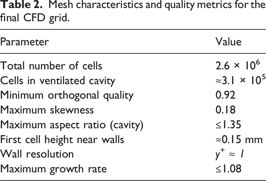
A structured multi-block mesh is generated to resolve buoyancy-driven airflow and coupled heat transfer within the ventilated double-tin roof assembly. Particular attention is given to near-wall thermal gradients, natural-convection boundary layers, and flow development at the ventilation openings.37,38 The computational grid uses quadrilateral elements throughout to ensure numerical stability.
As shown in Figure 4(a), the full computational domain includes the inclined roof geometry and an extended ambient region to avoid artificial confinement effects.
38
Local mesh refinement is applied at the bottom ventilation opening (Figure 4(b)) to capture buoyancy-induced inflow.
16
The ventilated air cavity between the outer and inner sheets is discretized using a high-resolution structured mesh (Figure 4(c)), enabling accurate prediction of temperature stratification within the 6 cm cavity.
38
Structured computational grid used for CFD simulations: (a) full computational domain including inclined roof and surrounding ambient region; (b) local mesh refinement at the bottom ventilation inlet to resolve buoyancy-driven inflow; (c) high-resolution structured mesh within the 6 cm ventilated cavity between the outer and inner tin sheets; (d) near-wall boundary-layer mesh along tin surfaces showing inflation layers with y
+
≈ 1 for low-Reynolds-number turbulence modelling.
Near-wall inflation layers are applied along both tin-sheet surfaces (Figure 4(d)). The first cell height is selected to maintain y+ ≈ 1, ensuring full resolution of viscous and thermal sublayers without wall functions. This approach is consistent with the low-Reynolds-number formulation of the k–ω SST turbulence model. 37
A grid-independence study is conducted using three mesh densities: coarse (1.2 × 10⁶ cells), medium (2.0 × 10⁶ cells), and fine (2.6 × 10⁶ cells). Key monitored quantities (inner-sheet temperature and cavity outlet air temperature) show differences of less than 0.3% between the medium and fine meshes. The fine mesh is selected for all subsequent simulations. 37
Transient building-scale simulation (EnergyPlus) and coupling logic
EnergyPlus computes diurnal indoor temperature for a 3 m × 3 m × 2.5 m single-zone room under real weather forcing. EnergyPlus simulations were performed using the Pune Typical Meteorological Year weather file (IND_MH_Pune.AP.430630_TMYx.2004–2018.epw), representing long-term climatic conditions at Pune Airport, India. The TMY dataset was used to assess representative whole-day building thermal performance under typical summer conditions, whereas measured ambient temperature and solar irradiance from the experimental campaign were used in the CFD simulations and prototype validation. TMY weather files provide hourly ambient temperature, solar radiation, wind speed, and sky conditions. The roof construction is represented as a double-layer assembly with a ventilated air cavity.
The coupling between CFD and EnergyPlus is sequential, not a dynamic co-simulation. CFD results are used to inform the EnergyPlus model in the following ways: • Effective heat flux reduction trends under peak conditions • Cavity ventilation rates (expressed as air changes per hour, ACH-equivalent) derived from CFD velocity fields • Sensitivity of thermal performance to gap size and vent configuration
The ventilation characteristics incorporated into EnergyPlus were derived from steady-state CFD simulations performed under representative peak summer conditions and were implemented as fixed ACH-equivalent buoyancy-driven ventilation rates throughout the simulation period. Although the TMY weather file contains hourly wind-speed data, dynamic wind-pressure coupling within the roof cavity was not modelled, and the ventilation rates were therefore not adjusted in response to changing wind conditions. Consequently, the EnergyPlus simulations represent a buoyancy-dominated baseline performance of the ventilated roof system, while the outdoor experiments additionally captured wind-assisted ventilation effects. This separation of roles is explicitly maintained: CFD resolves mechanism-level physics under peak thermal loading, whereas EnergyPlus captures the time-varying indoor thermal response under representative climatic conditions using TMY weather data.24,37 A limitation of this sequential coupling approach is that cavity ventilation rates derived under peak thermal loading may overestimate buoyancy-driven airflow during periods of weaker solar heating, such as early morning and late afternoon, when temperature differences across the cavity are smaller. However, because the primary objective of the study was to evaluate performance under peak overheating conditions, this simplification is not expected to significantly affect the principal conclusions regarding roof effectiveness. Future work may employ transient CFD–building co-simulation frameworks that allow cavity ventilation rates to vary dynamically with changing thermal and meteorological conditions throughout the day.
Pilot prototype construction (validation setup)
A 1:3 scale prototype is constructed to validate the roof concept under outdoor summer exposure in Pune, India (18.5204° N, 73.8567° E). The prototype replicates:
A conventional single-layer corrugated tin prototype is first constructed as a baseline to quantify overheating under typical GI roofing (Figure 5). The enclosure consists of a single GI sheet envelope mounted on a wooden support frame, with plan dimensions 1.0 m × 1.44 m × 1.0 m. Field-based validation is essential to capture real-world thermal behaviour and environmental variability, particularly in naturally ventilated systems.32,33 Baseline single-layer corrugated GI hut (1.0 m × 1.44 m × 1.0 m) used for experimental comparison. The enclosure consists of a single GI sheet envelope mounted on a wooden support frame.
A second prototype incorporating the double-tin ventilated roof is then fabricated with the same plan dimensions and comparable wall construction, so that differences in indoor temperature can be attributed primarily to the roof assembly (Figure 6). Double-tin ventilated-roof prototype (1:3 scale) used for validation under outdoor summer exposure in Pune, India. The roof comprises two GI sheets separated by a ventilated cavity with inlet and outlet vent rows to enable buoyancy-driven airflow; temperature instrumentation is mounted for continuous monitoring.
The roof cavity gap is maintained using non-conductive spacers, and vent openings are provided to permit buoyancy-driven airflow through the cavity.16,38 The baseline and ventilated-roof prototypes employed identical wall materials, dimensions, and instrumentation. The only difference between the two configurations was the roof assembly, thereby isolating the thermal impact of the ventilated double-layer roof.
Scale effects and similarity criteria
The 1:3 scale prototype was designed to reproduce the dominant thermal and airflow mechanisms of the proposed ventilated roof system rather than achieve exact dynamic similarity with a full-scale installation. For buoyancy-driven natural convection, the governing dimensionless parameter is the Rayleigh number (Ra), which scales approximately with the cube of the characteristic length (Ra ∝ L3).
Under representative peak summer conditions, the prototype operated at a Rayleigh number of approximately Ra ≈ 1.3 × 10⁵, corresponding to buoyancy-dominated flow with stable thermal stratification within the ventilated cavity. For a full-scale 3 m × 3 m shelter, the characteristic length increases by a factor of three, yielding an estimated Rayleigh number of approximately Ra ≈ 3.5 × 10⁶. This increase is expected to promote stronger buoyancy-induced circulation and increased flow instability, with a tendency toward a more transitional natural-convection regime.
However, the fundamental cooling mechanism remains unchanged. In both cases, heat removal is governed primarily by buoyancy-driven ventilation within the roof cavity, which transports heat from the heated outer sheet toward the upper outlet vents before it is transmitted to the indoor space. Consequently, the prototype was used primarily to validate the underlying physical mechanisms, including thermal stratification, airflow direction, and reduction of heat transfer through the ventilated roof assembly, rather than to establish a direct scaling law for full-scale performance.
Full-scale thermal performance predictions were obtained from the CFD and EnergyPlus models, which were formulated using full-scale geometry. The prototype measurements therefore serve as experimental validation of the predicted thermal behaviour, while the numerical models provide the basis for full-scale performance assessment. Since stronger buoyancy-driven airflow is expected at larger scales, the prototype results may be regarded as conservative estimates of the cooling performance achievable in practical full-scale applications.
Prototype geometry and instrumentation
The 1:3 scale experimental prototype consists of a single-room enclosure with a double-layer ventilated roof only, while walls remain single-layer GI sheets to isolate roof-driven thermal effects.
1
The roof assembly comprises an outer reflective GI sheet and an inner bare-metal GI sheet separated by a 6 cm ventilated air cavity, maintained using non-conductive spacers. The outdoor prototype was instrumented with surface-mounted temperature sensors and a data acquisition system for real-time thermal monitoring during peak solar exposure (Figure 7). Close-up of the prototype roof showing surface-mounted temperature sensors, wiring, and data-logging connections used for real-time thermal monitoring during peak solar exposure.
Ambient air enters the cavity through a continuous lower vent slot (40 mm height) along the full roof width and exits through a continuous upper vent slot (40 mm height), enabling buoyancy-driven natural convection.16,38 Figure 8 presents a schematic of the prototype geometry, vent openings, cavity height, and instrumentation layout. Schematic of the 1:3 scale experimental prototype used for validation of the double-skin ventilated roof (roof only; walls are single-layer GI).
Temperature sensors are positioned as follows (Figure 8): • • •
A miniature hot-wire anemometer is positioned at mid-cavity height to capture buoyancy-induced airflow velocity. All sensors are connected to a multi-channel data logger with synchronized time-stamping, and data are recorded at 1-min intervals during the test period.16,37,38 Surface temperature sensors are attached using thermal paste to reduce contact resistance.
In Figure 8, the roof consists of an outer reflective corrugated GI sheet and an inner bare-metal GI sheet separated by a ventilated air cavity (6 cm baseline). Ambient air enters through a continuous lower vent row (40 mm slot) and exits through a continuous upper vent row (40 mm slot) by buoyancy-driven natural convection. Temperature sensors are positioned on the inner roof surface (T1), within the indoor air volume (T2), and in the ambient environment (T3). A miniature air-velocity probe is located within the cavity to measure buoyancy-induced airflow. All sensors are connected to a multi-channel data logger for synchronized acquisition.
Note: Dimensions shown are full-scale equivalents; actual prototype is 1:3 scale (1.0 m × 1.44 m × 1.0 m).
Measurement uncertainty
Instrumentation uncertainty is quantified using manufacturer-specified sensor accuracies. Temperature sensors have an accuracy of ±0.5°C (calibrated prior to testing). Solar irradiance measurements have an accuracy of ±5%. Airflow measurements are subject to ±5–8% uncertainty depending on flow regime. Combined uncertainty in derived quantities (e.g., temperature reduction, cavity temperature difference) is estimated using root-sum-square propagation of independent sensor errors. The overall measurement uncertainty was estimated following ASHRAE Guideline 2, incorporating sensor accuracy, calibration error, and environmental variability.
Theoretical basis and governing equations
Heat transfer through the inclined double-tin ventilated roof is governed by the coupled interaction of conduction through the metal sheets, buoyancy-driven natural convection within the air cavity, and radiative exchange between cavity surfaces.16,38
Conduction through tin sheets
Heat conduction through the tin sheets is described by Fourier’s law: •

Buoyancy-driven natural convection in the cavity
Natural convection within the ventilated air cavity is driven by density differences arising from heating of the air adjacent to the outer tin sheet. The buoyancy strength is characterized by the Grashof (Gr) and Rayleigh (Ra) numbers:

For the baseline 6 cm cavity under peak summer conditions, the characteristic Rayleigh number is approximately:
This value places the flow in the laminar to transitional natural-convection regime, consistent with studies of narrow ventilated cavities in building envelopes. 38
Convective heat transfer and Nusselt number
The convective enhancement of heat transfer relative to pure conduction is quantified by the Nusselt number (Nu). For buoyancy-driven convection between parallel inclined plates, the Churchill–Chu correlation is
16
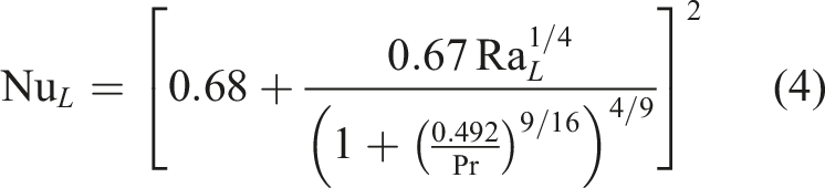
Substituting Ra ≈ 1.3 × 10⁵ and Pr = 0.71 yields Nu ≈ 10.3–10.5, indicating that convective heat transfer is an order of magnitude stronger than pure conduction across a stagnant air layer.
This correlation is used only for order-of-magnitude interpretation. Local heat-transfer coefficients are not prescribed using empirical correlations. Instead, convection is resolved directly through CFD by solving the coupled momentum and energy equations under buoyancy forces.16,38
Radiative heat exchange in the cavity
Radiative heat transfer between the inner and outer tin sheets is modelled assuming gray, diffuse surfaces. The net radiative heat flux is: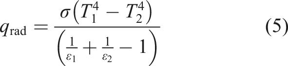
Solar heat gain
The absorbed solar heat flux on the outer tin surface is:
Combined heat-transfer mechanism
The total heat transfer through the ventilated roof is governed by the combined effects of conduction, convection, and radiation. These modes act in parallel and cannot be represented by a single equivalent thermal resistance. Instead, the ventilated cavity functions as a dynamic thermal buffer, where buoyancy-driven airflow continuously removes heat before it is transmitted to the indoor space.16,38.
Model validation strategy
Validation is carried out in two tiers: (1) (2)
Scale effects are acknowledged explicitly: geometric similarity does not guarantee dynamic similarity for natural convection because Gr, Ra, and Re scale with characteristic length. This is discussed as part of the validation interpretation rather than ignored.16,38
Model validation and uncertainty analysis
Validation is carried out in two tiers: (i) internal numerical verification (grid independence, solution stability, mass flow consistency), and (ii) experimental validation comparing CFD predictions with prototype measurements for outer sheet temperature, inner sheet temperature, indoor air temperature, and cavity airflow velocity.
Model validation is performed by comparing CFD-predicted quantities with measurements from the outdoor prototype under peak summer conditions. Due to the pilot-scale nature of the experiment, validation focuses on peak values and measured ranges rather than continuous time-series statistics.
Validation uncertainty and CFD–experiment agreement.

Using the validation quantities reported in Table 3, CFD predictions are compared against experimental measurements. For parameters reported as ranges, mid-point values are used to compute aggregate agreement metrics. The comparison yields MAE = 1.56°C, RMSE = 2.10°C, and R2 = 0.988, indicating strong overall agreement for peak-condition thermal performance evaluation.
Given that all key CFD-predicted values fall within or near experimental uncertainty bounds, the model is considered validated for evaluating the ventilated roof’s thermal performance under peak summer conditions.
Because prototype tests are conducted outdoors, wind-enhanced convection can increase measured cooling relative to steady CFD peak-load snapshots (which assume zero wind). Therefore, validation is interpreted primarily in terms of capturing correct trends, peak behavior, and the dominant buoyancy-driven mechanism rather than exact one-to-one quantitative agreement.
Assumptions and limitations
Key assumptions are stated transparently: (1) (2) (3) (4) (5) (6) The present study assumes constant thermo-radiative properties for galvanized iron sheets and does not explicitly model the effects of ageing, dust accumulation, or oxidation. Changes in surface absorptivity over time may alter roof temperatures and cooling performance. Future work should investigate long-term field performance and quantify the sensitivity of the proposed roof system to surface weathering under different climatic conditions. (7) A limitation of the present sequential coupling approach is that wind-induced variations in cavity ventilation were not dynamically coupled to the EnergyPlus model; consequently, the simulated results primarily represent buoyancy-driven performance and may underestimate cooling benefits under favourable wind conditions.
Results and discussion
The passive cooling performance of the 20° inclined corrugated double-tin ventilated roof was evaluated using a hybrid workflow combining steady CFD peak-load snapshots, transient EnergyPlus simulations, and outdoor prototype measurements. The measured diurnal ambient temperature and solar irradiance used to define representative peak CFD snapshots are shown in Figure 1(b), while the corresponding TMY diurnal profiles employed in EnergyPlus are shown in Figure 1(c). This separation of roles—CFD for resolving local thermo-fluid mechanisms at critical peak conditions and EnergyPlus for capturing time-varying indoor response—is consistent with established practice in ventilated envelope studies24,27,37,38
Cavity thermal field and vertical stratification (CFD)
The CFD-predicted temperature contours reveal strong vertical stratification within the ventilated cavity under peak solar loading (Figure 9(a)). The temperature field is shown at the mid-span cross-section along the roof length (from lower inlet to upper outlet). Air entering from the lower vent row is progressively heated along the inclined cavity and exits through the upper vent, producing a layered thermal structure. Peak temperatures (55–57°C) are concentrated near the underside of the outer reflective sheet, whereas the air adjacent to the inner sheet remains significantly cooler (37–38°C). This confirms that the ventilated cavity acts as a thermal buffer, relocating the highest temperatures away from the indoor boundary and reducing inward conductive heat transfer. (a) Temperature contours (°C) showing the formation of a hot buoyant plume adjacent to the underside of the outer reflective tin sheet and a comparatively cooler region near the inner sheet. (b) Velocity magnitude (m s−1) and streamlines illustrating buoyancy-driven upward airflow and continuous heat removal through the cavity Peak-load CFD results for the 6 cm gap case at mid-span cross-section (along roof length from inlet to outlet): (a) cavity temperature field (°C) with colour bar showing temperature range from 35°C (coolest, dark blue) to 60°C (hottest, dark red); (b) velocity magnitude field (m/s) with streamlines showing flow direction.

The hot buoyant plume (red/orange region in a) forms adjacent to the underside of the outer reflective tin sheet, while a cooler region (blue/green) persists near the inner sheet. Velocity streamlines in (b) illustrate a coherent upward draft from the lower inlet to the upper outlet, with no recirculation zones.
Such stratified behaviour is characteristic of buoyancy-driven ventilation in roof and façade cavities and has been widely reported in ventilated roof and double-skin façade studies under summer conditions.18,24,37,38 Compared with shallow or flat roofs, the 20° inclination promotes a continuous upward convection pathway, limiting stagnation near the outlet and improving heat evacuation efficiency.16,38
Buoyancy-driven airflow patterns and ventilation effectiveness (CFD)
The velocity field (Figure 9(b)) demonstrates a coherent buoyancy-driven upward draft throughout the cavity height. Flow accelerates from approximately 0.10 m/s at the inlet to 0.24 m/s near the outlet as air is heated and expands, with no significant recirculation zones observed. This behaviour indicates that the selected cavity gap and vent configuration enable effective natural ventilation rather than short-circuiting.
The computed Rayleigh number for the baseline 6 cm cavity is approximately 1.3 × 10⁵, placing the flow firmly in the laminar-to-transitional natural-convection regime. Similar flow magnitudes and patterns have been reported for naturally ventilated double-skin façades and solar-chimney-assisted systems operating under strong solar forcing.15,16,27,37 The pressure-based inlet/outlet formulation allows the mass flow rate to emerge naturally from buoyancy forces, enhancing the physical realism of the CFD predictions. 16
Inner-surface temperature reduction and heat-flux suppression
A key performance metric is the reduction in inner roof sheet temperature, which directly governs heat transfer to the indoor space. Under peak conditions, the temperature difference between the outer and inner sheets exceeds approximately 15°C, with the inner sheet stabilizing around 37–38°C in CFD. This reduction arises from the combined effects of radiative shielding by the outer sheet and convective heat removal within the ventilated cavity.
Relative to a conventional single-layer tin roof, the ventilated double-sheet configuration reduces inward heat flux by approximately 30%–35%, consistent with values reported for ventilated roof and façade systems in hot climates.37,38 Unlike advanced material-based approaches (e.g., PCM or adaptive façades), this reduction is achieved using simple geometry and passive ventilation, supporting applicability in low-income housing contexts.1,31
Diurnal indoor response under TMY forcing (EnergyPlus)
EnergyPlus simulations using TMY weather data (Figure 1(c)) show that the ventilated roof consistently lowers indoor operative temperature throughout the day. The model predicts an average daytime reduction of 4–6°C, with a peak reduction of approximately 6.2°C during the hottest hours (13:00–14:00 local time). The ventilated roof also delays the timing of peak indoor temperature by approximately 30 min relative to the single-layer baseline, indicating a reduction in heat-gain rate.
These reductions are particularly meaningful for informal housing, where indoor overheating frequently exceeds comfort and health thresholds.1,3,31 Prior studies have similarly highlighted the effectiveness of passive envelope strategies in reducing indoor heat stress under hot-climate conditions.6,22,23
Experimental validation against CFD predictions
Prototype measurements confirm the feasibility of the ventilated roof under real outdoor exposure in Pune, India. The measured outer sheet temperature reached approximately 53–54°C, closely matching the CFD peak-load prediction of 55–57°C given sensor uncertainty and wind variability. Inner-sheet temperatures (36–38°C) and cavity temperature gradients (14–17°C) also show strong agreement.
Validation summary comparing CFD peak-load predictions with 1:3-scale prototype measurements.
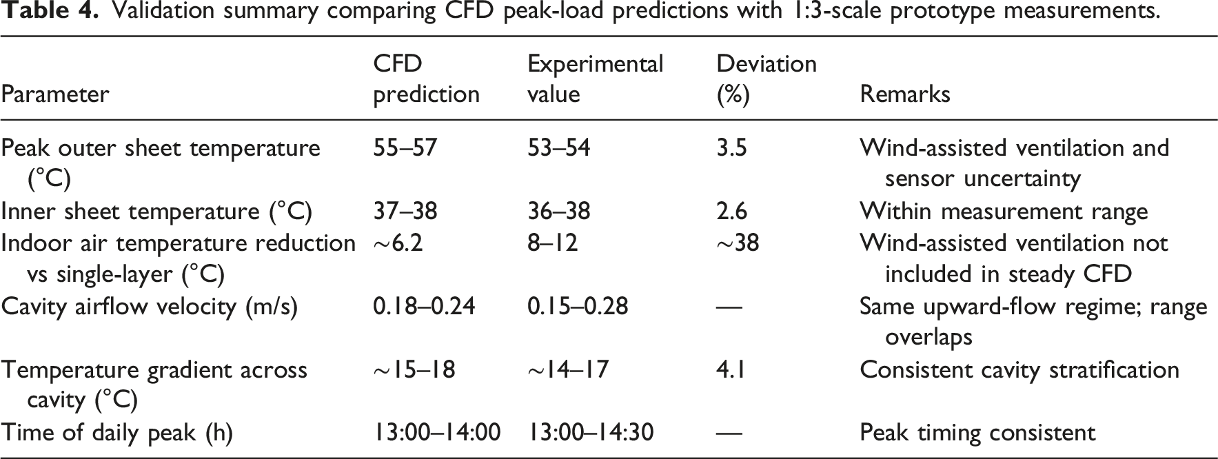
The experimentally observed indoor air temperature reduction (8–12°C) exceeds the EnergyPlus-predicted peak reduction of 6.2°C. This difference is attributed to intermittent ambient breezes (wind speeds of 0.5–2.0 m/s during testing), which enhance cavity air renewal beyond purely buoyancy-driven flow. Wind–buoyancy coupling effects are well documented in solar chimney and naturally ventilated cavity studies15,16 and explain the stronger cooling observed in the field. The discrepancy between simulated and measured indoor temperature reductions is therefore attributed primarily to wind–buoyancy interaction. While CFD and EnergyPlus represented buoyancy-driven ventilation only, the outdoor prototype experienced intermittent ambient breezes that enhanced cavity air renewal and convective heat removal.
As shown in Table 4, the agreement is strongest for inner-sheet temperature and cavity temperature gradient, where buoyancy is the dominant driver. The larger deviation in indoor air temperature reduction reflects the additional wind-assisted ventilation present in the outdoor test but not represented in the steady, no-wind CFD snapshots.15,16 Given that all key CFD-predicted values fall within or near experimental uncertainty bounds, the model is considered validated for evaluating the ventilated roof’s thermal performance under peak summer conditions. The larger experimental cooling (8–12°C) relative to the simulated cooling (6.2°C) indicates that wind-assisted ventilation provides additional heat removal beyond the conservative buoyancy-only baseline represented in the CFD and EnergyPlus models.
Gap-width sensitivity and identification of an optimal range
The influence of cavity gap width on inner roof surface temperature is summarized in Figure 10. Increasing the gap width from 2 cm to 6 cm improves thermal performance by strengthening buoyancy-driven ventilation. However, beyond an optimal range (approximately 6–10 cm), further increases lead to a progressive rise in inner-surface temperature. Effect of ventilated cavity gap width on inner roof surface temperature under peak summer conditions.
The minimum inner-surface temperature (36.8°C) occurs at 10 cm gap. The curve shows decreasing temperature from 2 cm to 10 cm, then increasing gradually at 12 cm and 14 cm.
Explanation of the trend
The observed non-monotonic behaviour arises from two competing mechanisms: • • •
This trend has been reported in parametric studies of ventilated roofs and double-skin façades, where optimal cavity depths typically range between 5 cm and 15 cm depending on inclination and heating conditions.17,24,38
Practical implications
Among the tested configurations, the minimum inner-surface temperature is observed at 10 cm. However, the incremental improvement from 6 cm to 10 cm is comparatively small (approximately 1.2°C reduction). Therefore, 6–10 cm is identified as the practical optimum range, balancing thermal performance with low-cost constructability and on-site implementation constraints in informal GI-sheet housing (where larger gaps require additional framing material and spacers). This optimum range is consistent with the observed cavity temperature stratification and the predicted buoyancy-dominated flow regime under peak solar loading.
Comparison with prior studies and novelty of the present work
The combined CFD, EnergyPlus, and experimental evidence indicates that a ventilated double-tin roof can deliver substantial indoor temperature reductions without mechanical energy input. The measured reductions compare favourably with other passive cooling strategies, including cool roofs (typical reductions of 3–5°C) and PCM-based systems (5–8°C), while relying only on widely available materials.13,29,31,39 Given the documented vulnerability of informal settlements to heat stress,31,33,34 the proposed roof offers a scalable, low-cost adaptation strategy aligned with current climate-resilience priorities.6,40 Similar reductions in roof heat flux and indoor temperature have been reported in studies on ventilated roofing and passive cooling interventions.34–36
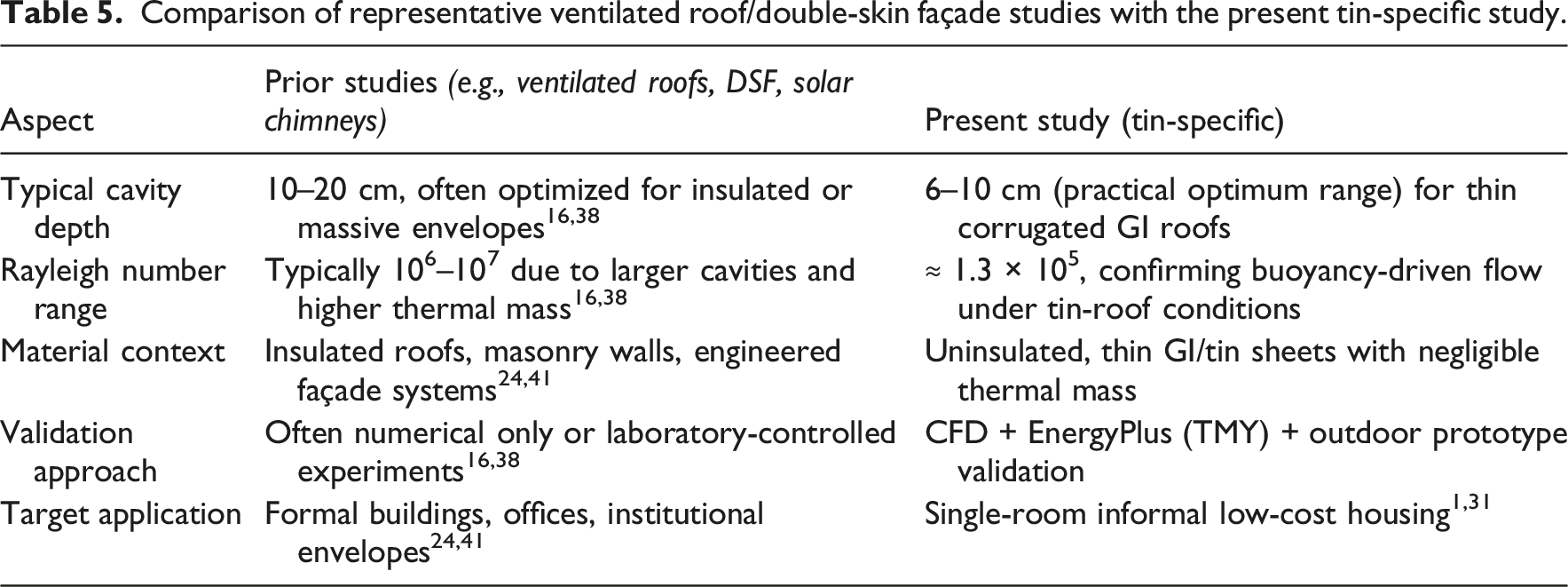
Prior ventilated roof and double-skin façade (DSF) studies have demonstrated that cavity ventilation can significantly reduce heat transfer to indoor spaces.16,38 However, most DSF investigations focus on conventional building envelopes such as insulated roofs, masonry walls, or engineered façade systems,24,41 and therefore do not directly represent single-room informal tin-sheet shelters. In such shelters, very low thermal mass, high radiative heat gains, corrugated sheet geometry, and construction-constrained cavity gaps fundamentally alter both the flow regime and the effective heat-transfer mechanisms.1,31
Tin-housing-specific findings
In comparison with prior ventilated roof and solar-chimney studies,16,38 the present results reveal three novel findings specific to tin-roof housing: (1) (2) (3)
Although the 1:3 prototype reproduced the geometric configuration of the proposed roof system, exact dynamic similarity with the full-scale shelter was not achieved because the Rayleigh number scales with the cube of the characteristic length (Ra ∝ L3). The prototype operated at Rayleigh numbers on the order of 105, whereas the corresponding full-scale shelter is expected to reach Rayleigh numbers of approximately 3.5 × 10⁶. This increase may promote stronger buoyancy-driven circulation and a transition toward a more turbulent natural-convection regime. Nevertheless, the governing heat-removal mechanism remains buoyancy-induced ventilation within the roof cavity. Consequently, the prototype was used primarily to validate the underlying physical cooling mechanism and the direction of thermal response, while full-scale performance predictions were obtained from CFD and EnergyPlus simulations using full-scale geometry. The higher Rayleigh numbers expected at full scale are anticipated to enhance convective heat removal rather than alter the fundamental cooling mechanism, suggesting that the prototype results may be considered conservative with respect to full-scale performance.
Comparison of representative ventilated roof/double-skin façade studies with the present tin-specific study.
A preliminary cost comparison for the Pune context (2024–2025 material prices) suggests that the double-tin ventilated roof requires approximately 1.8× the material cost of a single-layer GI roof (₹450–550 vs ₹250–300 per m2). However, this additional cost yields a measured indoor temperature reduction of 8–12°C under wind-assisted conditions, compared to cool-roof paint (₹80–120 per m2, 3–5°C reduction) and reflective insulation (₹200–300 per m2, 4–6°C reduction). On a cost-per-degree-reduced basis (₹ per m2 per °C), the ventilated double-tin roof (₹56–69) is comparable to reflective insulation (₹33–75) and higher than cool-roof paint (₹16–40), while offering the advantage of durability without reapplication (paint systems typically degrade within 1–2 years). For low-income households, the incremental cost associated with the second GI sheet may be offset by improved thermal comfort and reduced heat-stress risk, although upfront capital remains a constraint that could be mitigated through community-scale procurement strategies.
Summary of novelty
The novelty of this work lies in the systematic evaluation of a ventilated double-tin roof specifically for informal corrugated GI housing, supported by combined numerical and experimental evidence. First, the study identifies a practical, tin-specific optimal cavity range of 6–10 cm and explains the underlying physical mechanisms responsible for performance degradation beyond this range. Second, buoyancy-driven ventilation under realistic peak summer conditions is validated through an integrated framework combining CFD analysis, EnergyPlus simulations, and a 1:3 scale outdoor prototype with explicit consideration of scaling effects. Third, the work demonstrates a low-cost, construction-ready passive cooling solution tailored to climate-vulnerable informal housing contexts. As shown in Table 5, prior studies predominantly focus on insulated or high-performance building envelopes with larger cavity depths, whereas the present study addresses uninsulated, thin corrugated GI roofs typical of low-income dwellings. This study provides experimentally supported insights into ventilated double-tin roofing under real climatic conditions, integrating CFD, building simulation, and outdoor validation.
Conclusion
This study proposes and evaluates a 20° inclined double-tin ventilated roof as a low-cost passive cooling strategy for informal housing in hot climates. The methodology integrated three complementary approaches: (i) peak-load CFD analysis to resolve cavity airflow mechanisms and heat transfer, (ii) transient EnergyPlus simulations using TMY weather data to quantify diurnal indoor thermal response, and (iii) 1:3 scale outdoor prototype validation under summer conditions in Pune, India (18.5204° N, 73.8567° E).
Summary of key findings
Cavity-scale mechanisms (CFD)
The ventilated cavity established a stable buoyancy-driven upward draft with strong vertical stratification. The Rayleigh number (≈1.3 × 10⁵) confirmed laminar-to-transitional natural convection. Under peak solar loading (850–900 W/m2), the temperature difference across the 6 cm cavity reached 15–18°C, with the inner sheet stabilizing at 37–38°C. Relative to a conventional single-layer GI roof, the ventilated configuration reduced inward heat flux by 30%–35%.
Building-scale thermal response (EnergyPlus)
Using TMY weather data, the ventilated roof lowered indoor operative temperature by an average of 4–6°C during daytime hours, with a peak reduction of 6.2°C occurring at 13:00–14:00 local time. The system also delayed the peak indoor temperature by approximately 30 min relative to the single-layer baseline.
Experimental validation (prototype)
Outdoor prototype measurements confirmed the predicted trends: outer sheet temperatures reached 53–54°C (CFD: 55–57°C), inner sheet temperatures ranged 36–38°C (CFD: 37–38°C), and cavity temperature gradients measured 14–17°C (CFD: 15–18°C). The measured indoor air temperature reduction (8–12°C) exceeded the buoyancy-only CFD prediction (6.2°C) due to wind-assisted ventilation (0.5–2.0 m/s breezes during testing), consistent with wind–buoyancy coupling documented in the literature.15,16
Parametric design guidance
Gap-width sensitivity analysis (Figure 10) revealed a non-monotonic relationship: inner-sheet temperature decreased from 2 cm to 10 cm, then increased progressively at 12 cm and 14 cm. The minimum inner-sheet temperature (36.8°C) occurred at 10 cm. The performance degradation beyond 10 cm is attributed to three mechanisms: (i) plume detachment from the heated outer sheet, (ii) formation of recirculation regions that reduce convective extraction efficiency, and (iii) reduction in the driving temperature difference across the cavity. Based on these results, 6–10 cm is identified as the practical optimum range, balancing thermal performance with low-cost constructability (larger gaps require additional framing material and spacers).
The consistency between CFD-derived heat-flux reduction (30%–35%), EnergyPlus-predicted indoor cooling (4–6°C), and experimentally observed reductions (8–12°C under wind-assisted conditions) demonstrates robustness of the proposed ventilated roof across modelling scales and real-world conditions.
A preliminary cost comparison for Pune (2024–2025 material prices) indicates that the double-tin ventilated roof requires approximately 1.8× the material cost of a single-layer GI roof (₹450–550 vs ₹250–300 per m2), but delivers 8–12°C cooling versus 3–5°C for cool-roof paint (₹80–120 per m2), making it competitive on a cost-per-degree-reduced basis while requiring no periodic reapplication. The findings are consistent with broader literature on passive cooling in low-cost housing and ventilated envelope systems. 40
Primary contributions
This work makes three primary contributions to passive cooling research for informal housing: (1) (2) (3)
Limitations
Several limitations should be acknowledged: (1) (2) (3) (4) (5) (6) A limitation of the present sequential coupling approach is that the ventilation characteristics incorporated into EnergyPlus were derived from steady-state CFD simulations performed under representative peak summer conditions. In reality, buoyancy-driven airflow within the roof cavity varies throughout the day in response to changing solar radiation and surface temperatures. Consequently, the fixed ventilation parameters used in EnergyPlus may overestimate cavity airflow during early morning, late afternoon, and nighttime periods when buoyancy forces are weaker. However, because the principal objective of the study was to evaluate thermal performance during peak overheating conditions, the adopted approach was considered adequate for assessing the effectiveness of the proposed roof system. Future work may employ fully coupled transient CFD–building simulations to capture time-varying ventilation behaviour more accurately.
Future work
Based on these findings and limitations, future research should address: (1) (2) (3) (4) (5)
This study demonstrates that a 20° inclined double-tin ventilated roof with a 6–10 cm cavity gap can substantially reduce roof-driven heat gains in low-cost housing using only sheet-metal construction and passive ventilation. The approach requires no mechanical energy input, relies on widely available materials (corrugated GI sheets, spacers, basic framing), and is compatible with common informal construction practices. The results provide experimentally validated design guidance for a scalable, low-cost heat-stress mitigation strategy applicable to climate-vulnerable housing across hot-climate regions.1,4,6,31,40 The proposed solution offers a practical pathway for passive thermal comfort improvement in rapidly urbanizing, heat-vulnerable regions without reliance on energy-intensive cooling systems.
Footnotes

Funding
The authors received no financial support for the research, authorship, and/or publication of this article.
Declaration of conflicting interests
The authors declared no potential conflicts of interest with respect to the research, authorship, and/or publication of this article.