
Abstract
The mechanical behaviors of novel submicron silicon carbide (SiCsm)/ aluminum (Al)-micron silicon carbide (SiCm)/2024Al composites with a ductile–ductile-layered configuration are studied using experimental and multi-scale numerical simulation methods. To study the strengthening–toughening mechanism of the composites, we establish multi-scale representative volume elements (RVEs) at microscopic and mesoscopic scales in ABAQUS finite element software, where the micro-RVE contains SiCsm, Al matrix, and SiCsm/Al interfaces, which are used to predict the mechanical property of the SiCsm/Al element and the meso-RVE contains homogeneous cylindrical SiCsm/Al elements, SiCm, 2024 aluminum (2024Al) matrix, SiCm/2024Al interfaces, and layer interfaces. The tensile stress–strain relationship, damage, and failure behavior of the SiCsm/Al-SiCm/2024Al composites are simulated, which is consistent with the experimental tensile test results. A series of finite-element models of SiCsm/Al-SiCm/2024Al composites is established whose mechanical properties are calculated and the strengthening–toughening mechanism is analyzed. An optimization design method of synergizing microscopic mechanical properties with structural configuration has been developed for the strengthening–toughening trade-off of ductile–ductile-layered configuration composites, and the strengthening–toughening design of the SiCsm/Al-SiCm/2024Al composites is realized.
Keywords
Introduction
Advanced metal matrix composites with high strength and toughness have become indispensable key basic materials in many fields such as aerospace, automobile, and electronics.1–5 Configuration-based composites with material microstructure and performance as design factors have become one of the most important ways to break through the inverted strength–toughness relationship of traditional metal materials.6–8 Among them, layered configuration metal composites have been increasingly paid attention to and are widely used in various fields due to their high plasticity and toughening.9–11
In recent years, there have been many types of research of experimental preparation and testing on the configuration design and strengthening–toughening benefits of layered metal composites.12–15 Liu et al. 16 studied the bending behavior and fracture characteristics of five laminated Tie (TiBw/Ti) composites and found that the material properties shifted from toughness to brittleness when decreasing the thicknesses of the Ti layer or increasing the volume fractions of TiBw. Liu et al. 17 prepared a series of Ti-(TiBw/Ti) composites with different interface statuses and tested their tensile bending behavior, and the results showed that, with the increase of interfacial bonding strength and toughness, the material showed the highest tensile strength and elongation at break in the transverse direction. Xiang et al. 18 prepared carbon nanotubes/magnesium composites with micro-nano layered structures by imitating the pearly structure, achieving ultra-high strength and toughening efficiency of the material. Huang et al. 19 established a layered finite-element FE model to predict the damage behavior of metal laminated composites and analyzed the damage mechanism of Ti/ aluminum (Al)-layered composite with wavy interface morphology. Li et al. 20 tested the tensile mechanical properties of the TAl/5083 composite sheet through experiments and studied the microstructure evolution behavior and failure mechanism of the interface region during deformation. The results of the experimental test reveal that the key factors affecting the strength–toughness performance of layered metal composites include, among others, material volume fraction, layered configuration, interface morphology, and interface state.
A lot of research has been carried out on the experimental preparation and testing of layered metal composites; 21 however, the experimental approach is time-consuming and labor-intensive.22–24 Therefore, in recent years, researchers have begun to direct attention to the field of numerical modeling and the theoretical calculation of composites.25–41 A lot of studies have shown that FE modeling based on numerical calculations can not only realize the representative volume element (RVE) modeling of complex microstructures of composites but also simulate the mechanical and damage failure behavior.42–47 Liu et al. 48 conducted a model reconstruction of whisker-reinforced copper matrix (TiB/Cu) composites numerically based on their actual microstructure and the influence of the length of TiB whiskers on the mechanical properties such as tensile strength and elongation was analyzed, which provided theoretical support for the preparation and optimization of TiB/Cu. Zhang et al. 49 developed the FE model of particle-reinforced metal matrix composite (PRMMC), which can accurately predict the tensile stress–strain curve of PRMMC and quantitatively evaluate the effect of each strengthening mechanism. Zhang et al. 50 proposed a layered multi-scale method based on large-scale real digital microstructure models, which accurately and effectively predicted macroscopic and microscopic residual stresses in metal matrix composites. Xu et al. 51 studied the shape memory and pseudo elasticity effect of shape memory alloy fiber-reinforced composites through a 3D multi-scale FE method (FE2). Gao et al. 52 studied the effect of network structure on strength and fracture by FE modeling of three-dimensional network structures formed by particle- and rod-shaped SiC. In our previous work, 53 it was achieved that multi-scale FE research on the mechanical properties of nano-micron hybrid reinforced Al matrix composites by establishing nano-RVE and micro-RVE. Afterward, to study the mechanical properties of SiCp/CNT dual-scale hybrid reinforced Al matrix composites, we further proposed a multi-scale three-level FE numerical analysis method, covering the analysis range from nanoscale CNT/Al to micro-scale SiCp/(CNT/Al) and then to macroscopic specimen. 54
Experimental testing, theoretical calculations, and numerical simulations have shown that factors such as microstructure configuration, component materials, and interface properties play a crucial role in the strength and toughness of the mechanical properties of composites.55–58 Therefore, the establishment of accurate FE models and multi-scale analysis methods can help researchers better analyze the strengthening and toughening mechanism of composites, further realize the optimization design of mechanical properties of the composites, and provide design guidance for experiments. However, there are still few simulation calculations on the multi-scale mechanical properties of layered metal composites, which is important for the configuration design of layered metal composites. Therefore, in this paper, the mechanical behaviors of novel submicron silicon carbide (SiCsm)/Al-micron silicon carbide (SiCm)/2024Al composites with ductile–ductile-layered configuration are studied using experimental and multi-scale numerical simulation methods. The effects of structural configuration and layer interface properties on the strength and toughness properties of the composites are analyzed. Furthermore, the strengthening and toughening design of SiCsm/Al-SiCm/2024Al composites is achieved by coordinating the size of the SiCsm/Al elements and the strength of the layer interface.
The main research content framework is as follows. Section Materials and experimental procedures introduces the experimental raw materials and preparation process of the composites. In Section Finite-element modeling of SiCsm/Al-SiCm/2024Al composites, the FE modeling of multi-scale RVEs is carried out. In Section Analysis of strengthening–toughening mechanism and design of configuration and layer-interface-performance of SiCsm/Al-SiCm/2024Al composites, the strengthening–toughening mechanism is analyzed, and the design of configuration and layer-interface-performance of SiCsm/Al-SiCm/2024Al composites is realized.
Materials and experimental procedures
In this paper, SiCsm/Al-SiCm/2024Al-layered configuration composites are prepared using pure Al powder, SiCsm, 2024 Al alloy powder, and SiCm as raw materials. First, pure Al powder and submicron SiCps (mass ratio of 85:15) are added to stainless steel tanks filled with an argon atmosphere, and 1 wt.% stearic acid is used as a process control agent. SiCsm/Al flake powder is formed by a ball milled in a planetary ball mill. SiCsm/Al flake powder is then mechanically mixed with micron SiC and 2024Al powder (mass ratio of 1:1.7:0.3) in a nylon stirring tank to obtain composite powder (recorded as SiCsm/Al-SiCm/2024Al). The composite powder is densified by vacuum hot pressing sintering, extrusion, and other processes: Stearic acid is removed by degassing for 1 h under vacuum conditions (< 1 Pa) and temperature of 773 K and then sintered for 10 min at 853 K in a Φ37.5 mm mold; the sintering process was carried out at a uniaxial pressure of 300 MPa. The sintered billet ingots are hot extruded into bars (673 K, ratio of 22:1), and the solution is treated at 768 K for 1.5 h, quenched in water, and then aged at 443 K for 4 h. For comparison, SiCsm/Al powder is prepared by powder assembly and SiCm/2024Al powder by mechanical blending, and two other homogeneous composites are obtained, which are recorded as SiCsm/Al and SiCm/2024Al, respectively.
Figure 1(a) and (b) presents the microstructures of the SiCsm/Al-SiCm/2024Al composites. From the longitudinal section, as shown in Figure 1(a), it can be seen that there is a clear layered configuration of the SiCsm/Al element and the SiCm/2024Al element. From the cross-section, as shown in Figure 1(b), it can be seen that the SiCsm/Al element is randomly and uniformly distributed in the SiCm/2024Al element. Combining Figure 1 (a, b), it can be observed that the SiCsm/Al element is randomly and uniformly distributed vertically in the SiCm/2024Al element in an approximately cylindrical shape. By measuring statistics, the layer thickness of SiCsm/Al is 42.68 ± 11.46 μm, and the layer thickness of SiCm/2024Al is 46 ± 18.76 μm. Figure 1 (c) shows the standard electronic nodules (SEM) image of the SiCsm/Al composites, and the SEM image of the SiCm/2024Al composites is shown in Figure 1(d).
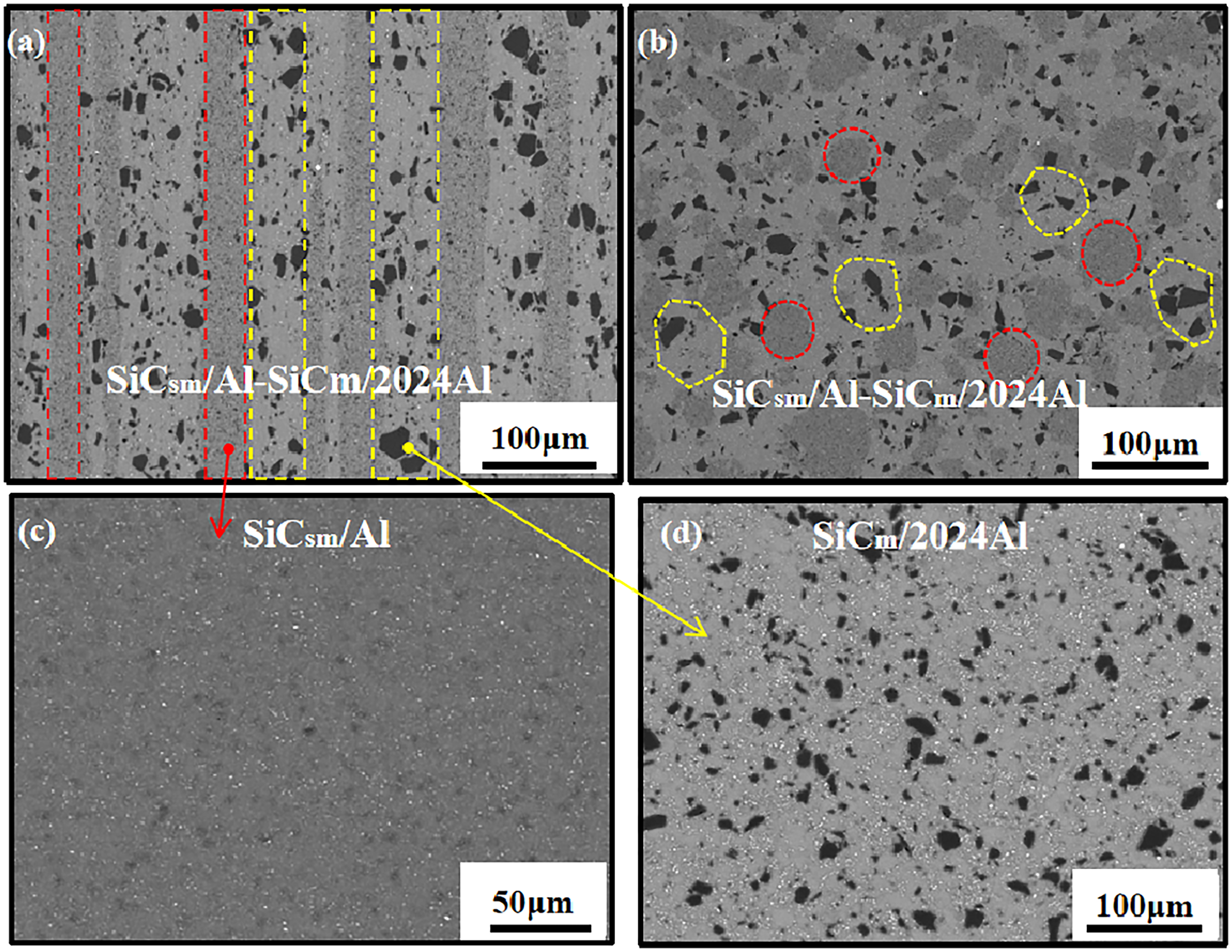
SEM images of (a) the longitudinal section of SiCsm/Al-SiCm/2024Al composites, (b) the cross-section of SiCsm/Al-SiCm/2024Al composites, (c) SiCsm/Al composites, (d) siCm/2024Al composites. SiCsm, submicron silicon carbide; SiCm, micron silicon carbide.
To test the tensile mechanical properties of the three composites, tensile specimens were machined along the extrusion direction with a gage length of 15 mm and a cross-section of 3.5 mm × 1.5 mm. Tensile testing is performed at a constant strain rate of 5 × 10⁻⁴s−1 on a universal testing machine (Zwick Z20) at room temperature. A set of experimental data for each composite comes from more than three tensile test results. The tensile fracture morphologies of the three composites are shown in Figure 2, in which Figure 2(a–c) are profile fracture surfaces of the SiCsm/Al-SiCm/2024Al composites, SiCsm/Al composites, and SiCm/2024Al composites and Figure 2 (d–f) are fractography.
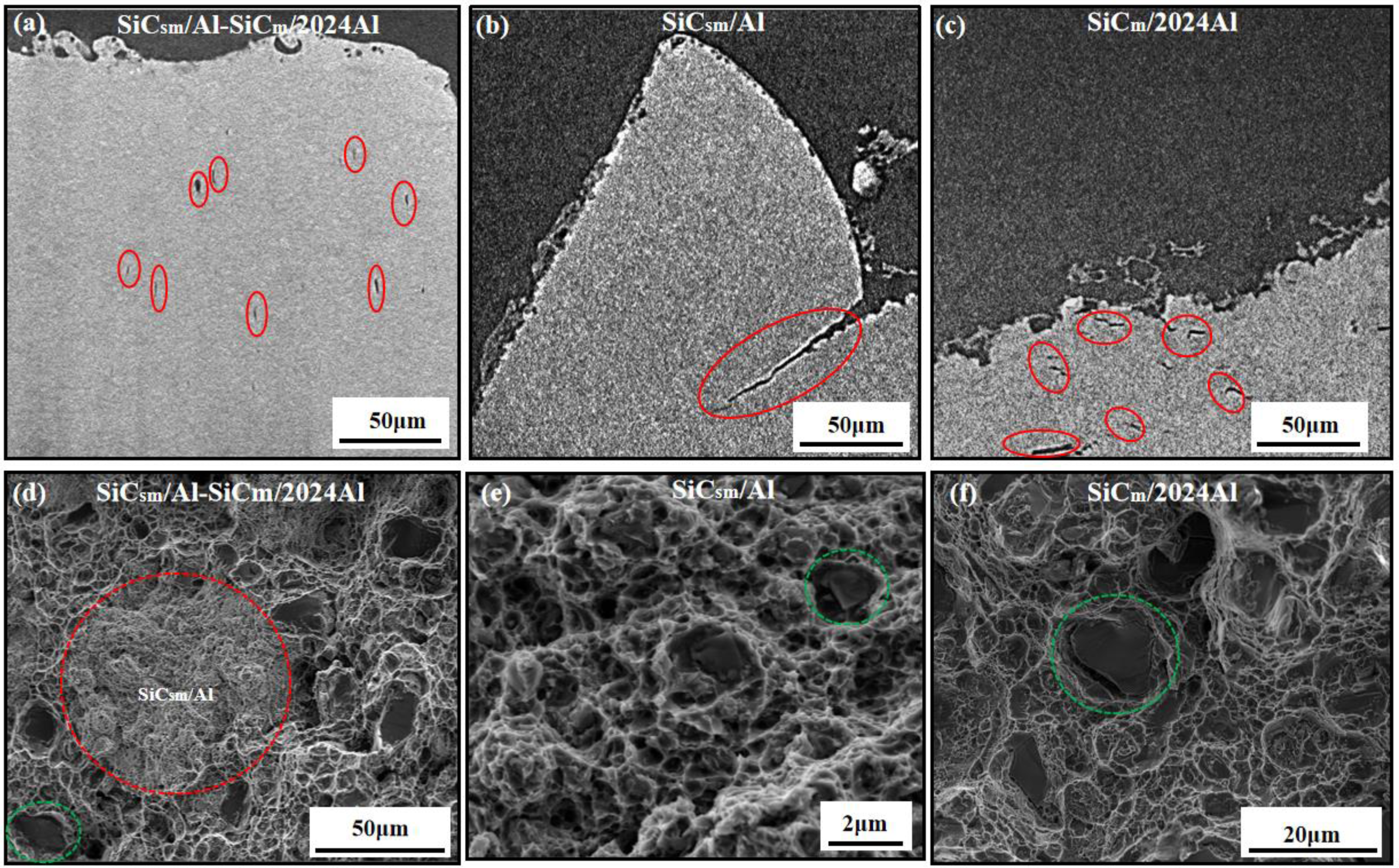
The profile fracture surfaces of (a) SiCsm/Al-SiCm/2024Al composites, (b) SiCsm/Al composites, (c) SiCm/2024Al composites; the fractographies of (d) SiCsm/Al-SiCm/2024Al composites, (e) SiCsm/Al composites, (f) SiCm/2024Al composites. SiCsm, submicron silicon carbide; SiCm, micron silicon carbide.
Finite-element modeling of SiCsm/Al-SiCm/2024Al composites
Through experimental observation, the microstructures of the SiCsm/Al-SiCm/2024Al composites, the SiCsm/Al composites, and the SiCm/2024Al composites are obtained (see Figure 2). There are multi-scale characteristics of the SiCsm/Al-SiCm/2024Al-layered configuration composites, which is consistent with the experimental preparation process. At the meso-scale, a layered configuration composite consisting of the SiCsm/Al element and the SiCm/2024Al element can be observed in which the SiCsm/Al element is randomly and uniformly distributed vertically in the form of a homogeneous material similar to a columnar. At the meso-scale, it can be seen that the SiCm/2024Al element is a composite composed of SiCm and 2024Al, while the SiCsm/Al element is a homogeneous material. At the micro-scale, the SiCsm/Al element is a composite composed of SiCsm and Al.
Combined with experimental testing and analysis, the scale separation of the microstructures of the layered configuration composites is carried out, and the details of the material composition and structure at each scale are determined. In Section Finite-element modeling of SiCsm/Al-SiCm/2024Al composites, the FE modeling of multi-scale RVEs of the SiCsm/Al-SiCm/2024Al composites is described in detail. In addition, the FE modeling of contrasting SiCsm/Al composites and SiCm/2024Al composites is also carried out, where the RVE scale of the SiCsm/Al composites is at the micro-scale and the RVE scale of the SiCm/2024Al composites is at the meso-scale.
Micro-scale RVE model
Geometric model and boundary conditions
The micro-scale RVE can characterize both the SiCsm/Al element of the SiCsm/Al-SiCm/2024Al composites and the SiCsm/Al composites. In Figure 3(a), the dimensions of the micro-scale RVE in the modeling are 5 μm × 5 μm × 5 μm and the SiCsm particles are simulated as polyhedrons53,54 with an average particle radius of 0.7 μm. The SiCsm particles with a volume fraction of 15% are randomly distributed in the Al matrix, whose volume fractions and particle radius can be changed according to the actual situation. To describe the mechanical behavior of the interface between the SiCsm particles and the Al matrix, the zero-thickness cohesion elements meshed with COH3D6 elements are established. For the Al matrix and SiCsm, C3D4 elements are adopted. There are 11229 FE nodes and 57919 elements in the micro-scale RVE mesh refinement. The periodic boundary conditions are usually preferred for the prediction of mean effective response; however, in micro-scale RVE, SiCsm particles are randomly distributed in the composites, so absolute periodicity cannot provide good estimates. In addition, periodic boundary conditions are not applicable when discussing the problem of large deformation and fracture. The research by Zhang and Cugnoni et al. shows that the displacement-controlled boundary condition is more suitable for fracture damage simulation of composites and matches the uniaxial tensile situation in the experiment.59–61 As shown in Figure 3(b), all nodes located on the lower surface are fixed with all degrees of freedom. A reference point (RP) is established, which is coupled with the upper surface node shown in Figure 3(c), to apply a displacement load UZ along the Z direction at RP.
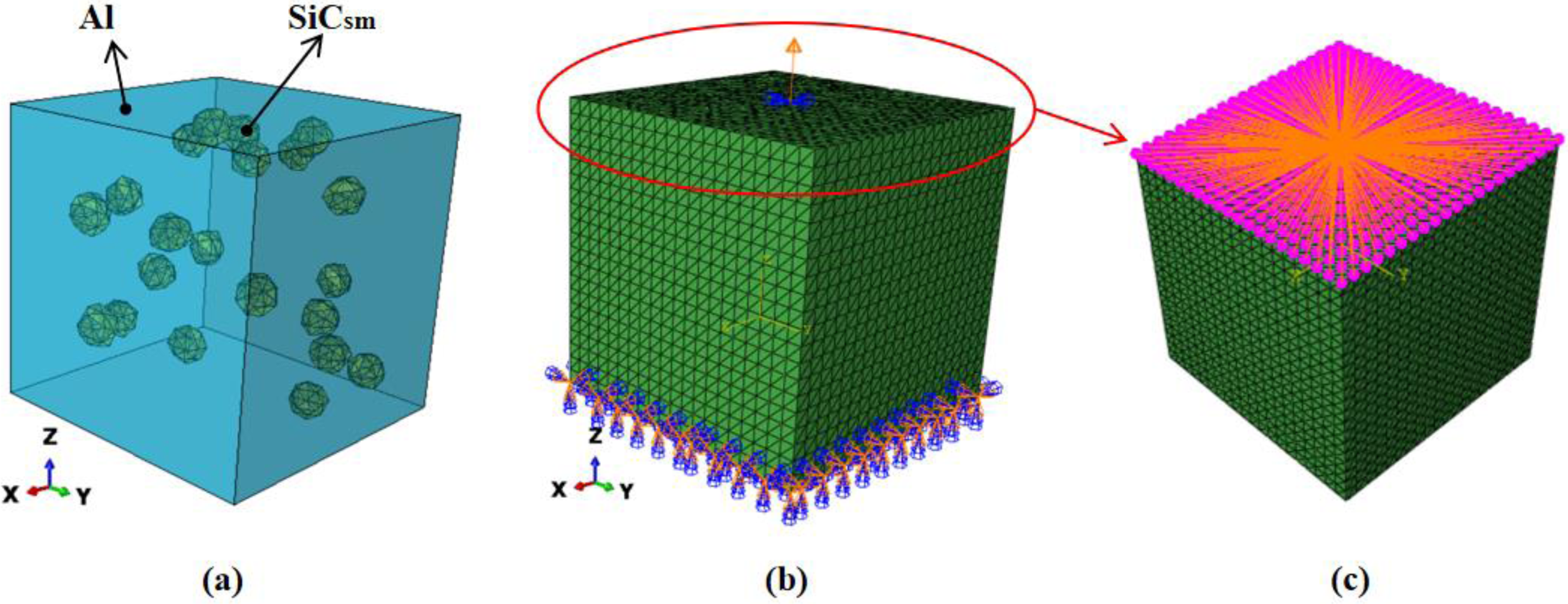
(a) The micro-scale RVE with 15vol% SiCsm/Al, (b) and (c) the load and boundary conditions in the Z direction. RVE, representative volume element; SiCsm, submicron silicon carbide.
Material properties
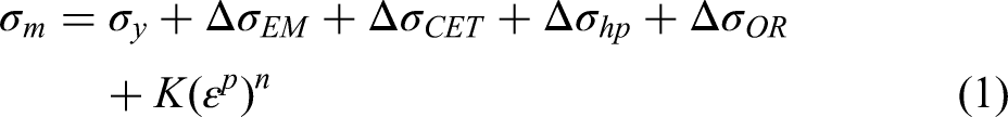
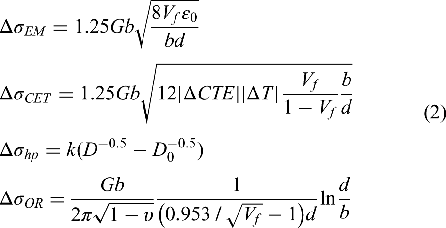
The mechanical properties of SiCsm and the Al matrix are provided by experimental testing. According to Figure 2(e), the SiCsm almost did not break during the tensile fracture process, so the SiCsm is set as linear elastic materials. The material property of Al is elastoplastic. Table 1 shows the material parameters of SiCsm and Al. The flow stress of Al is described by Ludwik's law,53,54 and the strengthening effects on Al are considered, which are geometrically necessary dislocation caused by the mismatch of elastic modulus and coefficient of thermal expansion between SiCsm and the Al matrix,44,60 fine-grain strengthening and Orowan strengthening
62
caused by submicron particles, expressed as Equations (1) and (2). The material parameters and values are shown in Table 2.
The material parameters of SiCsm and Al.
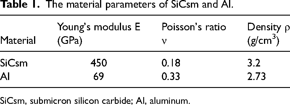
SiCsm, submicron silicon carbide; Al, aluminum.
The material parameters and values of Al and 2024Al.
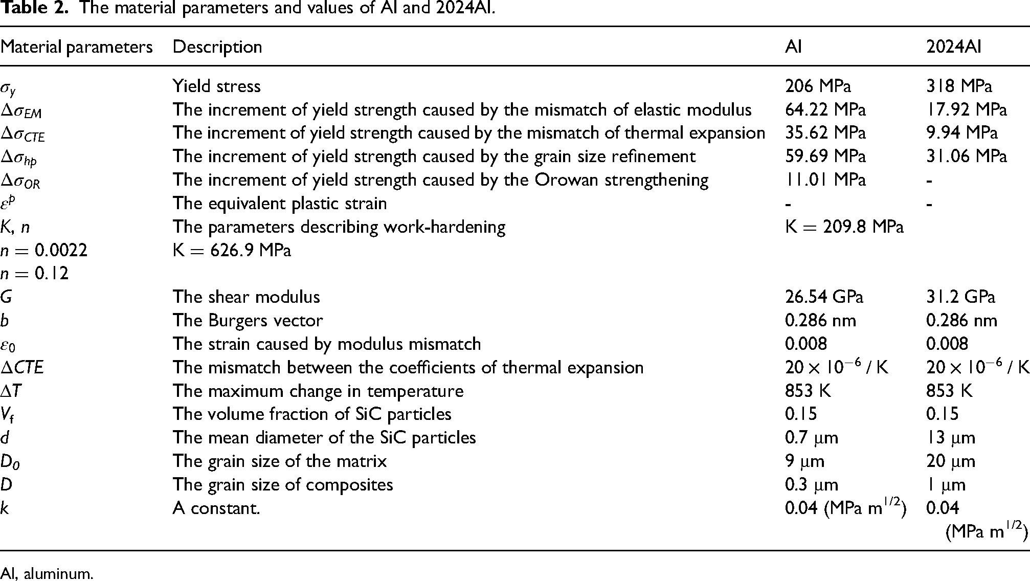
Al, aluminum.
There is a debonding phenomenon at the interface between SiCsm and the Al matrix observed in Figure 2 (e). To characterize the interface between SiCsm and the Al matrix, it is modeled as a bilinear cohesive element with traction-separation behavior. Figure 4 shows the traction-separation law with linear softening of the cohesion model.
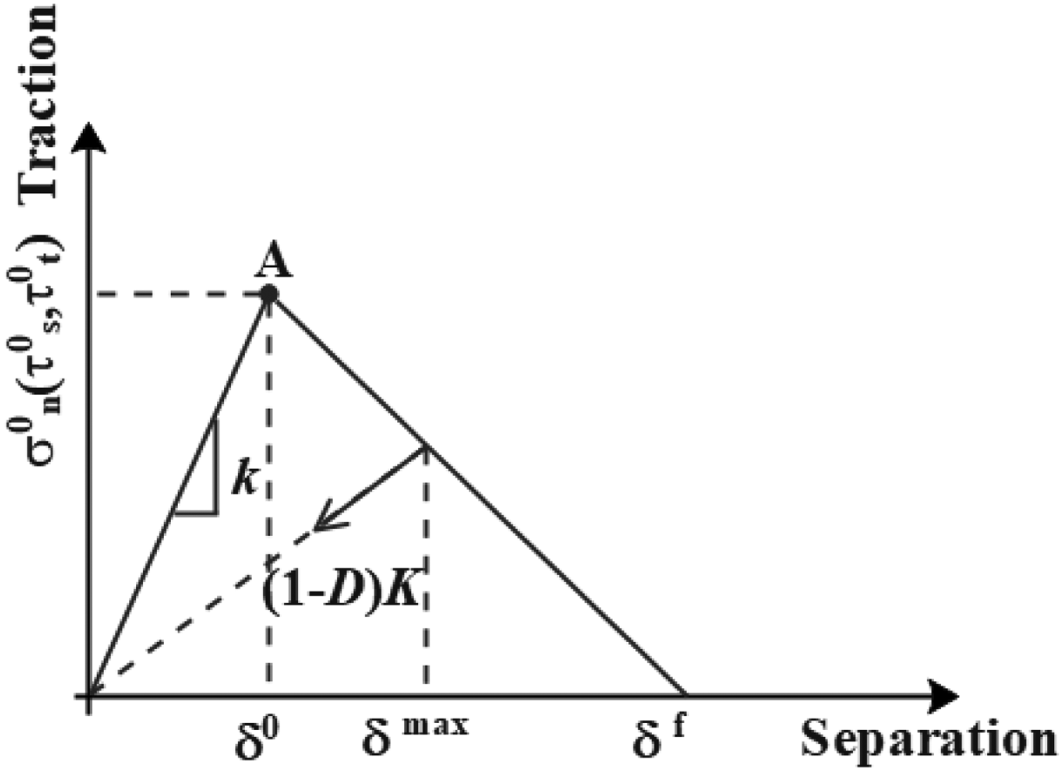
The traction-separation law with linear softening of cohesion model.
Before point A, the linear elastic constitutive equation is used to describe the mechanical behavior: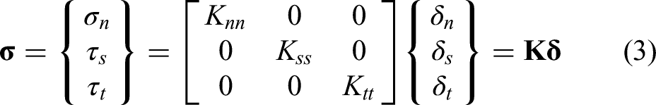
Interface damage begins at point A, predicted by the secondary stress failure criterion,
63
expressed as Equation (4):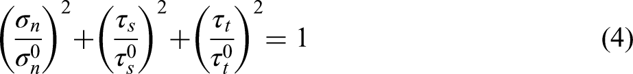
Three interface phase properties in FE models.

SiCsm, submicron silicon carbide; SiCm, micron silicon carbide; Al, aluminum.
After point A, the degree of damage to the interface is determined by the stiffness degradation criterion. The stiffness degradation coefficient is defined as D, expressed as Equation (5):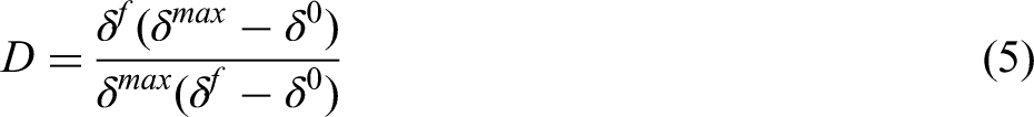
To simulate the damage and fracture behavior of the Al matrix, the ductile fracture model considering damage evolution from previous work is used,
34
as shown in Figure 5. The material first undergoes the elastic-plastic stage of a-b-c. The initiation of material damage occurs at point C and the equivalent plastic strain at the onset of damage is defined as
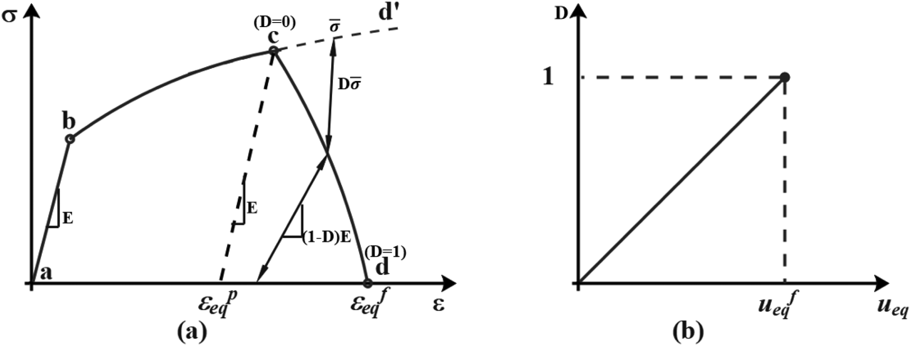
The models of (a) ductile fracture and (b) damage evolution.
Meso-scale RVE model
Geometric model and boundary conditions
The geometric modeling method of the meso-scale RVE of the SiCm/2024Al composites is the same as that of the SiCsm/Al composites. In Figure 6, the dimensions of the RVE of the SiCm/2024Al composites are 100 μm × 100 μm × 100 μm and the average particle radius of the SiCm particles is 13μm. The 15vol%SiCm particles are distributed in the 2024Al matrix randomly. Between the SiCm particles and the 2024Al matrix, there are zero-thickness cohesion elements that characterize the interface. Herein we adopt C3D4 elements for the 2024Al matrix and SiCm and COH3D6 elements for the interface. In this FE model, there are 12175 FE nodes and 64027 elements for the RVE mesh refinement.

The meso-scale RVE of the 15vol% SiCm/2024Al. RVE, representative volume element; SiCm, micron silicon carbide.
As shown in Figure 7, the meso-scale RVE of the SiCsm/Al-SiCm/2024Al composites consists of four components: the SiCsm/Al element, the SiCm/2024Al element, the interface between SiCm and 2024Al, and the layer interface between the SiCsm/Al element and the SiCm/2024Al element. Figure 7 (b) shows the SiCsm/Al elements, which are cylinders with a diameter of 42 μm and a height of 190 μm. Figure 7(c) shows the SiCm/2024Al element, which is a composite material composed of SiCm and the 2024Al matrix. The ratio of volume fractions of the SiCsm/Al element and the SiCm/2024Al element is 1:2. Figure 7(d) shows the layer interface between the SiCsm/Al element and the SiCm/2024Al element. Figure 7(e) shows the interface between SiCm and 2024Al. All the interface is modeled as zero-thickness cohesion elements. In addition, it should be noted that the mechanical properties calculation of the SiCsm/Al element comes from the homogenization calculation of micro-scale RVE. 33 Herein, the boundary conditions of the meso-scale RVE are consistent with those of the micro-scale RVE (see Figure 3).
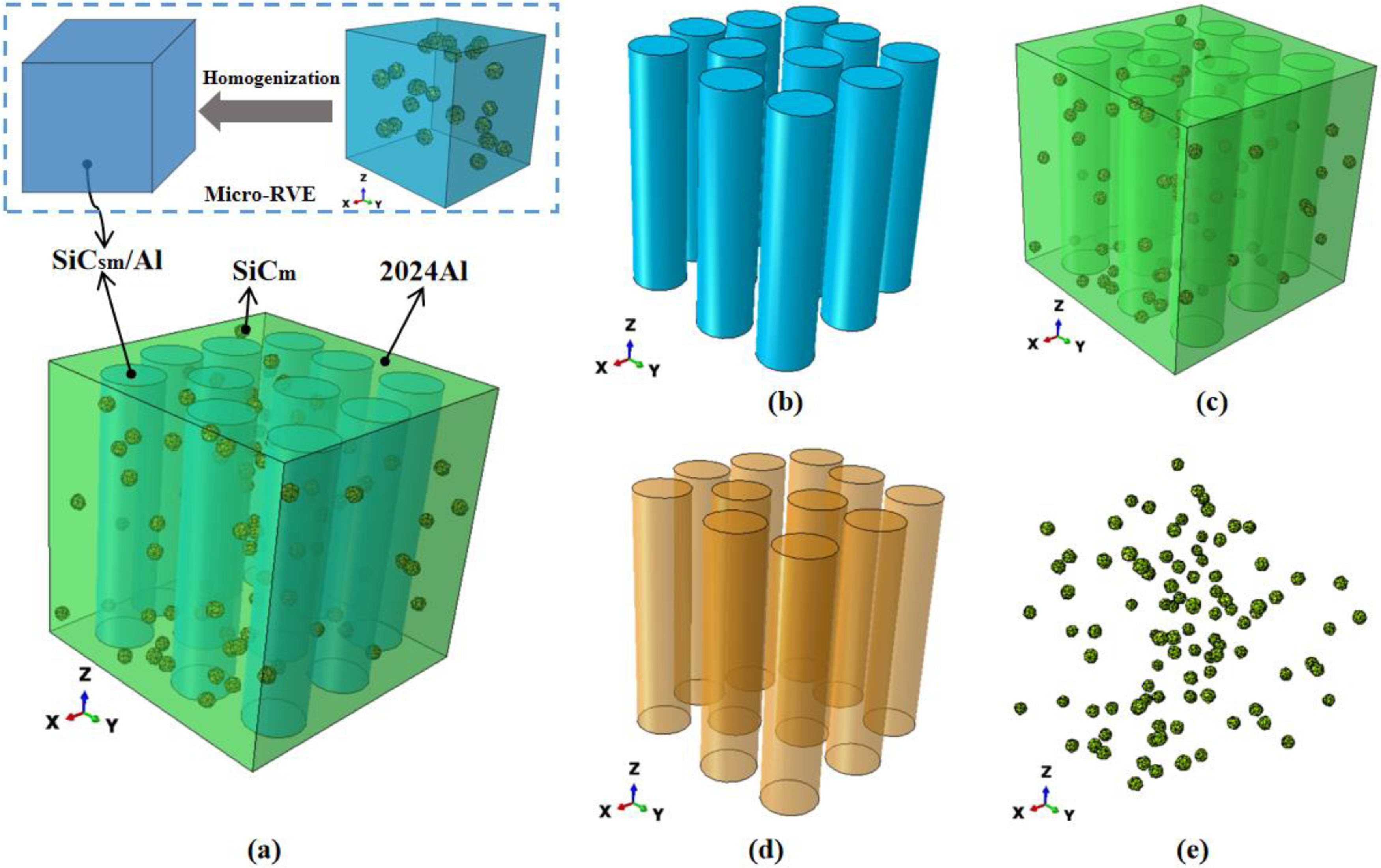
(a) The meso-scale RVE of SiCsm/Al-SiCm/2024Al composites, (b) SiCsm/Al elements, (c) SiCm/2024Al element, (d) the layer interface between SiCsm/Al element and SiCm/2024Al element, and (e) the interface between SiCm and 2024Al. RVE, representative volume element; SiCsm, submicron silicon carbide; SiCm, micron silicon carbide; Al, aluminum.
Material properties
There are two meso-scale RVEs: One is the SiCm/2024Al composites and the other is the SiCsm/Al-SiCm/2024Al composites. The material properties of the SiCm are the same as those of SiCsm. The flow stress equation of 2024Al is the same as that of Al, only changing the relevant material parameters (see Table 2). The material constitutive model of all the interface phases is modeled as a bilinear cohesive element mentioned in Section Material properties, and Table 3 shows the material properties of the three interface phases. At present, it is difficult to obtain the data of the interfacial strength between the particles and the matrix and the layer interfacial strength between the SiCsm/Al element and the SiCm/2024Al element through experimental tests, so these parameters are numerically extrapolated by fitting the tensile stress–strain curves of the SiCsm/Al composites, the SiCm/2024Al composites and the SiCsm/Al-SiCm/2024Al composites, respectively.
In meso-scale RVE, the material parameters of the SiCsm/Al element in the SiCsm/Al-SiCm/2024Al composites are obtained through homogenization calculation using the volume average method64,65 of the SiCsm/Al composites in micro-scale RVE. The equivalent stress–strain curve of the SiCsm/Al element is shown in the green dashed line in Figure 8. The Young's modulus of the SiCsm/Al element in the meso-scale RVE is calculated as 89.59 GPa. A digitized version of stress–strain relationships to describe the plastic material properties of the SiCsm/Al element is shown in Table 4. It can be seen from the green dashed line in Figure 8 that there is ductile damage mechanics performance in the SiCsm/Al element and we use the ductile fracture model considering the damage evolution model described in Section Micro-scale RVE model. From the green dashed line in Figure 8, the fracture strain value is determined as
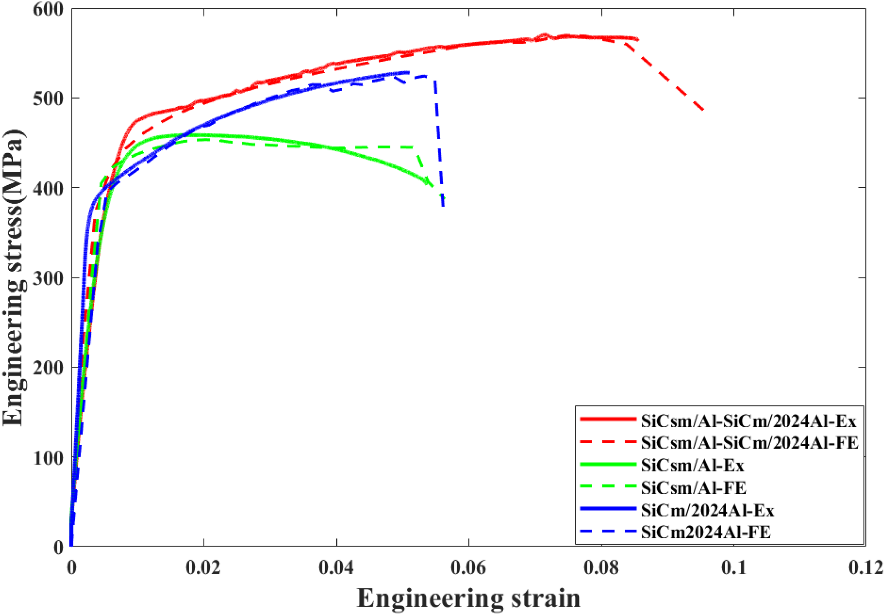
The equivalent stress–strain curves of SiCsm/Al-SiCm/2024Al composites, SiCsm/Al composites, and SiCm/2024Al composites. SiCsm, submicron silicon carbide; SiCm, micron silicon carbide; Al, aluminum.
Yield stress versus equivalent plastic strain for the SiCsm/Al element.
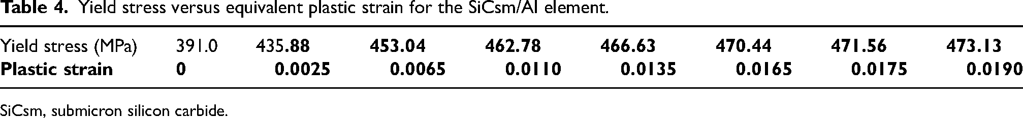
SiCsm, submicron silicon carbide.
Finite-element model verification
The tensile stress–strain relationships of the three composites are obtained through tensile testing, as shown in Figure 8. In Figure 8, there are six equivalent stress–strain curves. The three solid curves are the tensile experimental test results mentioned in Section Materials and experimental procedures, and the other dashed curves are the FE simulation results. The red, green, and blue curves represent the stress–strain curves of the SiCsm/Al-SiCm/2024Al composites, the SiCsm/Al composites, and the SiCm/2024Al composites, respectively. From Figure 8, the FE simulation results are in good agreement with the experimental test results. Therefore, the multi-scale FE model proposed in this article is accurate and effective in simulating and predicting the comprehensive mechanical behavior of the SiCsm/Al-SiCm/2024Al ductile–ductile-layered configuration composites.
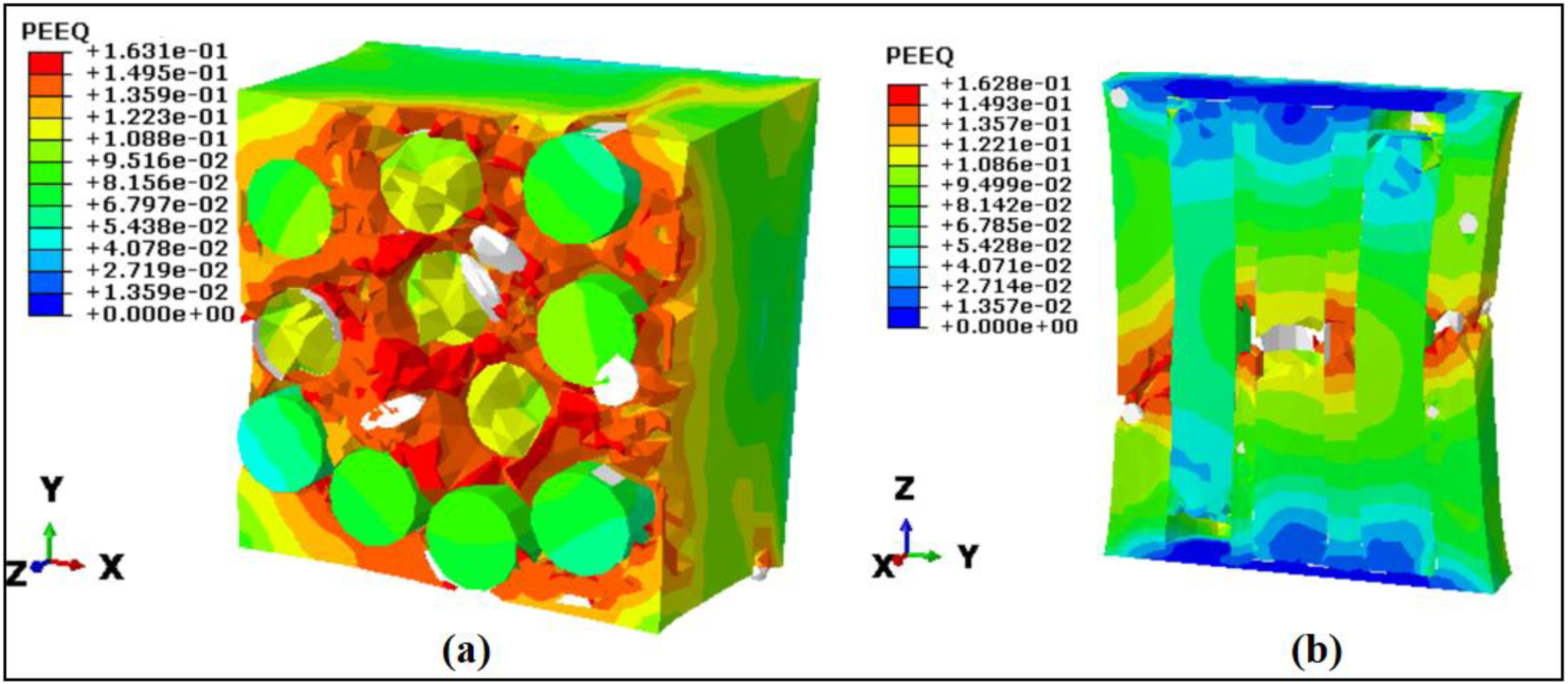
As shown in Figures 9 and 10, the stress and strain contour plots of the SiCsm/Al-SiCm/2024Al composites during loading are extracted, respectively. As shown in Figure 9, during the deformation process, the stress value in the SiCm/2024Al element with higher Young's modulus is greater than that in the SiCsm/Al element. According to the strain contour plots (see Figure 10), it can be concluded that during the deformation process, there is a complex damage process of the SiCsm/Al-SiCm/2024Al composites. The damage begins with the debonding of the layer interface between the SiCsm/Al element and the SiCm/2024Al element, and further, necking and fracture occur in the SiCsm/Al element. Eventually, as the SiCm/2024Al element gradually fractures, the cracks in the composites connect, and the material fails. In addition, in Figures 9 and 10, the damage morphology and distribution of the SiCsm/Al-SiCm/2024Al composites are marked with white ellipses, which are in good agreement with the fracture morphology shown in the experimental results (see Figure 2(a)).
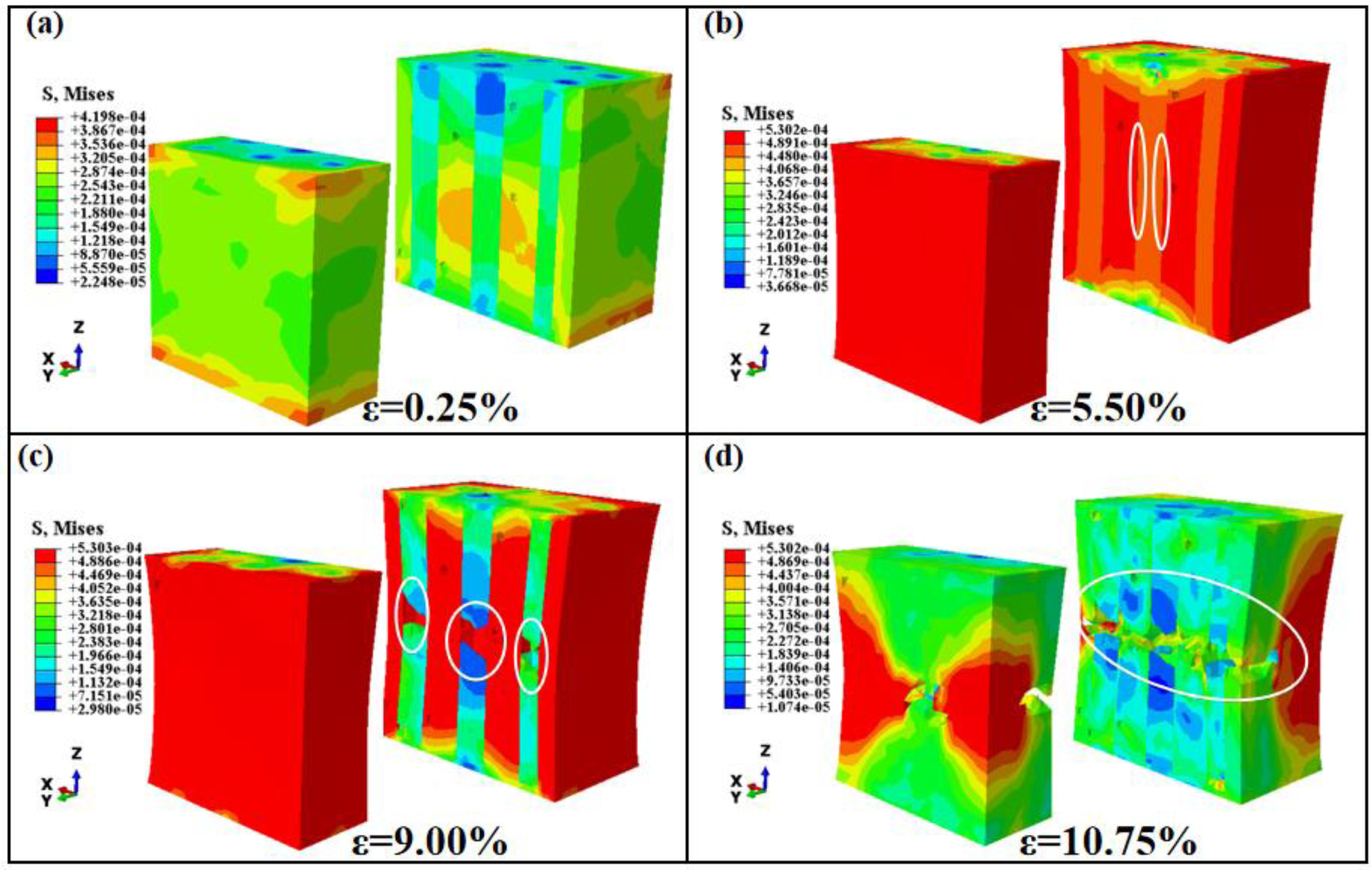
The strain contour plots of the SiCsm/Al-SiCm/2024Al composites. SiCsm, submicron silicon carbide; SiCm, micron silicon carbide.
The strain contour plots of the SiCsm/Al-SiCm/2024Al composites. SiCsm, submicron silicon carbide; SiCm, micron silicon carbide.
Analysis of strengthening–toughening mechanism and design of configuration and layer-interface-performance of SiCsm/Al-SiCm/2024Al composites
In Section Finite-element modeling of SiCsm/Al-SiCm/2024Al composites, the mechanical properties of the SiCsm/Al-SiCm/2024Al-layered configuration composites, the SiCsm/Al composites, and the SiCm/2024Al composites are simulated and calculated through the FE method. It is found that, compared with SiCsm/Al and SiCm/2024Al, SiCsm/Al-SiCm/2024Al has not only an increased yield strength but also a significantly increased fracture toughness. To maximize the advantages of the SiCsm/Al-SiCm/2024Al-layered configuration composites, we analyzed their tensile fracture mechanism and calculated the mechanical properties of the composites by changing the configuration parameters and layer interface strength. Finally, the fracture toughness is greatly improved but the yield strength is not reduced, avoiding the disadvantage of strength–toughness inversion, by coordinating the configuration parameters and the layer interface strength.
The effect of element size on the strength–toughness of composites
Changing the radius size of the SiCsm/Al element, a series of SiCsm/Al-SiCm/2024Al-layered configuration composites are established as shown in Figure 11, ensuring a certain volume fraction ratio of the SiCsm/Al element to the SiCm/2024Al element (1:2).
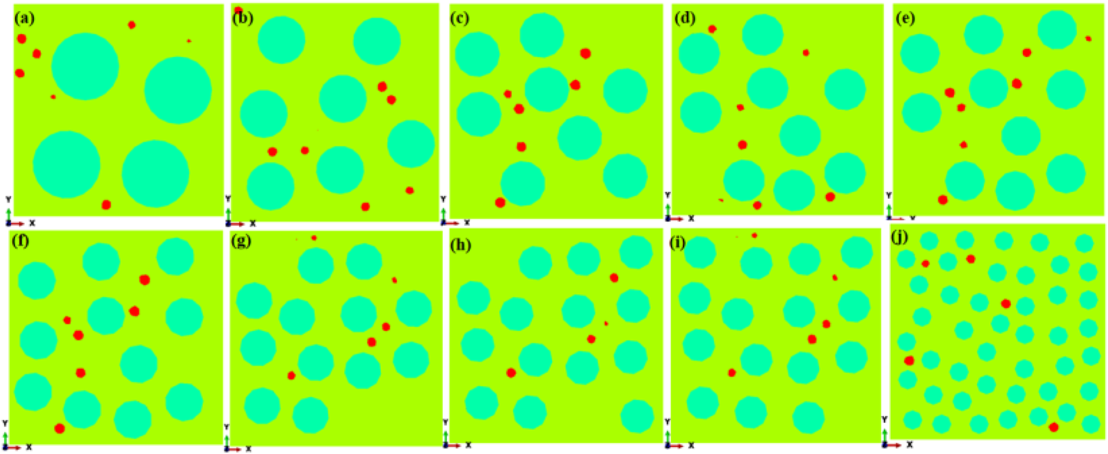
Ten configurations of SiCsm/Al-SiCm/2024Al-layered configuration composites, whose radius of SiCsm/Al element is (a) r = 35 μm, (b) r = 25 μm, (c) r = 24.11 μm, (d) r = 23 μm, (e) r = 21.9 μm, (f) r = 21 μm, (g) r = 20.2 μm, (h) r = 19 μm, (i) r = 18 μm, (j) r = 12 μm. SiCsm, submicron silicon carbide; SiCm, micron silicon carbide; Al, aluminum.
The tensile stress–strain curves are calculated for the 10 configurations of the SiCsm/Al-SiCm/2024Al composites, and the results are shown in Figure 12. Comparing the ten stress–strain curves, it is found that the fracture toughness of the composites is the best when r = 23 μm and r = 12 μm, but the strength of the composites decreases slightly in these two cases, especially when r = 12 μm; When r = 35 μm and r = 25 μm, the fracture toughness of the composites is extremely poor: that is, when the size of the SiCsm/Al element is too large, it will be greatly reduced.
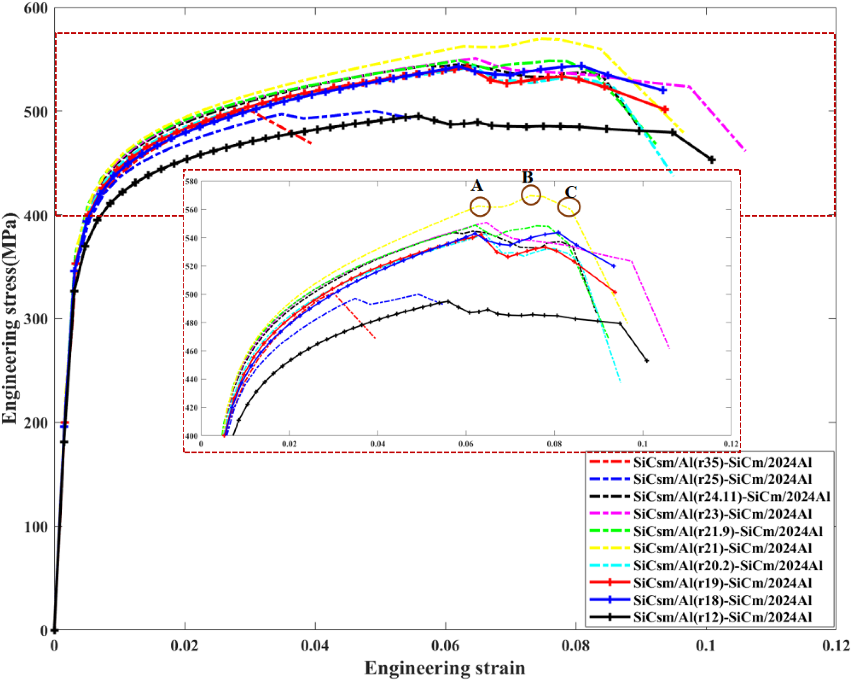
The equivalent stress–strain curves of 10 configurations of SiCsm/Al-SiCm/2024Al composites. SiCsm, submicron silicon carbide; SiCm, micron silicon carbide; Al, aluminum.
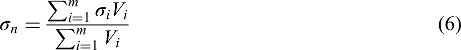
To analyze the influence of configuration on the load-bearing capacity of composites, the stress concentration factors of composites with the three configurations r = 21 μm, r = 12μm, and r = 35 μm are calculated. First, the average stress of each element in the composites is calculated as Equation (6):
66
Then, the effective stress can be calculated by Equation (7):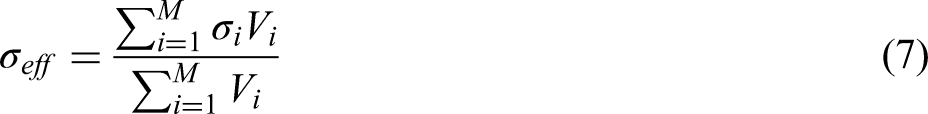
The stress concentration factor f can be expressed as Equation (8):
Figure 13 shows the stress concentration factors of SiCsm/Al(r21)-SiCm/2024Al, SiCsm/Al(r12)-SiCm/2024Al, and SiCsm/Al(r35)-SiCm/2024Al. Taking SiCsm/Al(r21)-SiCm/2024Al as the research object, comparing the stress–strain curve (Figure 12) and stress concentration factor (Figure 13), it is found that there are three turning points A, B, and C in the stress–strain curve of the SiCsm/Al(r21)-SiCm/2024Al composites during tensile fracture, which correspond to the stress concentration factor graph. Moreover, fSiCsm/Al(r21) element has a strong fluctuation, indicating that the fracture toughness of the composites is mainly affected by the SiCsm/Al element. At point A, the SiCsm/Al element begins to fracture; during the A–C process, the SiCsm/Al element continuously produces new fractures and causes a redistribution of load in the composites, resulting in the phenomenon of fracture steps. However, in SiCsm/Al(r35)-SiCm/2024Al, because the size of SiCsm/Al(r35) is too large, it is not easy to fracture, and there is no fracture ladder phenomenon in the composites, which also proves that this ladder fracture mechanism is conducive to improving the fracture toughness of the composites. Although there is the fracture ladder phenomenon in SiCsm/Al(r12)-SiCm/2024Al, the small-sized SiCsm/Al(r12) element leads to stress concentration, leading to premature yielding of the composites and reducing its strength.
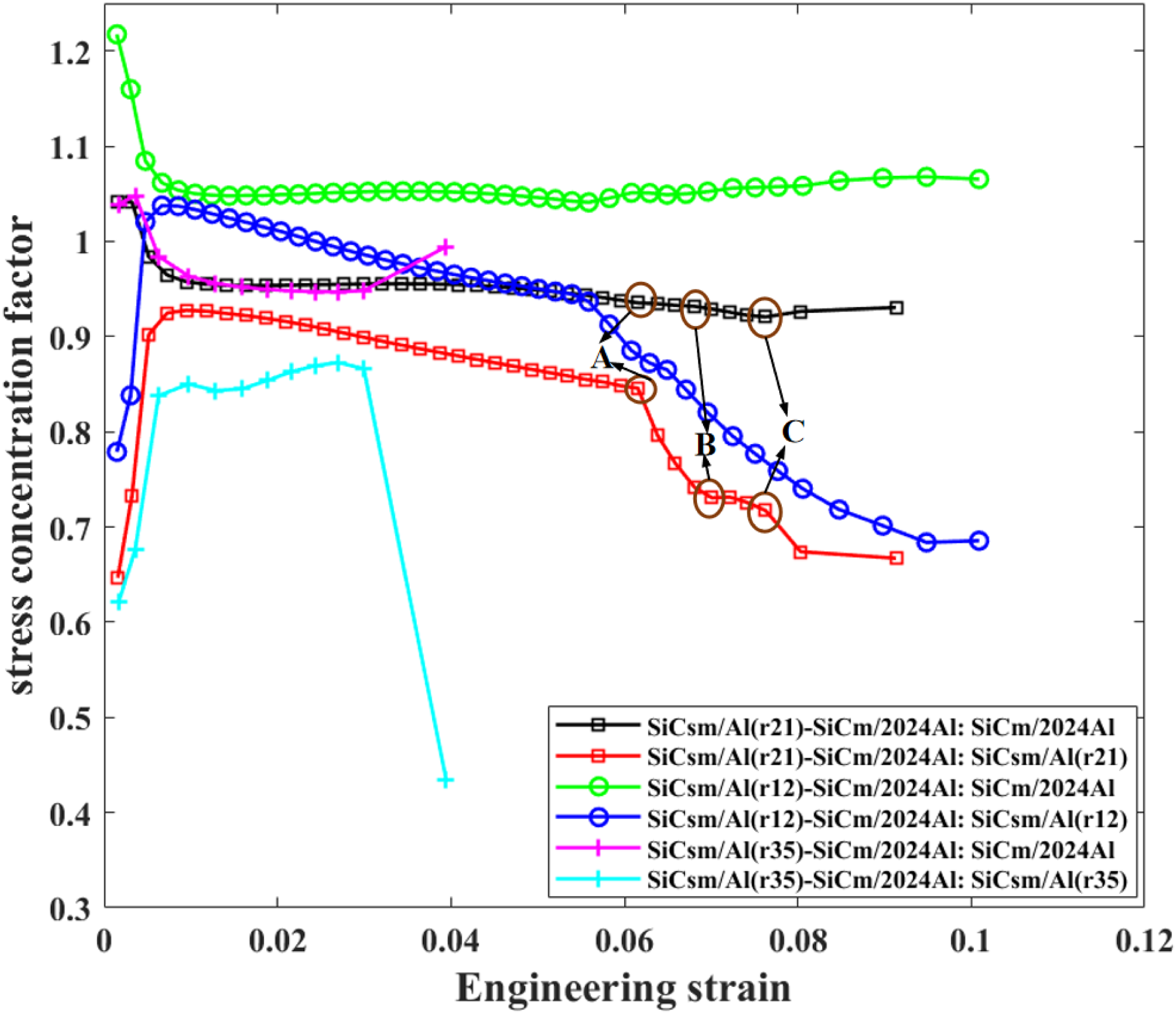
Stress concentration factors of SiCsm/Al(r21)-SiCm/2024Al, SiCsm/Al(r12)-SiCm/2024Al, and SiCsm/Al(r35)-SiCm/2024Al. SiCsm, submicron silicon carbide; SiCm, micron silicon carbide; Al, aluminum.
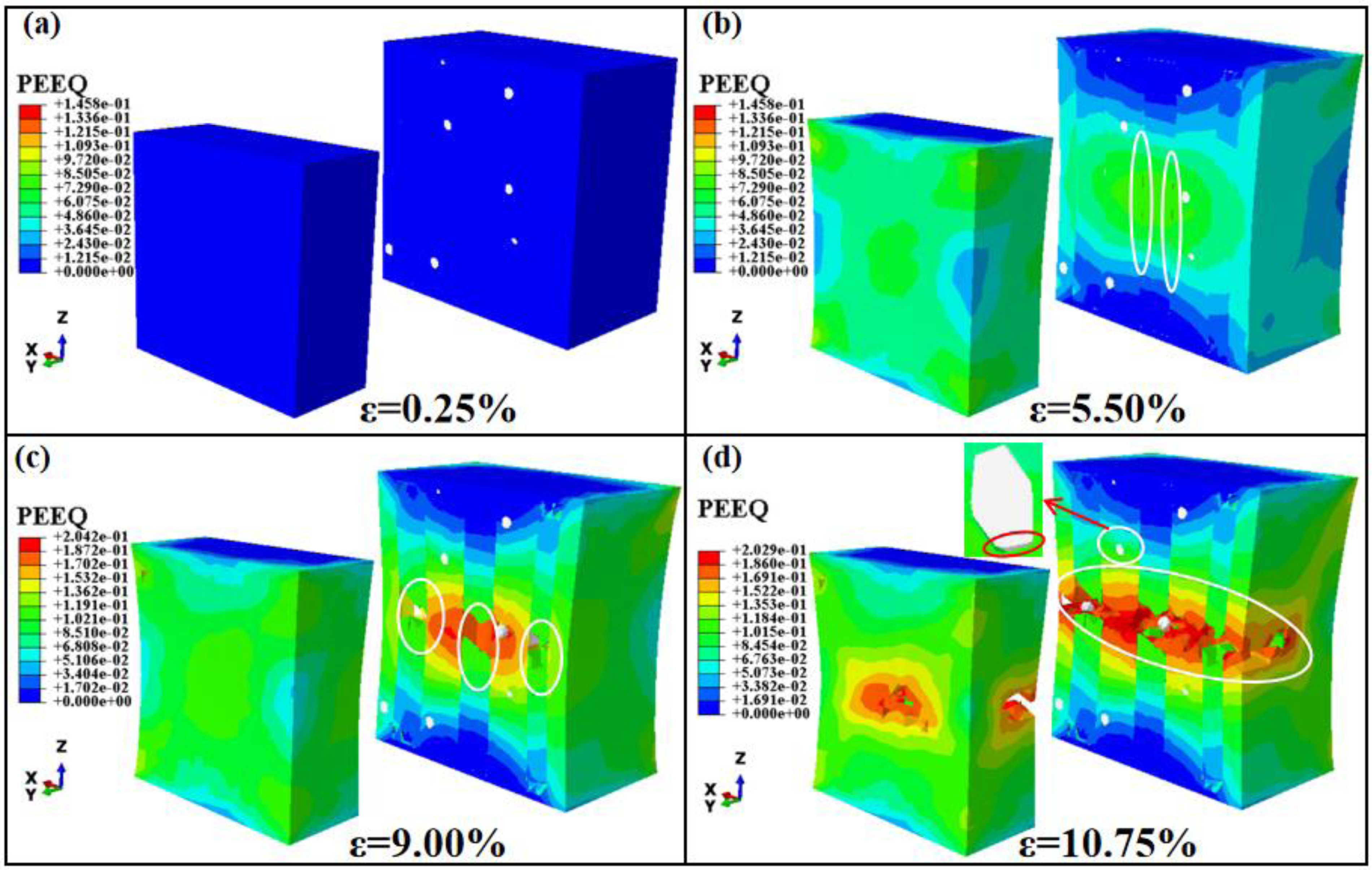
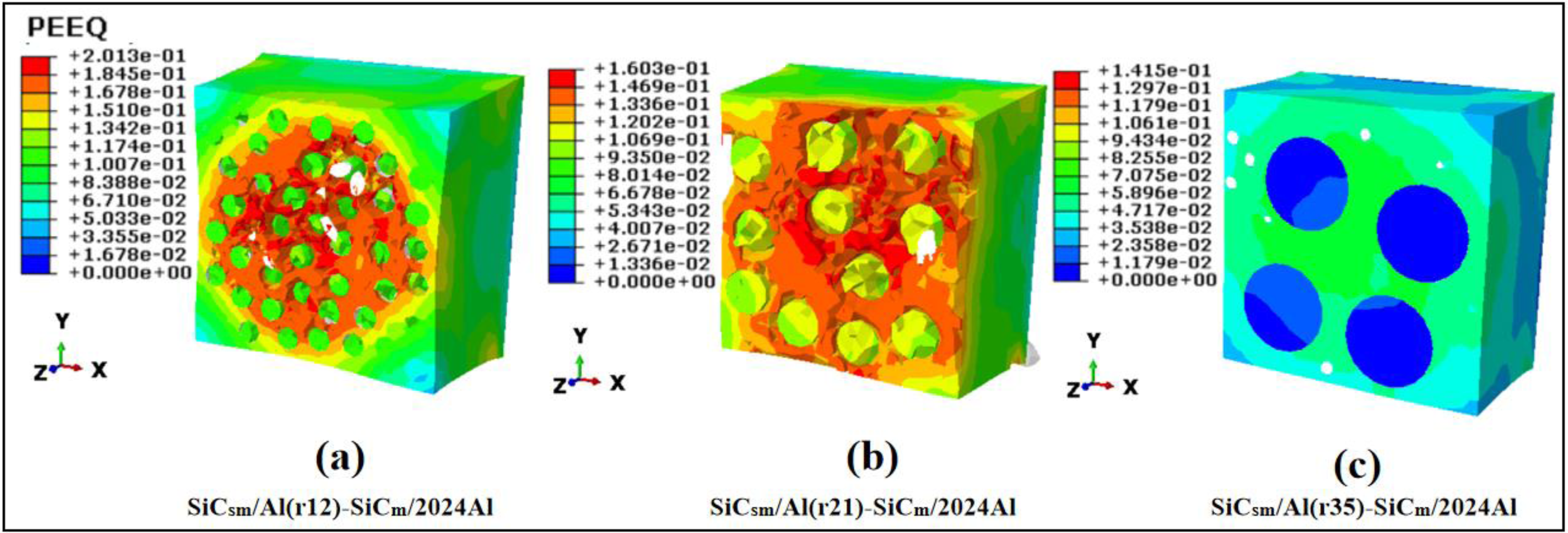
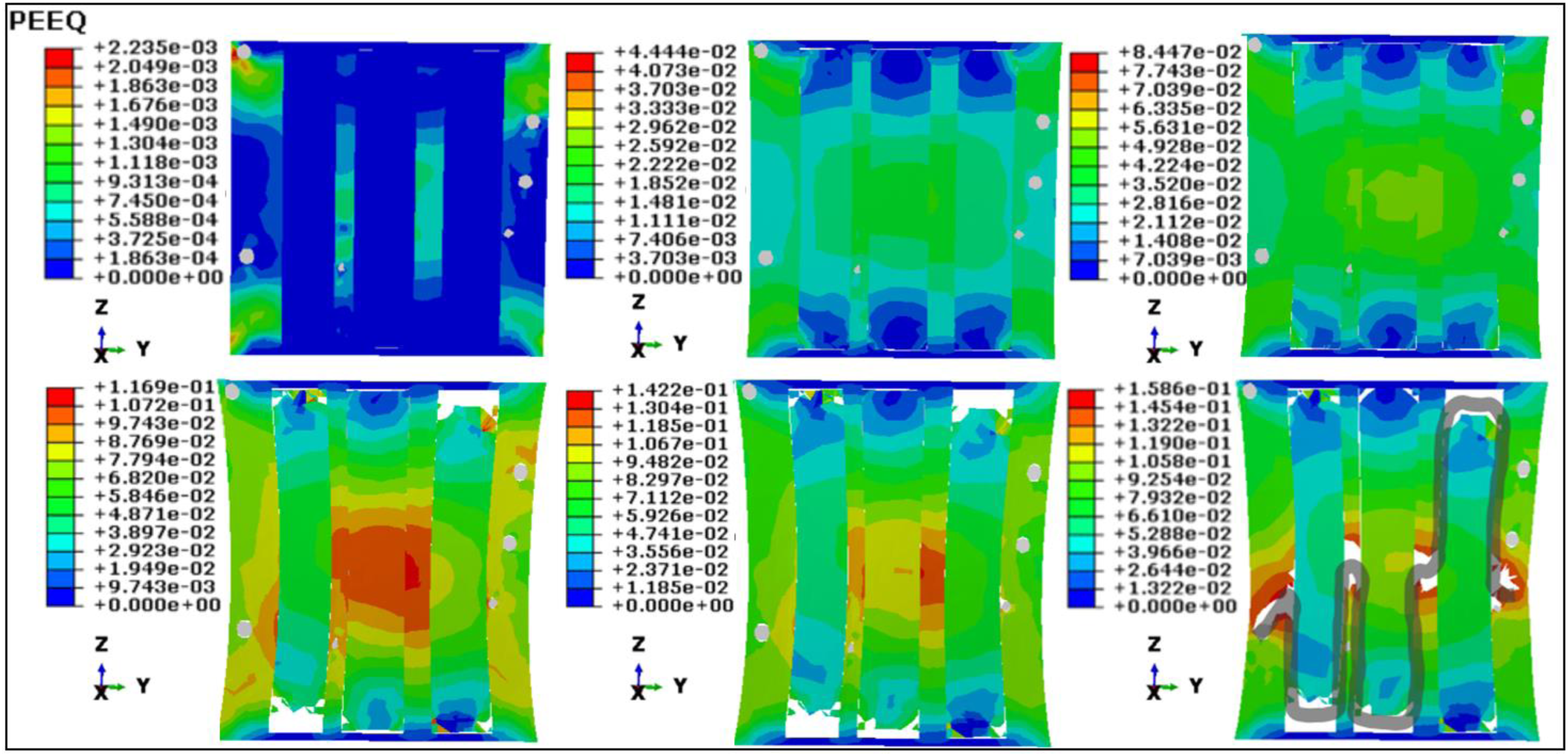
Furthermore, the strain contour plots of the composites in Figure 14 are extracted to analyze the damage evolution process. By analyzing the progressive damage evolution contour plots of SiCsm/Al(r21)-SiCm/2024Al, the damage and fracture mechanism of the layered configuration composites is revealed.

The strain contour plots of SiCsm/Al(r12)-SiCm/2024Al, SiCsm/Al(r21)-SiCm/2024Al, and SiCsm/Al(r35)-SiCm/2024Al. SiCsm, submicron silicon carbide; SiCm, micron silicon carbide; Al, aluminum.
As shown in Figure 14 (b-2), transverse cracking at the layer interface between the SiCsm/Al element and the SiCm/2024Al element is generated first, and then longitudinal cracking at the layer interface between the SiCsm/Al element and the SiCm/2024Al element is generated, and there is also the interface debonding between SiCm and 2024Al. As the load increases, ductile damage occurs in the SiCsm/Al layer, which accumulates and forms cracks, as shown in Figure 14 (b-4). Due to the obstruction of the SiCm/2024Al layer, the cracks in SiCsm/Al layer stop propagating between the layers, so the existence of the SiCm/2024Al layer causes crack bridging in the layered composites, as shown in Figure 14 (b-5). At the same time, the SiCm/2024Al layer undergoes large plastic deformation behavior, which plays the role of crack shielding and passivation to a certain extent. Therefore, it can be concluded that the SiCm/2024Al ductility layer can reduce the stress strength factor at the crack, thereby hindering the further propagation of the crack, which ultimately improves the fracture toughness of the layered composites. Combined with the stress–strain curve (Figure 12) and the stress concentration factor curve (Figure 13), it is found that the hierarchical fracture phenomenon of the SiCsm/Al layer also benefits from this layered configuration.
Comparing Figure 14 (a, b), when the size of the SiCsm/Al element is smaller, the composites are less prone to transverse cracking and are more prone to longitudinal cracking at the layer interface between the SiCsm/Al element and the SiCm/2024Al element, which leads to obvious local deformation concentration. Finally, when the composites fracture, the necking deformation of SiCsm/Al(r12)-SiCm/2024Al is more severe than that of SiCsm/Al(r21)-SiCm/2024Al, as seen Figure 14 (a-6) and (b-6). From the fracture morphology shown in Figure 15 (a) and (b), it can also be seen that the degree of local deformation and necking deformation of SiCsm/Al(r12)-SiCm/2024Al is significantly higher than that of SiCsm/Al(r21)-SiCm/2024Al.
The fracture morphology of SiCsm/Al(r12)-SiCm/2024Al, SiCsm/Al(r21)-SiCm/2024Al, and SiCsm/Al(r35)-SiCm/2024Al. SiCsm, submicron silicon carbide; SiCm, micron silicon carbide; Al, aluminum.
Comparing Figure 14 (b) and (c), when the size of the SiCsm/Al element is larger, the composites are more prone to transverse cracking and are almost not prone to longitudinal cracking at the layer interface between the SiCsm/Al element and the SiCm/2024Al element. The main deformation form of the SiCsm/Al layer is the shear deformation at the end position, while the SiCm/2024Al layer only undergoes small plastic deformation locally. This configuration leads to premature separation of the SiCsm/Al layer and the SiCm/2024Al layer in the load direction in the composites and to premature tunnel cracks in the composites, which ultimately leads to material failure. From the fracture morphology shown in Figure 15 (c), when the composites fail, the SiCsm/Al layer has almost no deformation and the SiCm/2024Al layer has only minimal deformation.
Through the above analysis, it is concluded that the size of the SiCsm/Al element that is too large or too small is not conducive to the strong and tough performance of the composites. Therefore, by changing the size of the SiCsm/Al element incrementally within the range of r = 24 μm to r = 20 μm, four other configurations of the composites are designed and their mechanical properties are simulated and calculated. There are the equivalent stress–strain curves of five configurations of the SiCsm/Al-SiCm/2024Al composites in Figure 16 (a) and the stress concentration factors curves of SiCsm/Al(r21)-SiCm/2024Al, SiCsm/Al(r24)-SiCm/2024Al, and SiCsm/Al(r20)-SiCm/2024Al in Figure 16 (b). It can be seen that the fracture toughness of SiCsm/Al(r24)-SiCm/2024Al is the best among the five configurations, while the strength of SiCsm/Al(r24)-SiCm/2024Al decreases slightly compared with that of SiCsm/Al(r21)-SiCm/2024Al.
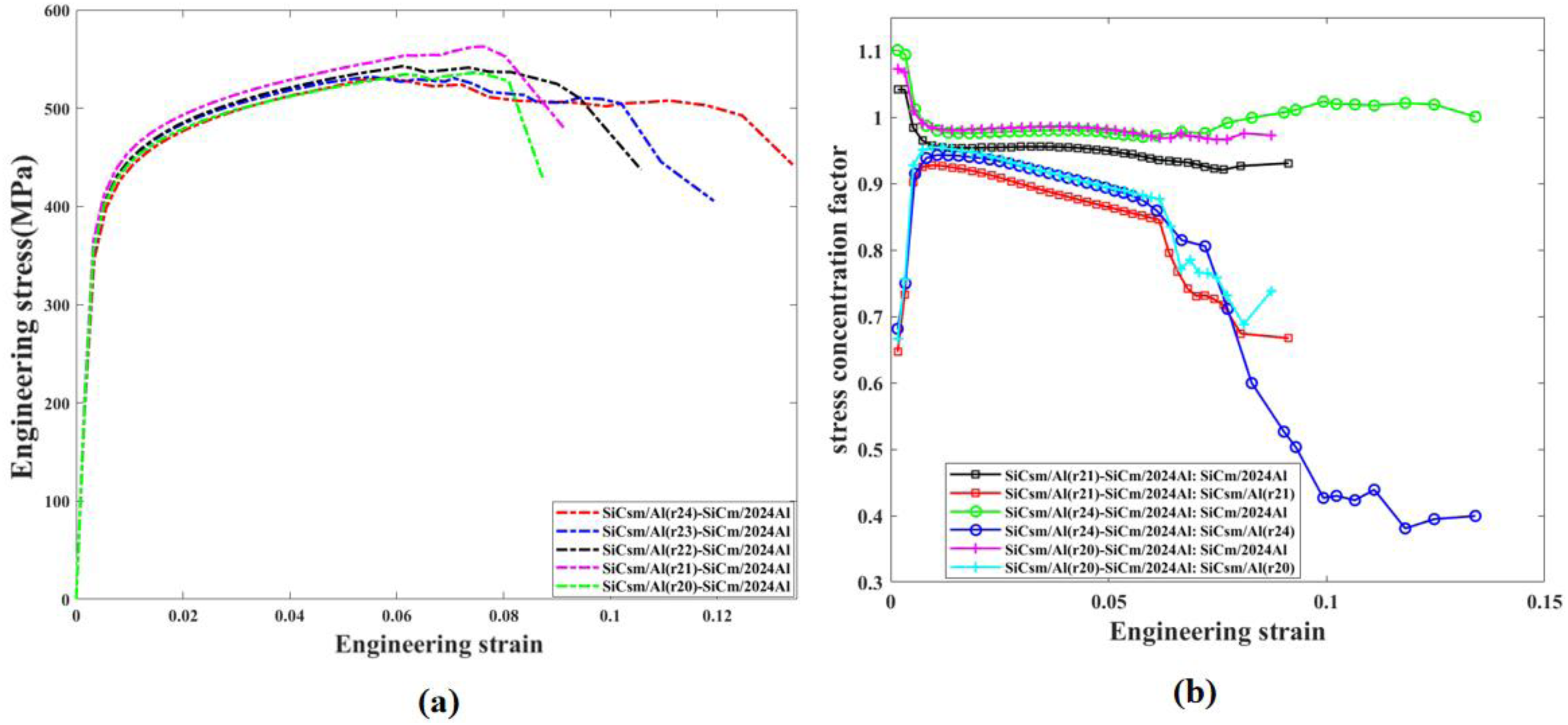
(a) The equivalent stress–strain curves of five configurations of SiCsm/Al-SiCm/2024Al composites, (b) stress concentration factors of SiCsm/Al(r21)-SiCm/2024Al, SiCsm/Al(r24)-SiCm/2024Al, and SiCsm/Al(r20)-SiCm/2024Al. SiCsm, submicron silicon carbide; SiCm, micron silicon carbide; Al, aluminum.
To analyze the fracture mechanism of SiCsm/Al(r24)-SiCm/2024Al, the progressive damage contour plot is extracted (see Figure 17). Comparing Figures 14 and 17, there are six types of damage forms in SiCsm/Al(r24)-SiCm/2024Al: transverse debonding at the layer interface between the SiCsm/Al element and the SiCm/2024Al element, longitudinal debonding at the layer interface between the SiCsm/Al element and the SiCm/2024Al element, interface debonding between the SiCm and 2024Al, ductility damage of the SiCsm/Al element, ductility damage of the SiCm/2024Al element, and shear failure of the SiCsm/Al element. As damage accumulates, there are various forms of cracks generated in the SiCsm/Al(r24)-SiCm/2024Al composites, including ductile cracks of SiCsm/Al layer, tunnel cracks of SiCsm/Al layer, ductile cracks of the SiCm/2024Al layer, and delamination cracks between the SiCsm/Al layer and the SiCm/2024Al layer. The rich crack form in the composites increases the crack length during the fracture process as shown in Figure 17(6) and improves the fracture toughness.
The strain contour plot of SiCsm/Al(r24)-SiCm/2024Al. SiCsm, submicron silicon carbide; SiCm, micron silicon carbide; Al, aluminum.
The effect of layer-interface-performance between elements on the strength–toughness of composites
A series of FE models are established for the SiCsm/Al(r21)-SiCm/2024Al composites whose layer interface strengths are set to 50 MPa, 70 MPa, 100 MPa, 200 MPa, and 300 MPa, and their mechanical properties are calculated. Figure 18 (a) shows the equivalent stress–strain curves and Figure 18 (b) shows stress concentration factors of the SiCsm/Al-SiCm/2024Al composites with layer interface strengths of 50 MPa, 70 MPa, 100 MPa, 200 MPa, and 300 MPa. It can be seen from Figure 18 that with the increase in layer interface strength, the strength of the composites increases while the fracture toughness decreases.
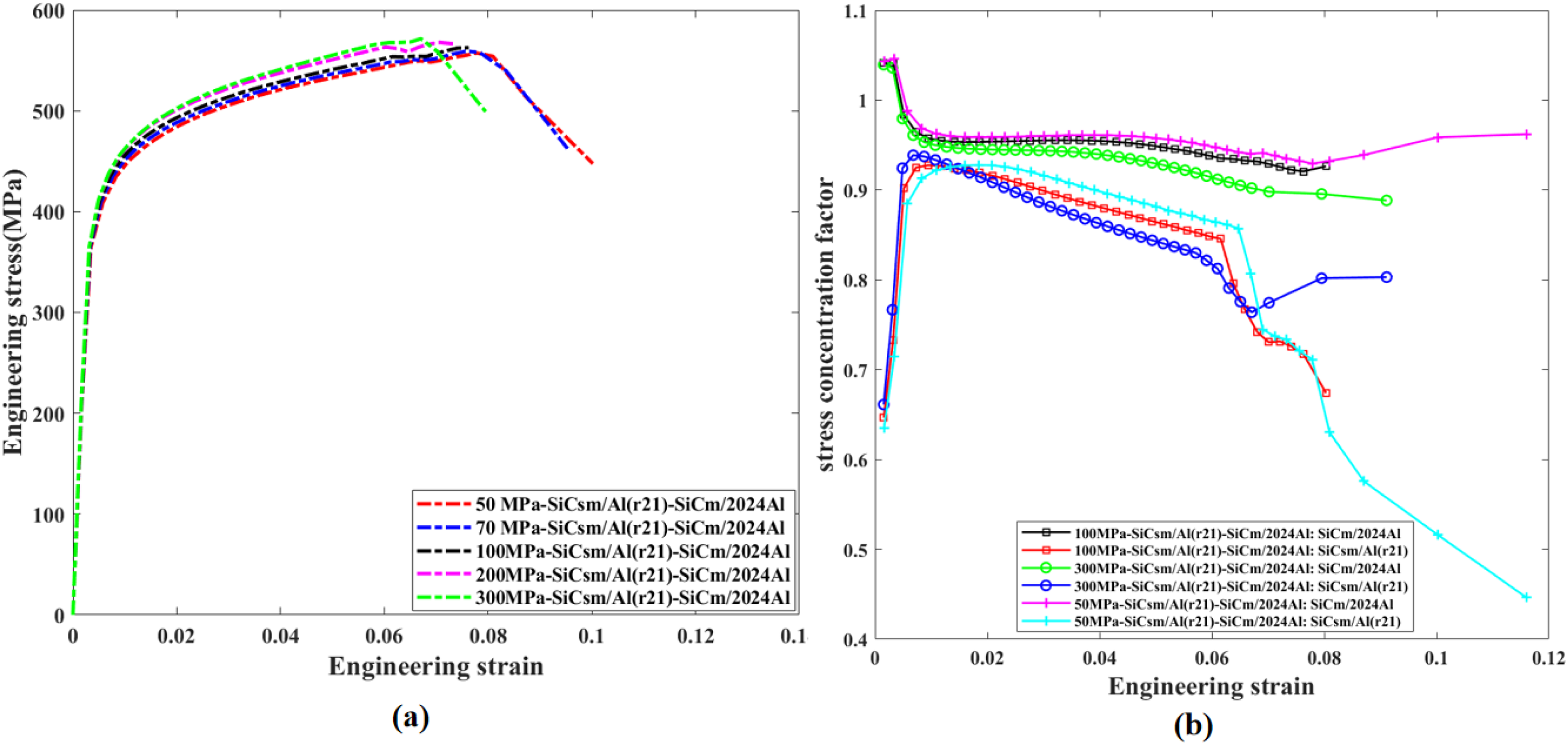
(a) The equivalent stress–strain curves, (b) stress concentration factors of SiCsm/Al(r21)-SiCm/2024Al composites with layer interface strengths of 50 MPa, 70 MPa, 100 MPa, 200 MPa, and 300 MPa. SiCm, micron silicon carbide; Al, aluminum.
Figure 19 shows the strain contour plot of SiCsm/Al(r21)-SiCm/2024Al composites with layer interface strengths of 50 MPa, 100 MPa, and 300 MPa. Comparing Figure 19 (a-3), (b-3), and (c-3), it can be seen that when the layer interface strength value is relatively weak at 50 MPa, the layer interface between elements is more prone to debonding, causing a large number of micro-cracks in the composites and alleviating local stress concentration. In addition, introducing weak layer interfaces can introduce low-energy paths for crack propagation. When the main crack propagates forward to the weak layer interface under load, there are a large number of defects at the weak layer interface, leading to layer interface delamination, which plays a toughening role.

The strain contour plots of SiCsm/Al(r21)-SiCm/2024Al composites with layer interface strengths of 50 MPa, 100 MPa, and 300 MPa. SiCsm, submicron silicon carbide; SiCm, micron silicon carbide; Al, aluminum.
Configuration and layer-interface-performance design of composites with excellent strength–toughness performance
In Sections The effect of element size on the strength–toughness of composites and The effect of layer-interface-performance between elements on the strength–toughness of composites, we analyzed the tensile fracture mechanism and explored the influence of configuration parameters and layer interface strength on the mechanical properties of layered configuration composites. Through the collaborative design of configuration parameters and layer interface strength, as shown in Figure 20, compared with SiCsm/Al(r21)-SiCm/2024Al with layer interface strength of 100 MPa, SiCsm/Al(r24)-SiCm/2024Al with layer interface strength of 150 MPa has better fracture toughness without weakening material strength. Table 5 compares the tensile mechanical properties of these two composites. The elongation of SiCsm/Al(r24)-SiCm/2024Al with layer interface strength of 150 MPa is 12.52%, which is 55.92% higher than that of the SiCsm/Al(r21)-SiCm/2024Al with layer interface strength of 100 MPa.
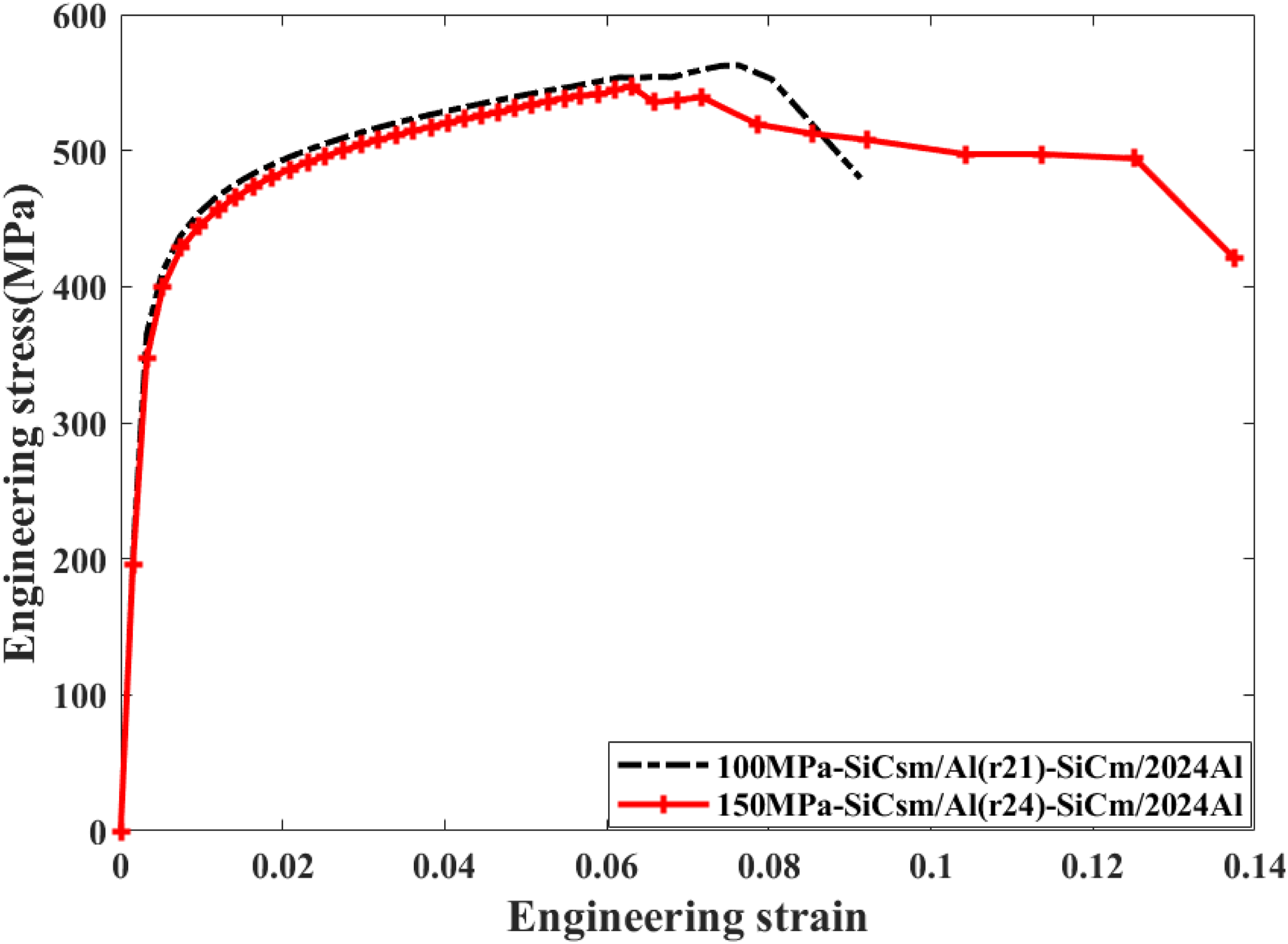
The equivalent stress–strain curves of SiCsm/Al(r21)-SiCm/2024Al with a layer interface strength of 100 MPa and SiCsm/Al(r24)-SiCm/2024Al with a layer interface strength of 150 MPa. SiCsm, submicron silicon carbide; SiCm, micron silicon carbide; Al, aluminum.
The tensile mechanical properties of two composites.
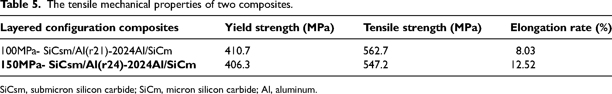
SiCsm, submicron silicon carbide; SiCm, micron silicon carbide; Al, aluminum.
The fracture morphology is taken as Figure 21, and it can also be seen that SiCsm/Al(r24)-SiCm/2024Al with layer interface strength of 150 MPa undergoes a long crack propagation and complex fracture process during tensile fracture.
The (a) fractography and (b) profile fracture surface of SiCsm/Al(r24)-SiCm/2024Al with layer interface strength of 150 MPa. SiCsm, submicron silicon carbide; SiCm, micron silicon carbide; Al, aluminum.
Conclusion
In this study, a multi-scale numerical simulation method is used to analyze the mechanical behavior of novel SiCsm/Al-SiCm/2024Al composites with a ductile–ductile-layered configuration prepared experimentally. An optimization design method of synergizing microscopic mechanical properties with structural configuration has been developed for the strengthening–toughening trade-off of ductile–ductile-layered configuration composites.
The microstructural characteristics of the composites are restored by establishing multi-scale RVEs at microscopic and mesoscopic scales, and the progressive damage analysis of the composites under tensile load is realized, which is in good agreement with the experimental test results. To study the strengthening–toughening mechanism of how the microstructural configuration and layer-interface property between the SiCsm/Al element and the SiCm/2024Al element influence the mechanical behavior of the composites, a series of FE models is established of SiCsm/Al-SiCm/2024Al composites whose mechanical properties are calculated. The analysis shows the following results:
Comparing the stress–strain curves and stress concentration factor curves of the SiCsm/Al-SiCm/2024Al composites, the strengthening–toughening is mainly affected by SiCsm/Al. When the size of SiCsm/Al element of the SiCsm/Al-SiCm/2024Al composites is too large, the fracture toughness will be reduced greatly, while the SiCsm/Al element that is too small will lead to stress concentration, leading to premature yielding of the composites and reducing its strength. By analyzing progressive damage contour plots, it is found that there are six types of damage modes in the SiCsm/Al-SiCm/2024Al composites during tensile fracture, which lead to multiple crack forms including ductile cracks of the SiCsm/Al layer, tunnel cracks of the SiCsm/Al layer, ductile cracks of the SiCm/2024Al layer, and delamination cracks between the SiCsm/Al layer and the SiCm/2024Al layer. The main factors for strengthening are the strong layer interface and the larger size of the SiCsm/Al element, while the main factors for toughening are, among others, the appropriate size ratio of the SiCsm/Al element and the SiCm/2024Al element, the rich crack form, and the weaker layer interface.
Therefore, based on the analysis results of the strength–toughness influencing factors of composite properties, the strengthening–toughening trade-off of the SiCsm/Al-SiCm/2024Al composites is realized through the collaborative design of configuration parameters and layer interface strength. And the layered configuration composites of SiCsm/Al(r24)-SiCm/2024Al with a layer interface strength of 150 MPa, which has better fracture toughness without weakening material strength. Therefore, to improve the strength of the composites, it is necessary to ensure a strong layer interface and design a larger size of SiCsm/Al element in the experimental preparation process. At the same time, to improve the toughness of the composites, an appropriate size ratio of the SiCsm/Al element and the SiCm/2024Al element should be adopted (the size of the SiCsm/Al element in this paper is designed to be 48μm in diameter), and the strength of the layer interface is not too high.
However, in this study, the modeling of interfaces is relatively simple and idealized, and the influence of strain gradient plasticity on heterogeneous interfaces cannot be considered, and how the SiCm/2024Al element affects the strength and toughness of composites has not yet been thoroughly explored. In future work, we will carry out the following aspects: (1) establish a constitutive model of the metal matrix considering the strain gradient, and (2) establish a configuration design method based on the size ratio of the element and the strength ratio of the interface to the element.
Footnotes
Declaration of conflicting interests
The authors declared no potential conflicts of interest with respect to the research, authorship, and/or publication of this article.
Funding
The authors disclosed receipt of the following financial support for the research, authorship, and/or publication of this article: This work was supported by the National Natural Science Foundation of China, (grant number 52192595).