Calculations have been conducted to show that it may be feasible to enhance the tetragonality ( ratio) of tetrataenite () by charging it with hydrogen, a process that can be achieved at ambient temperature, well below the ordering temperature of the FeNi compound. Although the saturation magnetisation is slightly compromised, the magnetocrystalline anisotropy should increase significantly. It is now worth doing experiments to establish or disprove the results, because the energy of inserting a single hydrogen atom into the location that enhances tetragonality is slightly greater than that in a sub-optimal site in the context of increasing the ratio. Changes in tetragonality as a function of the location of the hydrogen atom can be explained in terms of the relative strengths of the Fe-H and Ni-H bonds.
The metal-rich phases found in iron, stony iron, and as inclusions in chondrite meteorites, consist of (A2; ), (A1; ), (L1; ) and (L1; ).1,2 In the absence of impacts, the meteorites cool from the red-hot state ( K) at 1-1000 K per million years.3 All the phases are ferromagnetic below their respective Curie temperatures, but tetrataenite is particularly interesting because of its high magnetocrystalline anisotropy.4 High magnetocrysalline anisotropy can primarily be considered to enhance coercivity, which also is influenced by the microstructure5. In the perfectly ordered state, the magnetic moment is 1.625 , with iron contributing 2.6–2.63 and nickel 0.6–0.62 .6,7 The moment per iron atom is greater than that found for any of the three common allotropic forms of pure iron [pp.30–39, Bhadeshia8], Steinle-Neumann et al.9 The first-principles calculated (0 K) direction of magnetisation of a single crystal of tetrataenite is along the four-fold axis of symmetry [001].6
Tetrataenite has the chemical composition close to FeNi and orders at C10,11 where diffusion is imperceptibly slow. It is therefore impossible to replicate the compound found in meteorites, on Earth, though valiant efforts have produced samples by difficult means and in an imperfectly ordered state in the form of minute particles.12,13 It is likely, however, that progress may be made in the future so that permanent magnets can be made that don’t quite compete with rare-earth varieties but have a favourable position in the cost versus plot.14
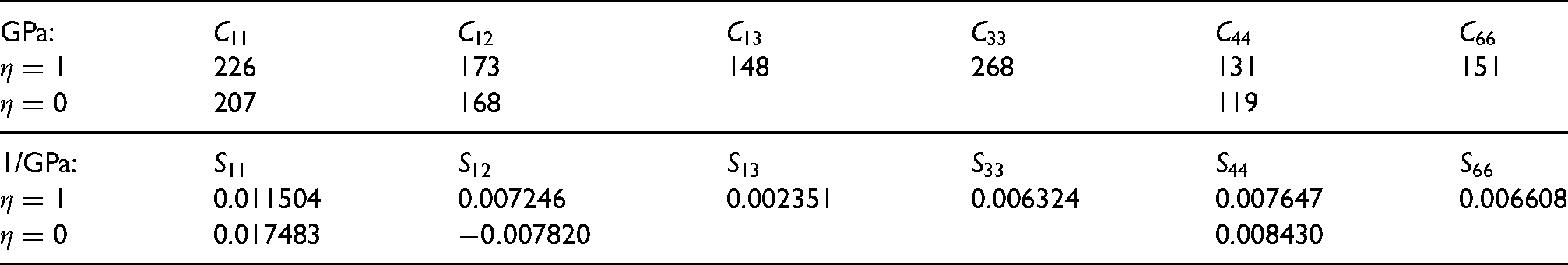
A low-symmetry crystal structure that is ferromagnetic will tend to have greater magnetocrystalline anisotropy. The tetragonaility of as a face-centred tetragonal structure is rather small, with lattice parameters of Å and Å as measured using synchrotron X-rays.15,16 However, the primitive cell of is body-centred tetragonal, with and , resulting in a large magnetocrystalline anisotropy.15 If something could be done to enhance the tetragonality, that would inevitably lead to a greater magnetocrystalline anisotropy. The best way to do this might be to introduce small but misfitting-atoms at , into the irregular-octahedral interstices that are slightly longer along the -axis.1 Single-crystal moduli () have been calculated as a function of the long-range order parameter ,16 from which the compliances have been calculated here in a manner consistent with the tetragonal symmetry, as in Ballato:17
GPa:
226
173
148
268
131
151
207
168
119
1/GPa:
0.011504
0.007246
0.002351
0.006324
0.007647
0.006608
0.017483
0.008430
Using the data, it is straightforward to show that the single crystal is much stiffer along [001] than along .2 Substitution of misfitting atoms into the octahedral interstices should then lead to a reduction in the ratio. This is confirmed by first-principles calculations of tetrataenite that has been nitrided,18 perhaps leading to the general conclusion that any small atom that causes dilation would reduce the tetragonality. An elasticity analysis does not account for subtleties based on the local environment around the any interstitial atoms in an ordered as discussed below in the context of hydrogen alloying.
The alloying of tetrataenite with hydrogen has never previously been examined, but the huge advantage is that it can be incorporated into by electrochemical charging under ambient conditions, i.e. well below the ordering temperature. Hydrogen is known to expand ordinary austenite,19 i.e., it’s effective size is greater than that of the interstice, and therefore might be expected to reduce the ratio given that the parameter is smaller than . The conclusion reached on the basis of that the tetragonality of should decrease when hydrogen is introduced into the lattice neglects H-metal interactions that are dependent on the specific environment around each hydrogen atom, which will not be identical for similarly-shaped interstices in -. Assuming that there is an iron atom at the origin of the unit cell, an octahedral interstice at has nickel atoms at , whereas the corresponding interstice at has iron atoms at and . This kind of subtlety is absent in the elastic analysis presented above. It is necessary therefore to conduct first-principles calculations to study changes in that could in principle promote magnetocrystalline anisotropy. Insertion of hydrogen into tetrahedral interstices, which are less favoured for hydrogen occupation in paramagnetic austenite in pure iron,20 has also been examined out of interest.
Calculations
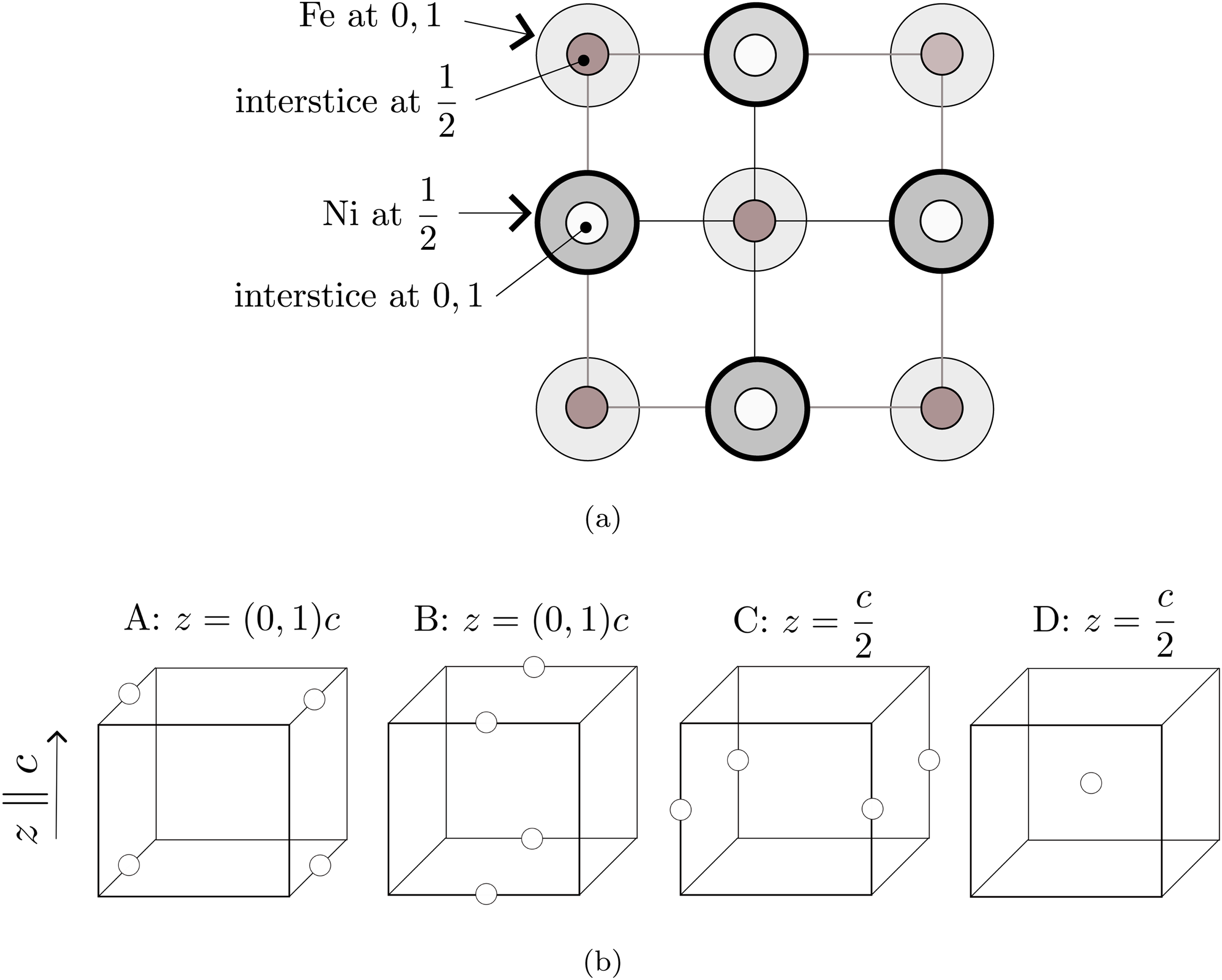
First-principles calculations were conducted using the Vienna Ab-initio Simulation Package21,22 with the projector augmented-wave formalism. The () was implemented using a conventional unit cell with two Fe atoms and two Ni atoms, as shown in Figure 1 which includes the locations of the octahedral-interstices. Unlike a disordered structure, the two kinds of octahedral interstices at and are not equivalent. Those at are surrounded on the plane normal to by four near-neighbour iron atoms, whereas those at have four near-neighbour nickel atoms. The two sets of interstices are, therefore, not equivalent, and the consequences will become apparent in the calculation results. The tetrahedral interstices are located at all equivalent [1/4,1/4,1/4] positions, with each such interstice surrounded by two Fe atoms and two Ni atoms.
(a) Projection of the conventional tetragonal unit-cell of FeNi containing two Fe and two Ni atoms on to the (100) plane, with the fractional coordinates along the [001] -axis marked. The origin of the cell-axes is set to an iron atom. The small circles represent the octahedral interstices. (b) Configurations of octahedral interstices with fractional coordinates indicated; metal atoms omitted for clarity. If each configuration is occupied completely by hydrogen atoms, the net contribution to the unit cell would be one hydrogen atom because the sites may be shared with adjacent cells.
The total energies were obtained using the Perdew-Burke-Ernzerhof realisation of the generalised gradient approximation for the exchange-correlation potential.23 A plane-wave basis set with a cut-off energy of 720 eV was used in all calculations. Integrations over the three-dimensional Brillouin zone were performed using the tetrahedron method over an Monkhorst-Pack mesh for the conventional unit cell, and the total energy is converged to an accuracy of eV. All structures were assumed to be in the ferromagnetic state. The initial lattice parameters were adapted from experimental values ( Å, Å).24 Internal atomic relaxation and geometry optimisation were achieved when the change in total energy between two ionic steps was smaller than eV atom−1. Spin polarisation was considered for all calculations, and the convergence of these computational parameters was checked carefully. All thermal contributions were neglected in the present calculations. The formation energy of each structure was calculated using the following formula:
where and are the total energies of FeNi + H and FeNi structure, respectively. is the total energy of hydrogen in its gaseous state.
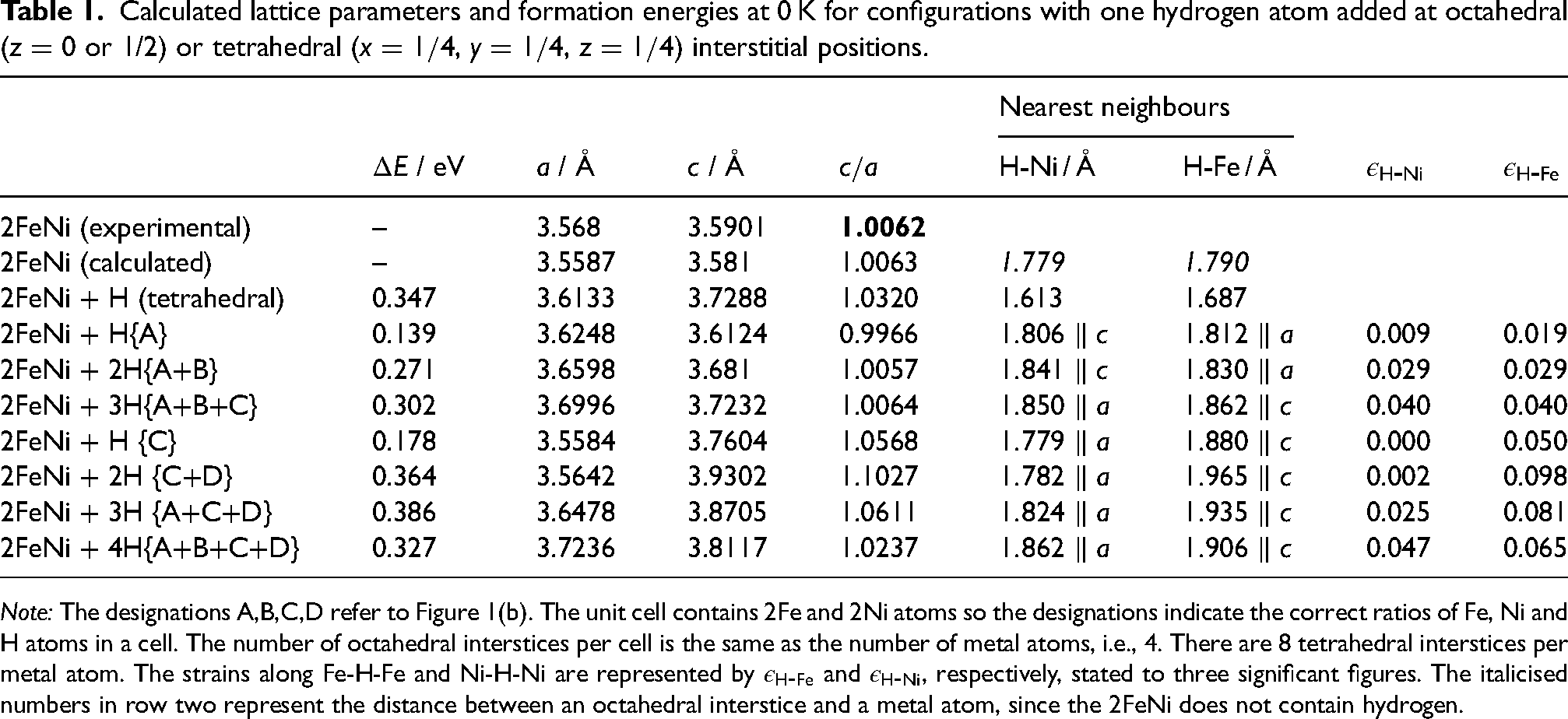
Table 1 summarises the changes in lattice parameters and formation energies from the first-principles calculations. For FeNi, the calculated lattice parameters (representing 0 K) are about 0.2% smaller than the experimentally measured ambient-temperature values in both the and directions. The ratio closely matches the experimental values.
Calculated lattice parameters and formation energies at 0 K for configurations with one hydrogen atom added at octahedral ( or 1/2) or tetrahedral (, , ) interstitial positions.
Nearest neighbours
/ eV
/ Å
/ Å
H-Ni / Å
H-Fe / Å
2FeNi (experimental)
–
3.568
3.5901
1.0062
2FeNi (calculated)
–
3.5587
3.581
1.0063
1.779
1.790
2FeNi + H (tetrahedral)
0.347
3.6133
3.7288
1.0320
1.613
1.687
2FeNi + H{A}
0.139
3.6248
3.6124
0.9966
0.009
0.019
2FeNi + 2H{A+B}
0.271
3.6598
3.681
1.0057
0.029
0.029
2FeNi + 3H{A+B+C}
0.302
3.6996
3.7232
1.0064
0.040
0.040
2FeNi + H {C}
0.178
3.5584
3.7604
1.0568
0.000
0.050
2FeNi + 2H {C+D}
0.364
3.5642
3.9302
1.1027
0.002
0.098
2FeNi + 3H {A+C+D}
0.386
3.6478
3.8705
1.0611
0.025
0.081
2FeNi + 4H{A+B+C+D}
0.327
3.7236
3.8117
1.0237
0.047
0.065
Note: The designations A,B,C,D refer to Figure 1(b). The unit cell contains 2Fe and 2Ni atoms so the designations indicate the correct ratios of Fe, Ni and H atoms in a cell. The number of octahedral interstices per cell is the same as the number of metal atoms, i.e., 4. There are 8 tetrahedral interstices per metal atom. The strains along Fe-H-Fe and Ni-H-Ni are represented by and , respectively, stated to three significant figures. The italicised numbers in row two represent the distance between an octahedral interstice and a metal atom, since the 2FeNi does not contain hydrogen.
The location of the hydrogen atoms for the purposes of calculation are designated A, B, C and D in Figure 1(b), terminology consistently used in Table 1 and throughout to express the variety of configurations of octahedral interstices studied, together with their outcomes.
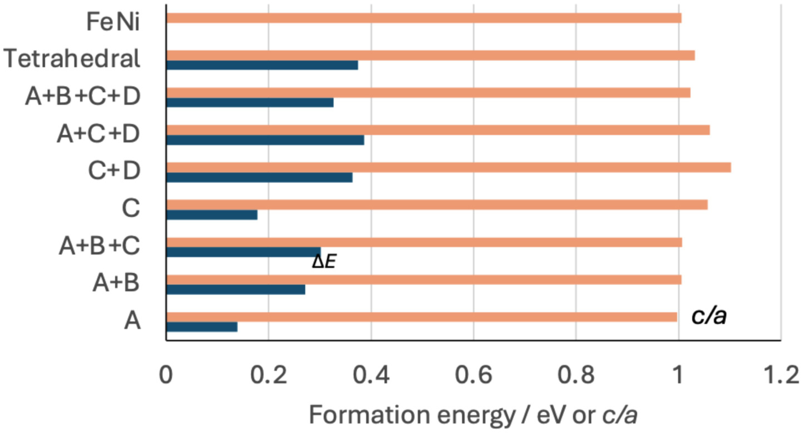
The insertion of a single hydrogen atom at a mole fraction , in octahedral interstices in a manner consistent with either the configuration A or B yields the most favoured location in terms of . The ratio is reduced because the positive strain along Fe-H-Fe which is parallel to the parameter is much greater than along Ni-H-Ni which is parallel to the -axis.
The is greater when both A and B are occupied with . The ratio is only slightly smaller than for pure FeNi because along the Ni-H-Ni orientation becomes similar to (Table 1, Figure 2). It follows that placing hydrogen atoms at the equivalent A or B sites, in any combination, does not increase the tetragonality of . This is consistent with the Fe-H-Fe chains parallel to the -axes on the (100) planes being more compliant to the insertion of hydrogen at . Adding a third H-atom (A+B+C) uniformly expands the lattice but with only a small increase in .
Changes in formation energy and ratio from first-principles calculations as a function of the location and concentration of hydrogen, with the latter quantities defined by the designations A,B,C,D in Figure 1(b) in the case of the octahedral interstices.
Placing a single hydrogen atom in an octahedral interstice at ‘C’ (or its equivalent ‘D’) leads to a dramatic increase in tetragonality, with eV being slightly larger than the most favourable location ‘A’ (eV), Table 1. At those locations, the Fe-H-Fe chains are parallel to the -axis with , leading to the increased ratio. Two hydrogen atoms at C+D maximises the tetragonality. The general conclusion from all the data presented in Figure 2 is that locating hydrogen atoms in configurations C,D where it lies in the nickel-atom planes, maximises tetragonality, with hydrogen concentrations in excess of causing reductions in because atoms would necessarily have to locate on the A,B sites.
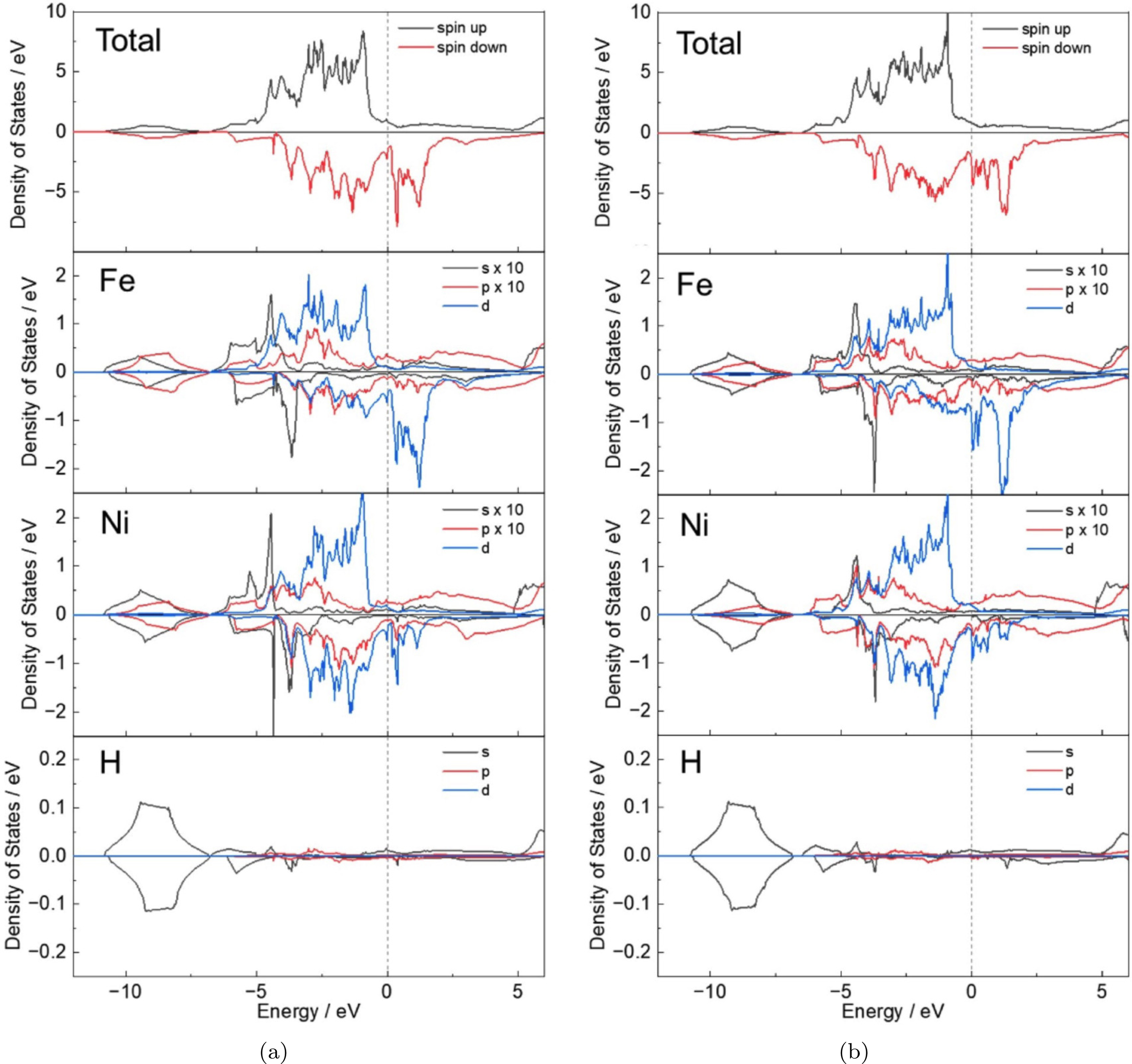
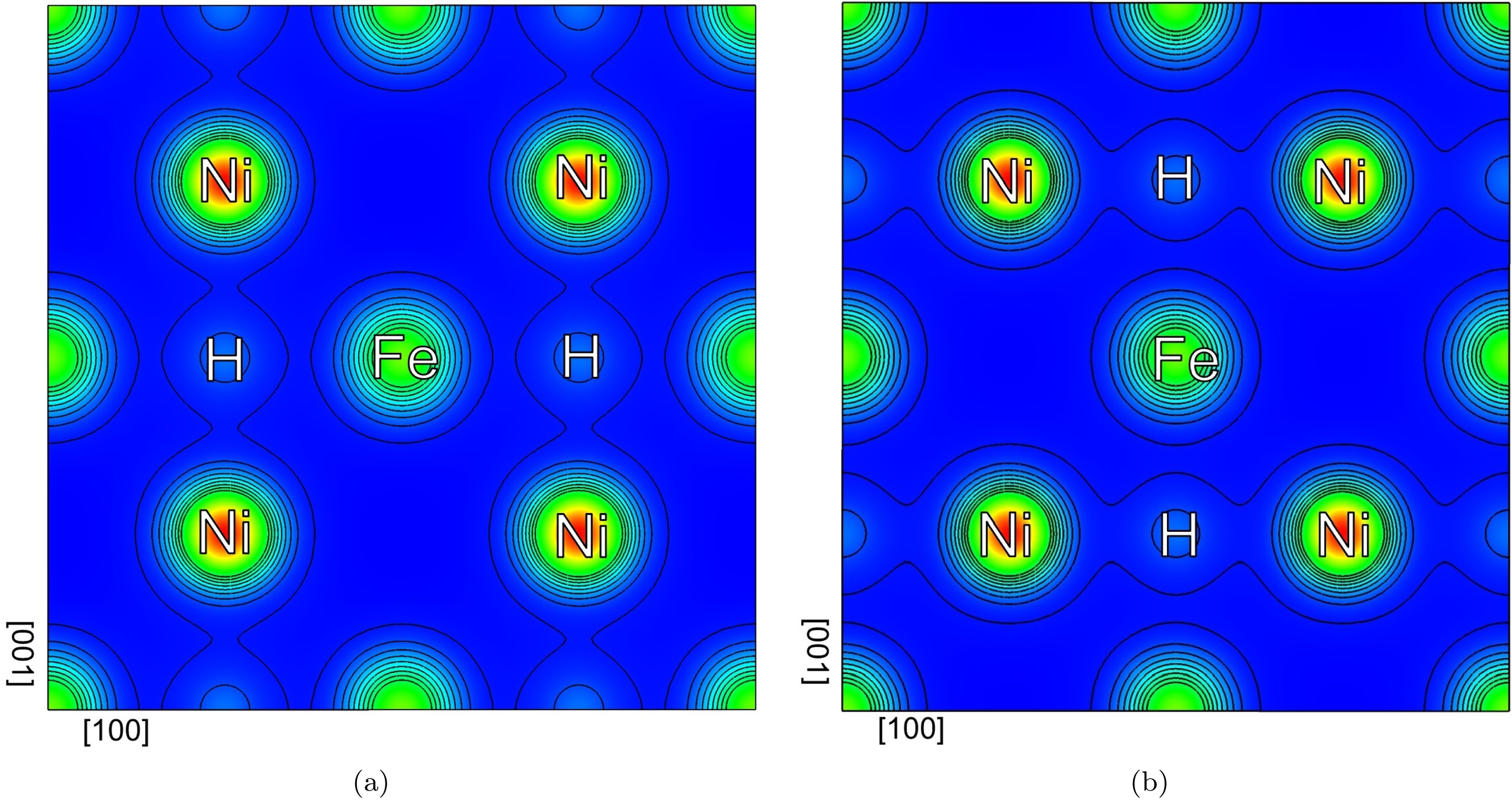
It is useful to understand why the Fe-H-Fe chains are more flexible relative to Ni-H-Ni. Figure 3 shows the calculated total and partial local density of states (DOS) for the hydrogen atom, and the nearest Fe and Ni atoms. At both configurations, the H- orbital commonly overlaps with the and states of the nearest Fe and Ni atoms in the energy range eV to eV. In the Fe-H bonding, the contribution of the -state is relatively large, while in the Ni-H bonding, the -state at lower energy levels plays a more significant role. Moreover, the peak height of the DOS for Ni-H bonding is greater than for the Fe-H bonding, and the energy value is lower, indicating a stronger bond. This is confirmed by the maps in Figure 4 which show the charge density contour plots in the plane normal to the -axis intersecting the Fe, Ni, and H atoms for configurations ‘A’ and ‘C’. In both cases, the charge density of H overlaps more with Ni than with Fe, and consequently, the chain of atoms in the Fe-H-Fe configuration is extended to a significantly larger spacing compared to the Ni-H-Ni chain on the (002) plane.
The calculated total and partial local density of states for Fe, Ni and H on configurations (a) ‘A’ and (b) ‘C’. Fe and Ni refer to the atoms in the nearest vicinity to H atoms. The spin down DOS values are factored by , and the Fermi levels () are set to zero. For comparison, the density corresponding to the and -states of Fe and Ni atoms was factored by 10.
Charge density contour plots in the plane normal to the -axis, cutting the Fe, Ni and H atoms for configurations (a) ‘A’ and (b) ‘C’. The horizontal axis represents [100] direction, while the vertical axis is parallel to [001].
It is noted that insertion of a single H-atom into a tetrahedral interstice leads to the largest for and further calculations for larger concentrations, not listed here, do not improve the situation. Tetrahedral interstices are therefore not considered further.
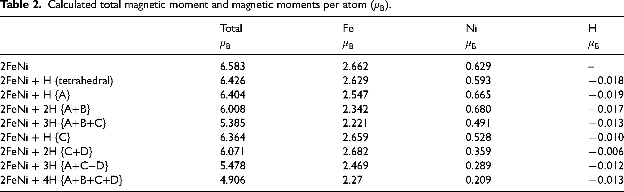
The presence of hydrogen in does reduce the net magnetic moment per atom which in turn should reduce the saturation magnetisation of the material (Table 2). However, the reduction of total for configurations ‘C’ and ‘C+D’ which have large ratios might be tolerated if the magnetocrystalline anisotropy is enhanced to produce more-permanent magnets.
Calculated total magnetic moment and magnetic moments per atom ().
Total
Fe
Ni
H
2FeNi
6.583
2.662
0.629
–
2FeNi + H (tetrahedral)
6.426
2.629
0.593
2FeNi + H {A}
6.404
2.547
0.665
2FeNi + 2H {A+B}
6.008
2.342
0.680
2FeNi + 3H {A+B+C}
5.385
2.221
0.491
2FeNi + H {C}
6.364
2.659
0.528
2FeNi + 2H {C+D}
6.071
2.682
0.359
2FeNi + 3H {A+C+D}
5.478
2.469
0.289
2FeNi + 4H {A+B+C+D}
4.906
2.27
0.209
Several studies in the past have investigated the magnetocrystalline anisotropy energy (MAE) in tetrataenite using both first-principles calculations and experimental methods.25–27 Defining the energy difference , where and are the total energies, including spin-orbit coupling, we obtained MAE with magnetisation aligned along the [100] and [001] directions, respectively. This calculation is performed for both the structure without hydrogen and in the of hydrogen in the ‘A’ and ‘C’ configurations, using optimised lattice parameters.
Since the magnetic easy axis of tetrataenite is [001], the MAE should be positive.25,28 For FeNi without hydrogen, it is calculated to be 91.1 eV/f.u., consistent 76-128 eV/f.u. reported in previous studies.28,29 The corresponding estimates for configurations ‘A’ and ‘C’ are 221.0 and 133.9 eV/f.u., respectively, both significantly greater than without hydrogen, suggesting that the presence of hydrogen enhance the magnetocrystalline anisotropy in both configurations.
Conclusions
It is possible that the alloying of tetrataenite with hydrogen, for example by electrochemical charging, can lead to significant increases in the tetragonality of its unit cell, and hence in its magnetocrystalline anisotropy and coercivity. The optimum location of the hydrogen atoms in this context is in the octahedral interstices at where it is surrounded on the plane (002) by four near neighbour nickel atoms. This is because the chain of atoms Fe-H-Fe normal to that plane (parallel to ) is extended to a significantly larger spacing than any Ni-H-Ni chain on the plane (002) because the Ni-H bonding is significantly stronger than Fe-H bonds. The ratio and magnetocrystalline anisotropy therefore increases though the saturation magnetisation is reduced by a small amount.
Although the energy for the introduction of a single hydrogen atom on (002) is about 28% greater than on (001), it still is reasonably small (0.178) so it may be feasible for hydrogen atoms to reside there during electrochemical-charging.
Insertion of hydrogen into the octahedral sites on (001) where it is surrounded by iron atoms as nearest neighbours is not useful in altering since the expansion of the Fe-H-Fe chains on that plane leads to increases in the -parameter. Nevertheless, the MAE calculation indicate an enhancement in magnetocrystalline anisotropy.
Footnotes
Acknowledgement
This work was funded by the Fundamental R&D Program of the Korea Institute of Materials Science (KIMS), Grant No. PNK9630. This work was also supported by the Industrial Strategic Technology Development Program (No. 20010942) and Nuclear Power Plant Decommissioning Competitiveness Enhancement Technology Development Project (RS-2023-00234190) funded by the Ministry of Trade, Industry & Energy (MOTIE, Korea).
Declaration of conflicting interests
The author(s) declared no potential conflicts of interest with respect to the research, authorship, and/or publication of this article.
Funding
The author(s) disclosed receipt of the following financial support for the research, authorship, and/or publication of this article.
Notes
References
1.
AlbertsenJKnudsenJJensenG. Structure of taenite in two iron meteorites. Nature1978; 273: 453–454.
2.
ClarkeRSScottER. Tetrataenite—ordered FeNi, a new mineral in meteorites. Am Mineral1980; 65: 624–630.
3.
LyonsRJBowlingTJCieslaFJ, et al. The effects of impacts on the cooling rates of iron meteorites. Meteorit Planet Sci2019; 54: 1604–1618.
4.
PaulevéJChamberodAKrebsK, et al. Magnetization curves of Fe–Ni (50–50) single crystals ordered by neutron irradiation with an applied magnetic field. J Appl Phys1968; 39: 989–990.
5.
CoeyJM. Magnetism and magnetic materials. Cambridge: Cambridge university press, 2010.
6.
GuenzburgerDTerraJ. Theoretical study of magnetism and Mössbauer hyperfine interactions in ordered FeNi and disordered fcc Fe-rich Fe–Ni alloys. Phys Rev B - Condens Matter Mater Phys2005; 72: 024408.
7.
LewisLHMubarokAPoirierE, et al. Inspired by nature: investigating tetrataenite for permanent magnet applications. J Phys Condens Matter2014; 26: 064213.
8.
BhadeshiaHKDH. Theory of transformations in steels. Abingdon: CRC Press, 2021.
AbduYEricssonTAnnerstenH, et al. Mössbauer studies on the metallic phases of Al Kidirate and New Haifa meteorites. In: Hyperfine interactions (C) proceedings of the international conference on the applications of the Mössbauer effect, (ICAME 2001), 2–7 September 20011, 2002, pp.375–378. Oxford, UK: Springer.
25.
IzardarAEdererC. Interplay between chemical order and magnetic properties in L10 FeNi (tetrataenite): a first-principles study. Phys Rev Mater2020; 4: 054418.
26.
LewisLHPinkertonFEBordeauxN, et al. De magnete et meteorite: cosmically motivated materials. IEEE Magn Lett2014; 5: 1–4.
27.
EdströmAChicoJJakobssonA, et al. Electronic structure and magnetic properties of L10 binary alloys. Phys Rev B2014; 90: 014402.
28.
NéelLPauleveJPauthenetR, et al. Magnetic properties of an iron—Nickel single crystal ordered by neutron bombardment. J Appl Phys1964; 35: 873–876.
29.
KojimaTOgiwaraMMizuguchiM, et al. Fe–Ni composition dependence of magnetic anisotropy in artificially fabricated L10-ordered FeNi films. J Phys Condens Matter2014; 26: 064207.
30.
GorodtsovVATkachenkoVGLisovenkoDS. Extreme values of Young’s modulus of tetragonal crystals. Mech Mater2021; 154: 103724.