
Abstract
Aluminum foams excel as versatile materials by combining porous structures with aluminum alloys properties. The infiltration method provides precise control over pore size and distribution, but depends on space holder particles (SHP) characteristics. This study examines the influence of SHP morphology on the structural and mechanical properties of infiltrated aluminum foams. Al-319 alloy was used with NaCl SHPs (∼5 mm of equivalent diameter) with three morphologies: spherical, ellipsoidal, and irregular. Structural characterization included density measurements, image analysis, and computed tomography. Uniaxial compression tests revealed that foams with granulated pores had the lowest properties (E = 1.15 GPa, σpt = 13.19 MPa, Eabs = 7.51 MJ/m³), while spherical pores maximized energy absorption (10 MJ/m³) due to improved load distribution.
Keywords
Introduction
During the last years, metallic foams have gained recognition from the scientific community as versatile materials with unique properties obtained from the combination of porous structures and metallic matrices. Some examples of these properties are high stiffness, low specific weight, high surface area, and good thermal and electrical conductivity, making them suitable for a multitude of applications such as blast and energy absorption, structural lightening, fire resistance, thermal insulation, vibration and sound damping, among others.1–3 Scientific research has led to the creation and development of a wide variety of manufacturing processes for metallic foams, following different methods for generating a pore network within the solid metal matrix. As stated by Banhart et al., 1 these manufacturing methods can be classified according to the physical state of the base alloy during the phase of pore formation, originating four families: liquid metal, solid metal, metal ions, and metal vapor. Among the different manufacturing methods available, infiltration over Space Holder Particles (SHP), belonging to the liquid metal family, excels for allowing to obtain interconnected regular porosity. Besides, it offers good control over the size, quantity, and morphology of the pore phase and has a low cost since SHP materials tend to be cheap. 4 This method consists of the use of a volume of particles that act as a preform, temporarily retaining the space that subsequently will become the pore phase. A composite is obtained by casting a molten alloy over the particles, gradually filling the empty space between them. Once infiltration and solidification are completed, the SHPs are eliminated by different means, commonly by dissolution. It is noteworthy that a variation of this method replaces the molten alloy with a powdered alloy, which is compacted along with SHPs and subsequently subjected to a sintering process to form the metal matrix.1,5,6 Aluminum alloys are particularly suitable for the infiltration method due to their low melting point and good castability, especially those with high silicon contents, as they exhibit high fluidity, which is highly desirable to achieve complete and homogeneous infiltration.
Although some properties of aluminum foams are retained from the base alloy such as melting point and specific heat, mechanical properties mainly depend on the porous structure. 7 In the case of aluminum foams manufactured by infiltration, the structural properties are strongly related to SHP characteristics, some of which directly depend on the space holders, since these determine structural properties such as shape, size, and number of pores. Besides, other structural properties are related to SHP packing density, e.g., total porosity and cell wall thickness. The objective of this work is to analyze the effect of different pore morphologies on the mechanical properties of aluminum foams by exploring the use of three different types of SHPs (irregular grains, spherical and ellipsoidal). The motivation for our research is based on the fact that as shown by different works,8–11 packing density of a particulate volume is highly affected by factors associated with individual particle morphology such as aspect ratio, sphericity, and, coordination number. With the aim of achieving a better understanding of the effect of these morphological parameters on both the structural and mechanical properties, this work used 3D models obtained through Computed Tomography (CT) scans, allowing better visualization of the porous phase and facilitating the characterization of the different structural features and their correlation with the mechanical properties of the foams. CT has demonstrated to be an efficient method for aluminum foams structural analysis due to its high precision in recreating complex pore structures. This has been proven in research works such as those by Ghazi et al. 12 and Guo et al. 13 where CT is used successfully to recreate closed cell models of aluminum foams. Similarly, Mauko et al. 14 have proven the effectiveness of CT for modeling and analysis of open cell aluminum foams. In addition to this, compressive mechanical tests were conducted to measure the mechanical properties of aluminum foams. Subsequent analysis of the correlation between mechanical performance and pore structural characteristics was carried out.
Even though sodium chloride (NaCl) irregular grains are the most commonly used SHP, studies on aluminum foams using alternative morphologies have been reported in previous research works. However, these are usually limited to the use of powder metallurgy route15–17 since alternative morphologies are commonly found in materials with lower melting points than NaCl, such as carbamide. The use of infiltration method with alternative NaCl morphologies, mainly spherical, has been achieved successfully in recent research, such as the works by Finkelstein et al. 18 and by Jinnapat & Kennedy. 19 Nevertheless, in both cases, the aim of research was not comparison with other morphologies. A comparative study between irregular and spherical SHP was successfully conducted by Goodall et al. 20 who fabricated NaCl beads for aluminum foam manufacturing. Nonetheless, this research was limited to micrometric SHP sizes and only included irregular and spherical morphologies. Then, the aspects discussed above distinguish this research and constitute its novelty on the topic.
Materials and methods
Space holder particles
The obtention of the different SHPs was the first step for aluminum foams manufacturing. As previously mentioned, three SHP morphologies were proposed: irregular grains, spherical and ellipsoidal. Irregular grain-shaped SHPs were obtained directly from common commercial salt grains (NaCl), which were manually sieved using 6 and 5 mm sifters. On the other hand, spherical and ellipsoidal particles had to be manufactured due to the unavailability of these morphologies. For this purpose, a supersaturated solution was prepared using powdered NaCl (≈0.7 mm) as the solute and water as the solvent in a proportion of 2:1 in volume ratio. After this, the supersaturated solution was manually poured in flexible silicon molds with spherical and elliptical cells as shown in Figure 1, whose fabrication will be further commented. To fully consolidate the SHPs, a heat treatment was conducted in a conventional electric oven at 150°C for 30 min., this helps to eliminate water and promote coalescence between powdered NaCl, obtaining a solid particle that can be easily extracted from the molds.
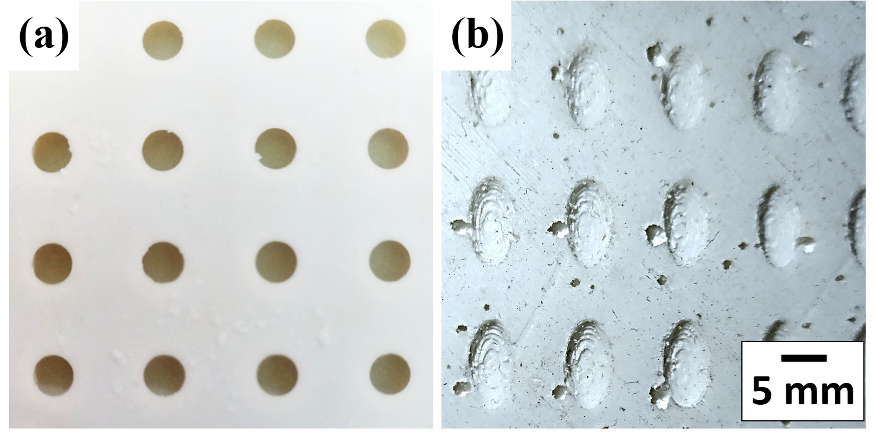
Molds used for SHP manufacturing: (a) Spherical shape, (b) Ellipsoidal shape.
It is worth mentioning that, although ellipsoidal and spherical particles were manufactured using silicon molds, only the spherical ones were commercially available, whereas the ellipsoidal cell molds had to be custom-made. This was done by designing a pattern mold in the CAD Software Design Modeller® from ANSYS ver. 19.0, shown in Figure 2(a) and (b). The mold was later 3D printed in polylactic acid (PLA) using a high precision K3Ps equipment from the brand KINGROON®, as observed in Figure 2(c) and (d). The molds were composed by two parts as it can be observed in Figure 2(a)–(d), the top part has the ellipsoidal particle shape and the bottom part has ellipsoidal cavities. Once the molds were 3D printed, the bottom part was filled with the prepared silicone and pressed manually with the top part to form the silicone mold, once formed the mold was dried for 3 h. The silicone was acquired from the Brand “Silicones de Mexico” with a silicone-diluent proportion of 2:1 and using catalyst concentration of 2% wt.
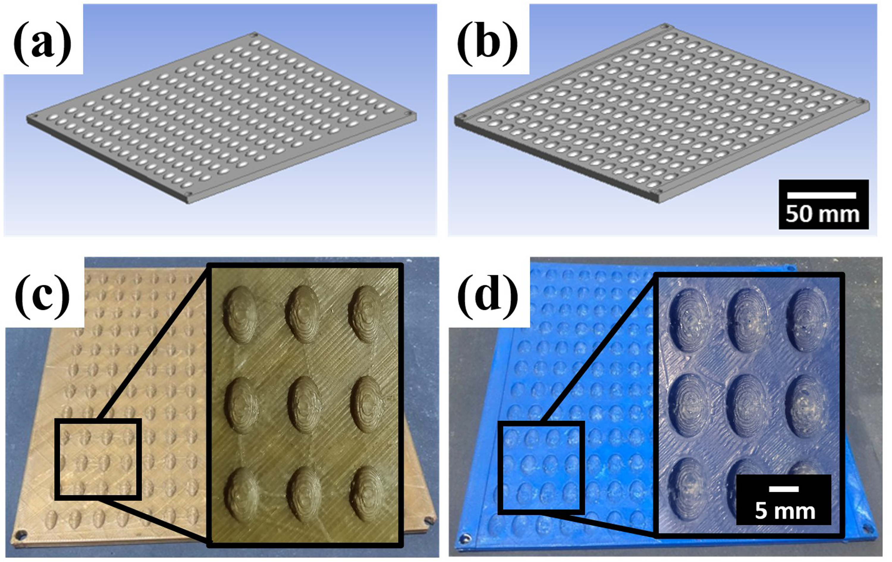
Pattern molds for ellipsoidal SHP manufacturing. (a, b) CAD models: Top and bottom parts. (c, d) 3D printed molds: top and bottom parts.
Aluminum foams manufacturing
Aluminum foams were manufactured using the previously obtained SHP and Al-319 as the base alloy, which was obtained from recycled car monoblocs, its nominal composition is shown in Table 1. This alloy offers advantages such as low cost, availability, and good fluidity due to its high Si content.
Nominal composition (in wt.%) of the Al-319 alloy.

The infiltration process was carried out using a device developed by our research group [Mexican Utility Model, MX/u/2023/000495, November 27th, 2024], which is shown in detail in Figure 3. This device comprises a dismountable cylindrical chamber made of AISI 314 stainless steel (Figure 3(d)), a foundry ladle (Figure 3(e)), and a gas injection cap (Figure 3(c)) equipped with a nozzle (Figure 3(a)) and a handle bar (Figure 3(b)). The first step for aluminum foams manufacturing was mounting the infiltration chamber and placing it inside the foundry ladle, both for better handling and for sealing the bottom of the chamber. After this, SHPs and the Al-319 alloy were loaded into the chamber, which was sealed at the top with the gas injection cap, and fully assembled (Figure 3(g)) using the security hose clamps (Figure 3(f)). Next, the fully assembled device was inserted in a PREFINSA resistance furnace (Figure 3(h) and (i)) at 700°C for 45 min to melt the aluminum alloy and complete the infiltration. Ar was injected gradually, with an initial flux of 10 ft3/h increasing by 15 ft3/h at intervals of 30 s until reaching the final flux of 45 ft3/h. Finally, the device was extracted from the furnace and allowed to cool down to room temperature, once at room temperature the chamber was dismounted to extract the aluminum foam. The SHP retained by the aluminum matrix were eliminated by dissolution in water for approximately 5 h for irregular grain particles and 1 h for ellipsoidal and spherical particles. A total of four samples with 53 mm diameter and 53 mm height were obtained for each SHP morphology.
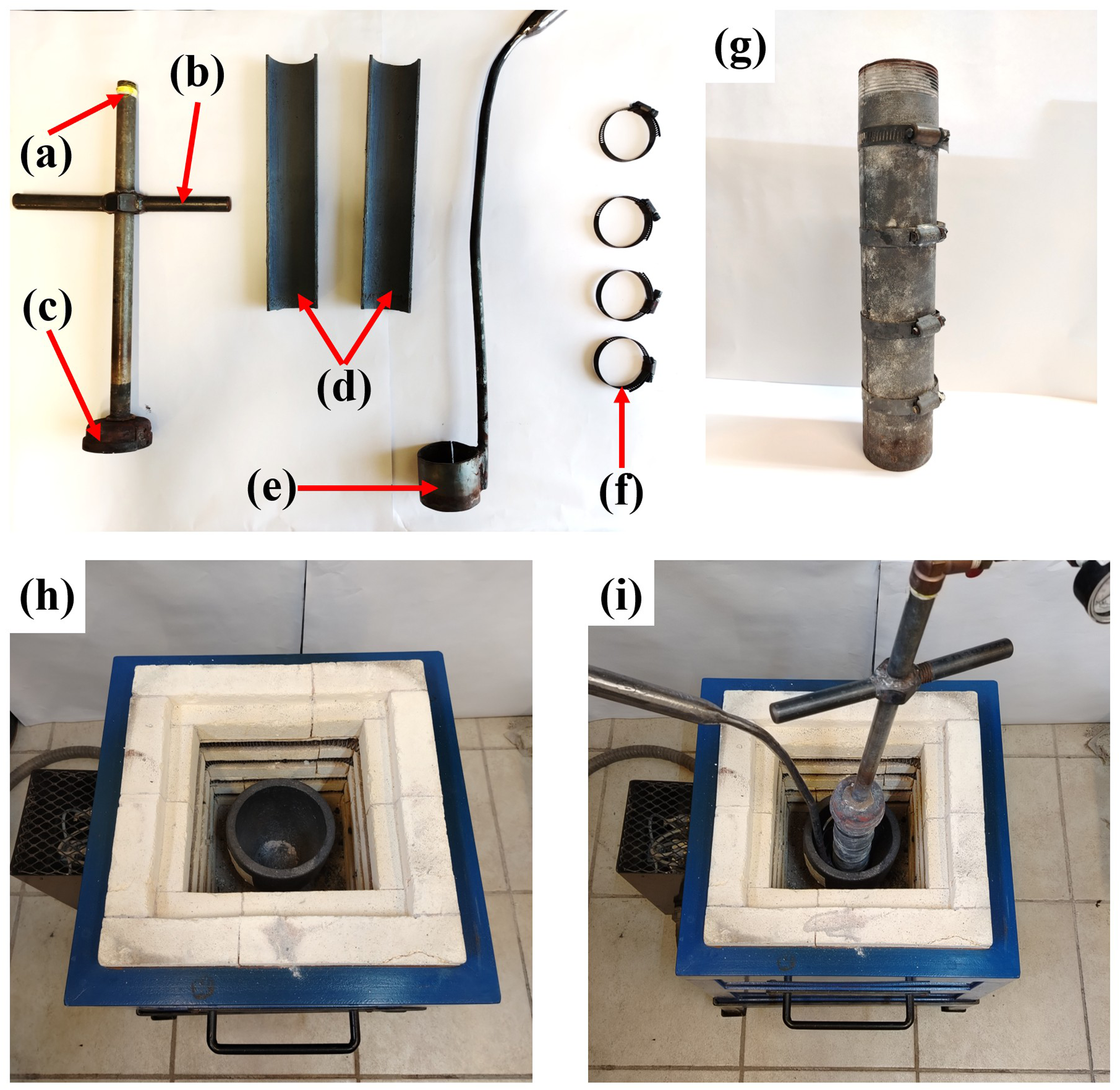
Infiltration device. (a–f) Parts, (g) Assembled infiltration chamber, (h) Resistance furnace, (i) Device positioned inside the furnace.
Structural characterization
Structural characterization included the measurement of density, porosity, and wall thickness. Density was determined from foams mass and volume, and used to calculate total porosity through Equation 1, where ρAl is the density of bulk aluminum and ρf is the density of the foam.
Finally, wall thickness was measured by image analysis technique using the free access software ImageJ 21 in its 1.53 version. A total of 8 images for each SHP morphology were obtained with a conventional camera and subsequently loaded into the software. The average wall thickness was obtained after defining the corresponding scale in the software. Measurements were performed drawing four diametral lines per image and measuring the width of every wall intersected by these lines with the aid of the software tool “Measure”.
Microstructural characterization
Microstructural characterization comprised a combination of Optical (OM) and Scanning Electron Microscopy (SEM). This analysis was focused on the characterization of the Al-319 alloy, both in as-cast condition and after the aluminum foams were manufactured. Three samples peer each condition were prepared using conventional metallographic techniques, without etching. In the case of OM, the equipment used was a metallographic microscope Labomed MET-400, with a LANOPTIK MCX501 camera incorporated for image acquisition. SEM images were obtained using a JEOL JSM-IT300 microscope equipped with a BRUKER double XFlash6130 EDS (Energy Dispersive Spectroscopy) detector. Images from both characterization techniques were analyzed using different software, for OM images iWorks version 2.0 was used to create scale reference measure. While in the case of SEM images the microscope automatically provides this reference. For phase identification and quantification, ImageJ 21 was used again, images were loaded to the software and converted to 8-bit format, subsequently the parameter known as “Treshold” was manipulated to indicate to the software which parts of the image correspond to a certain metallographic component.
Mechanical characterization
An Isostatic Compressive Test was conducted for characterization of mechanical properties using an INSTRON 1125-5500R Universal Mechanical Testing Machine. From the corresponding stress-strain curves Elastic modulus (E), Plateau stress, Densification and Absorbed Energy were measured following the procedures stablished by the ISO 13314 standard.
Computed tomography
Computed tomography tests were conducted with the purpose of obtaining relevant geometrical information about individual pore geometries from the different aluminum foams and finding their correlation with their mechanical properties. These tests were conducted using a Xradia Versa 510, while the analysis and measurements were performed with the aid of Avizo® software in its version 2023-2. One foam sample of each of the three different pore geometries was scanned, the samples were mounted on a plastic support and placed inside the equipment. After this, the equipment detector is aligned to ensure that the entire foam geometry is scanned, since the pores obtained in the foam samples are macro-sized, the equipment was configured to generate the reconstruction of each foam with 800 projections. For the analysis of the obtained CT images, the first step was to load the obtained projections to the software Avizo® and refine them to remove undesired elements such as air presence or residual projections containing parts of the plastic support. Following this, the “Interactive Threshold” tool was used to select which voxels correspond to the pores and which to the metallic matrix in the foam geometry, as shown in Figure 4. Thereafter the foams geometries were reconstructed in a 3D model. Up to this point this geometry is still interpreted by Avizo® as a single volume. Nevertheless, since the aim of using CT in this research work is to study individual pore characteristics, the software tool known as “Separate Objects” was used to separate them into individual cells. Finally, using the “Label” tool, the geometrical properties to be measured for each pore were defined, these included total porosity, 3D length, 3D thickness, 3D volume, Neighbor Cell Count, Orientation (φ) and Sphericity. It is worth mentioning that although the Xradia Versa 510 equipment has a resolution of 0.7 μm, data obtained from microscopical pores and defects were filtered since their effect is negligible for the analysis of macroscopic mechanical properties.
Use of “interactive threshold” for voxel selection: (a) Metal matrix. (b) Pores.
Results and discussion
Base alloy microstructural characterization
The Al-319 alloy in as-cast condition displayed a microstructure primarily constituted by a dendritic solid solution matrix (α-Al) with precipitation of secondary phases (Figure 5), which are analyzed in detail below.
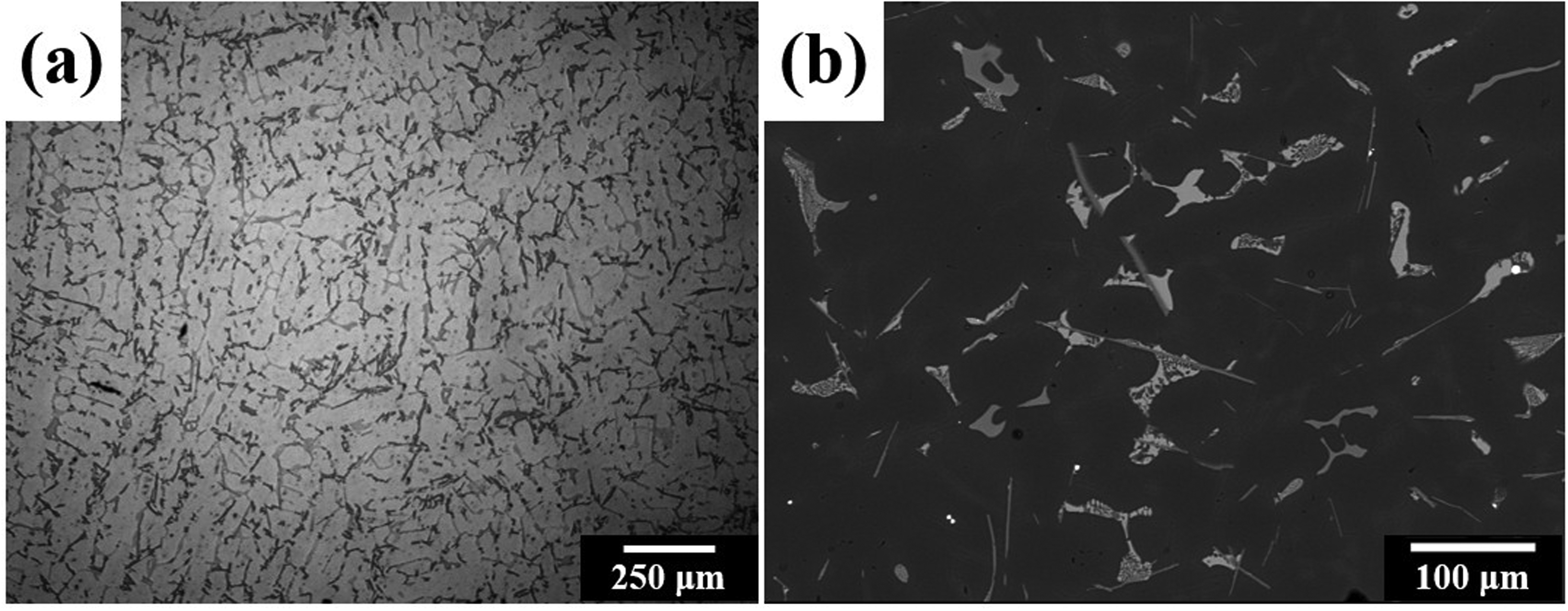
Microstructure of as-cast 319-aluminum alloy. (a) Optical micrograph. (b) SEM image obtained by backscattered electrons technique.
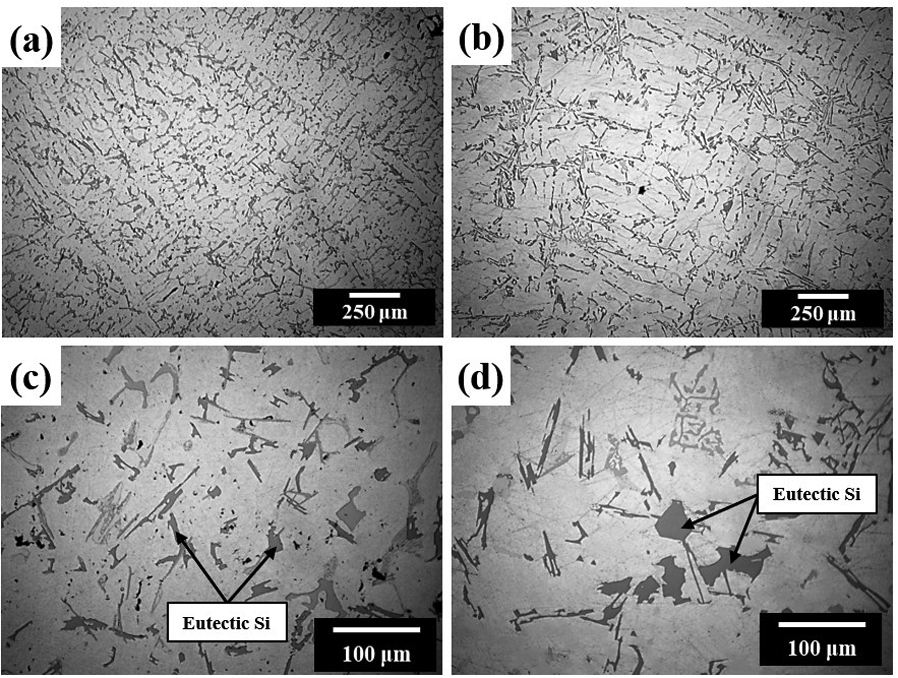
The obtained percentage for each secondary phase is reported in Table 2. Eutectic silicon was the phase identified in the highest percentage, mostly exhibiting a plate-like morphology but also displaying occasional elongated morphologies as shown in Figure 6(a). Although eutectic silicon was clearly identifiable by OM, Al2Cu was harder to detect because its brightness is similar to the α-Al matrix, making SEM necessary for proper identification. As seen in the SEM image in Figure 6(b), Al2Cu was observed with two different morphologies: plate-like and eutectic. The different morphologies presented by both phases, can be explained because of the variation in the phase nucleation and development due to the effect of cooling rate. While thicker plate-like phases have more time to develop and grow as a result of early nucleation, elongated silicon and eutectic Al2Cu are products of the latter solidification stages and thus have less time to grow. Fe-rich phases in minor quantities were also observed, predominantly block-like α-Al15(Fe, Mn)3Si2, and needle-like β-Al5FeSi in lower quantities. This occurred since the manganese content in the alloy helps to transform and stabilize α-Al15(Fe,Mn)3Si2 type phases, however low cooling rate provided by air at room temperature allows the formation of some residual β-Al5FeSi type phases. The presence of the corresponding elements for each secondary phase was confirmed with the aid of SEM Chemical Mapping, shown in Figure 6(c)–(f) (distribution maps for each element).

(a) OM and (b) SEM micrographs of the as-cast 319 Al alloy, highligting eutectic Si (1,2), Cu-rich secondary phases (3,4) and Fe-rich phases (5 and 6). (c–f) EDS Chemical mapping showing elemental distributions: (c) Aluminum. (d) Silicon (e) Iron (g) Copper.
Secondary phase percentage obtained for the As cast 319-aluminum alloy.
Aluminum foams
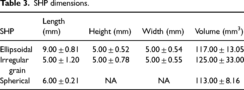
A comparison between the foams manufactured with the three different morphologies of the SHPs can be observed in Figure 7. Additionally, their dimensions are listed in Table 3.
Comparison between different SHP morphologies. (a) Spherical, (b) Irregular grain, (c) Ellipsoidal.
SHP dimensions.
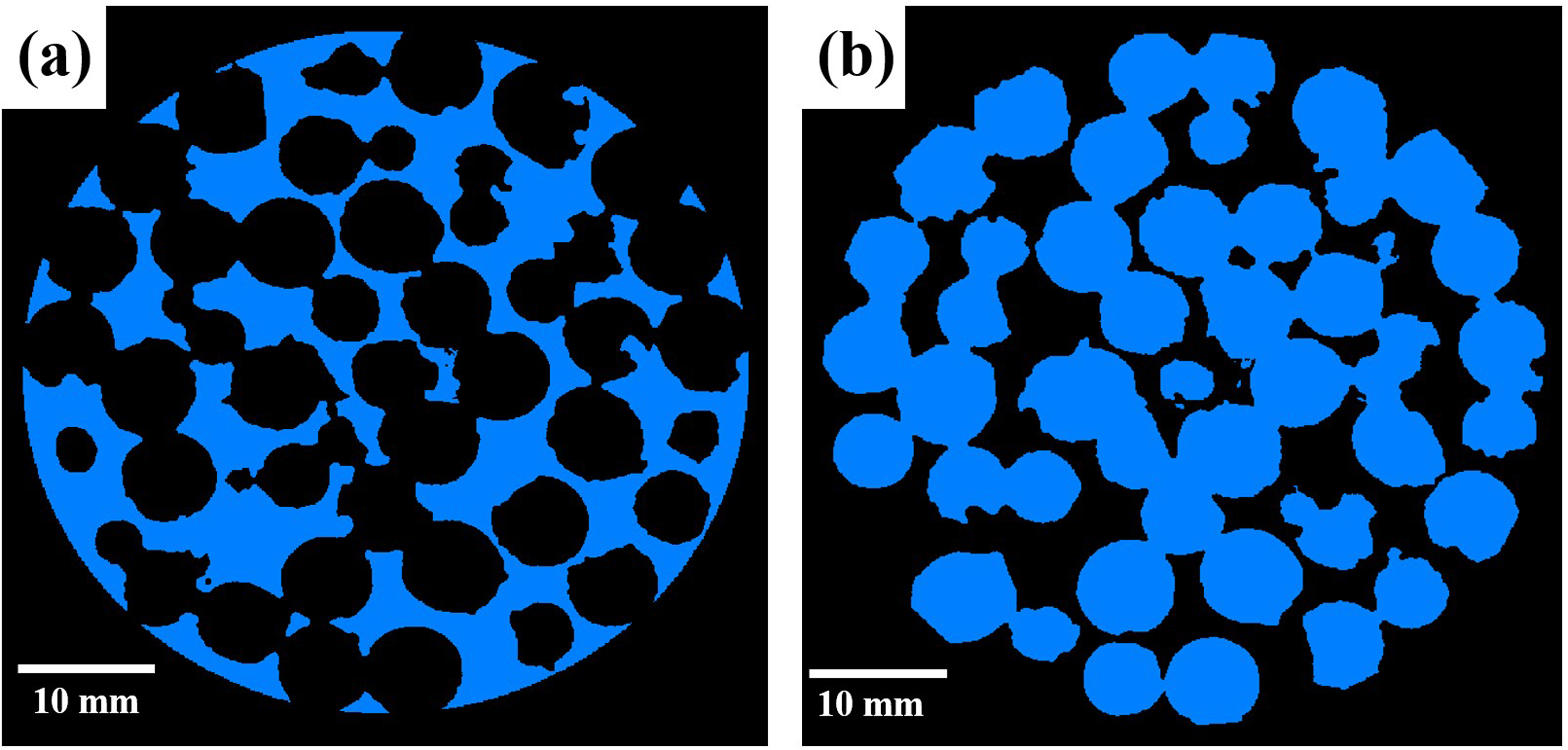
Aluminum foams exhibited homogenously distributed and interconnected pores, which retained the morphology of the SHPs used in their manufacturing. Figure 8(a)–(f) presents isometric and cross section views for the three different SHP morphologies.

Aluminum foams cross sections and isometric views. (a, b) Spherical pores. (c, d) Irregular pores. (e, f) Ellipsoidal pores.
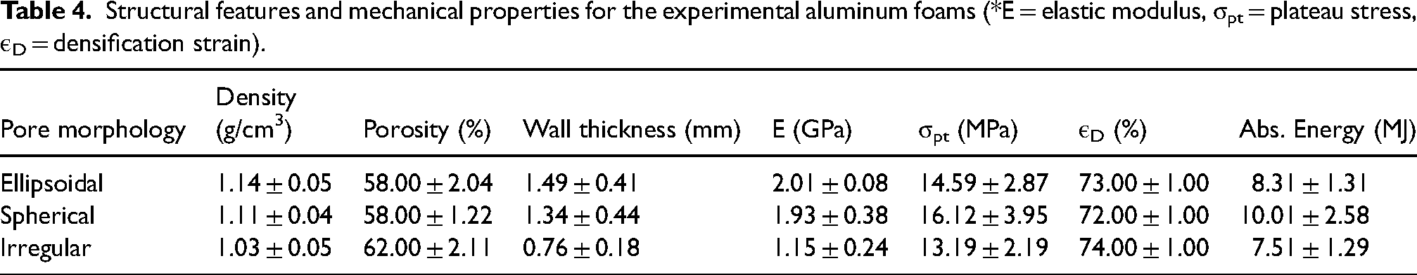
The structural characterization results presented in Table 4 show that the foams with spherical and ellipsoidal pores exhibited similar average porosity, while the maximum porosity was observed in foams with irregular pore morphologies. This behavior is directly related to the SHP morphology, since irregular grain particles can reach a higher packing density owing to their irregular polygonal morphology characterized by its angularity, thin sections and multiple semi-flat surfaces. These features tend to favor the reduction of empty spaces mainly as a consequence of coincident semi-flat faces or thinner particle sections inserted in empty spaces between other particles, phenomena that are not present for the cases of spherical and ellipsoidal particles. Foams obtained with irregular grain SHPs also displayed the lowest wall thickness, which can also be explained due to the higher packing density achieved by them, since the reduced empty space generates thinner infiltration channels and by consequence thinner pore walls. Table 4 shows that although foams with spherical and ellipsoidal pores showed closer values in porosity, ellipsoidal ones generated higher wall thicknesses. This could be explained as a result of their random orientation, since ellipsoidal SHP features three axes with one of them being longer, the particle positions tend to vary according to their longer axis causing the formation of thicker walls in some regions, which is reflected in the average value.
Structural features and mechanical properties for the experimental aluminum foams (*E = elastic modulus, σpt = plateau stress, εD = densification strain).
Microstructural characterization of the aluminum foams matrix revealed slight differences in comparison with the as-cast condition. As observed in Figure 9(a) (as-cast) and (b) (foams), a noticeable increase in dendrite size was observed. Figure 9(c) and (d) also showed that eutectic silicon presented a coarsening tendency in the foams microstructure. These changes are explained due to a lower cooling rate for the foams in comparison with the as-cast alloy. Although aluminum foams were also cooled in air at room temperature, the cooling process took place while SHP were still retained by the aluminum matrix. Considering the lower heat conductivity of NaCl particles, the cooling rate for aluminum foams decreased, giving α-aluminum dendrites and eutectic silicon more time to develop and grow.
OM microstructural comparison between as-cast (a, c) and aluminum foams (b, d) matrices.
Mechanical characterization
Mechanical testing was conducted successfully, as shown in the example illustrated in Figure 10(a)–(f), where a foam sample is presented at different deformation percentages during the isostatic compressive test. Additionally, examples of the obtained stress-strain curves for the aluminum foams with different pore morphologies are shown in Figure 11(a). As it can be observed, the stress-strain curves displayed the three characteristic zones of metal foams (elastic, plateau, densification). Nevertheless, a fluctuating behavior was observed in the plateau zone, generating different stress peaks and short sub-plateaus as strain is increased regardless of the pore morphology type. This behavior is attributed to the fact that plastic deformation took place gradually and in separated groups of cells.

Aluminum foam under uniaxial compressive test at diffent deformation pecentages: (a) 0%, (b)10%, (c)25%, (d) 40%, (e) 50%, (f) 80%.
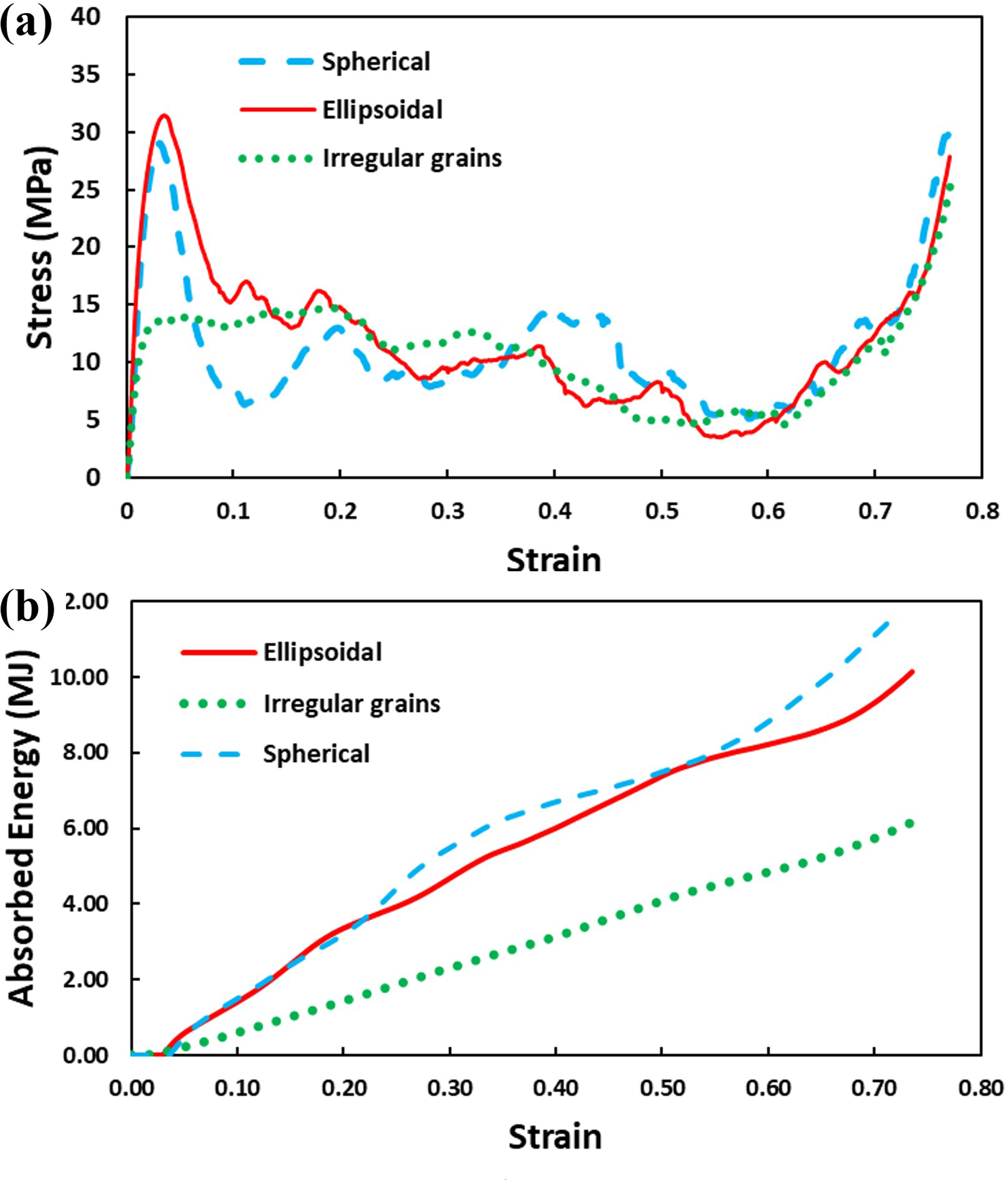
Aluminum foams mechanical behavior analysis. (a) Stress-strain curves. (b) Absorbed Energy curves.
To better illustrate the plastic deformation process, Figure 12 presents a separated example of an isolated stress-strain curve for an aluminum foam sample with ellipsoidal pores in conjunction with images obtained from the compressive test specimen at different strain percentages. This helps to clarify the different zones and the fluctuation along the plateau, which are described in more detail below:
Zone 1 (Z-1): The typical elastic zone is observed, once yield point is reached, the stress reduces instantly to initialize the plastic deformation in a first cell group, originating the first plateau. Zone 2 (Z-2): Previously collapsed cells conclude their plastic deformation and densify, while a second group of cells starts plastic deformation, generating a sudden increase in the stress and reaching a new maximum point in which yield of the second group of cells took place, then reducing the stress and forming a new short plateau. Zone 3 (Z-3): The cycle described in Zones 1 and 2 is repeated two more times with new groups of cells. Zone 4 (Z-4): At the end of the stress-strain curve, a final increase in the stress could be observed, indicating that all the cells of the foam are collapsed and the aluminum foam has been totally densified.
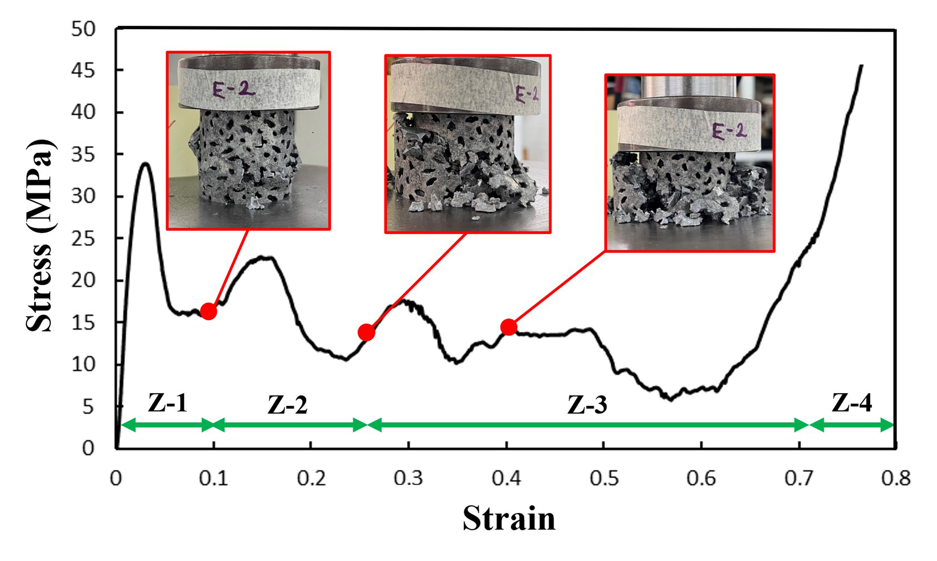
Analysis of fluctuation in aluminum foams plateau zone.
A summary of the mechanical properties is shown in Table 4. As expected, Elastic Modulus showed a decreasing tendency as porosity increased. This property was also affected by wall thickness. This can be deducted from the fact that the foams with ellipsoidal pores (which have thicker walls) showed a higher modulus than those with spherical pores, despite having close porosity values. In a comparable way to Elastic Modulus, Plateau Stress was significantly influenced by porosity and wall thickness. Irregular particles showed the lowest value since they featured the higher porosity and the thinner cell walls, which grant these foams with lower resistance to compressive loads. Nevertheless, Plateau Stress showed a particular behavior in foams with ellipsoidal and spherical pores. Despite exhibiting similar porosity, foams with spherical pores showed a higher Plateau Stress, even though those with ellipsoidal pores presented higher wall thickness. This behavior was attributed to the ellipsoidal SHP morphology, as previously mentioned these particles feature a longer axis, making them prone to collapse due to the irregular distribution of the applied compressive load, which tends to concentrate in the shorter axes, especially for perpendicular loads. Besides, once in a particle volume, ellipsoidal particles tend to random orientation, generating pore zones with lower resistance to compressive loads. On the contrary although spherical particles can present morphological defects, the difference in the dimension along their axes is significantly lower in comparison with ellipsoidal ones, this effect is also confirmed by the CT analysis and will be discussed in their correspondent section. Hence, spherical particles can feature a better load distribution for both, a single particle and a volume of particles. These results are coincident with previous research works like the ones conducted by Yu et al. 22 and Xia et al. 23 Plateau stress behavior was reflected in aluminum foams energy absorption capacity, Table 4 shows the direct relationship between these two properties. Considering that energy absorption capacity of a foam is given by the area under the stress-strain curve, a higher average Plateau Stress provides a higher energy absorption capacity. This difference is better illustrated in Figure 11(b), which shows the energy absorption capacity as a function of strain.
Computed tomography
3D pore reconstructions were successfully obtained through CT scans. Additionally, individual pore geometries were obtained using Avizo® as shown in the longitudinal view presented in Figure 13, while a cross-sectional view can be observed in Figure 14. These 3D models facilitated the observation of packing density for the different pore geometries, it can be noted that the model with irregular pores exhibits fewer empty spaces between pores compared to spherical and ellipsoidal ones, confirming the higher pore density achieved by using irregular space holders.
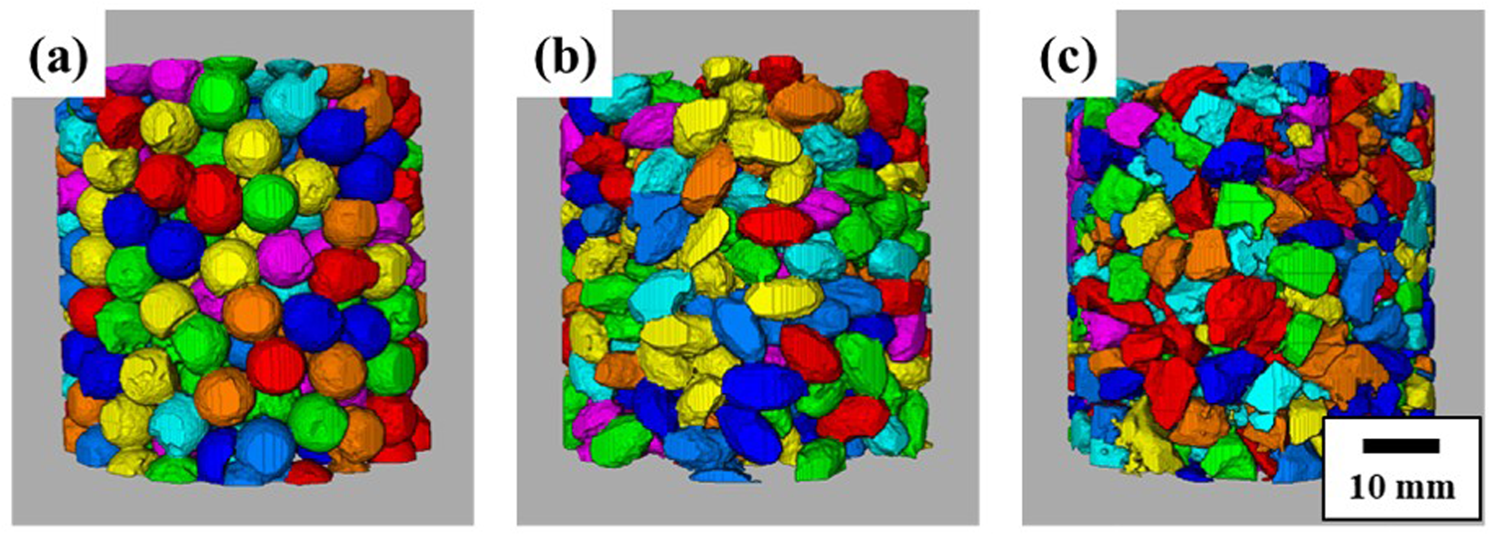
3D pore models longitudal view. (a) Spherical, (b) Ellipsoidal, (c) Irregular.
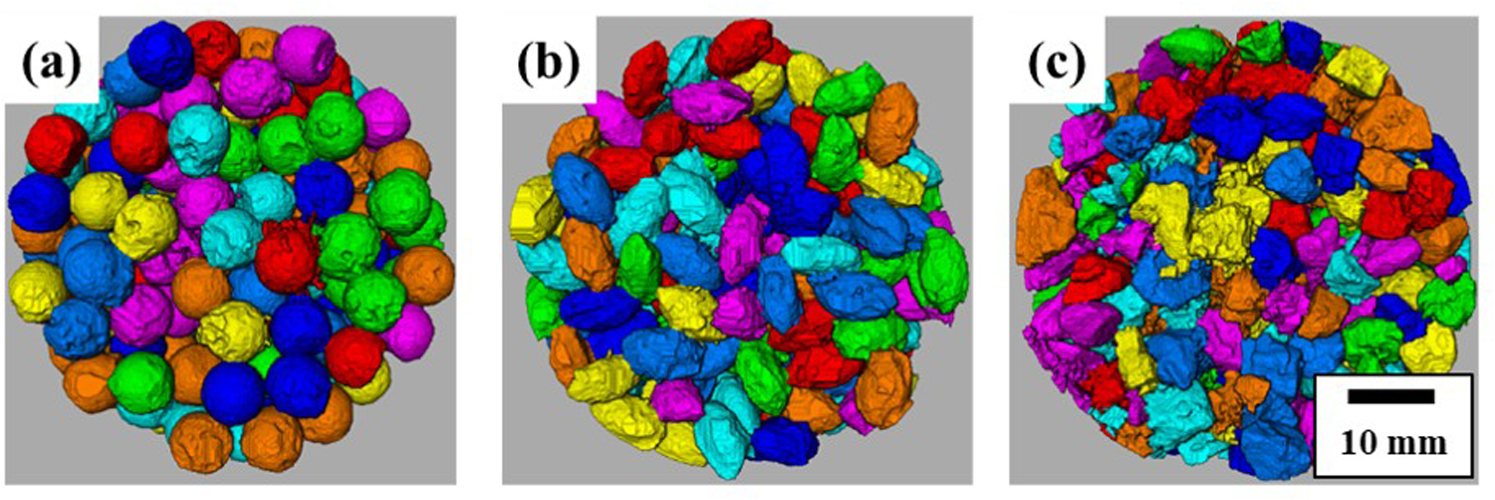
3D pore models cross sectional view. (a) Spherical, (b) Ellipsoidal, (c) Irregular.
Furthermore, 3D metallic matrix models for each foam are displayed in Figure 15. It can be noted that these models accurately resemble pore morphology and distribution from experimental aluminum foams previously shown in Figure 8.
3D metal matrix models. (a) Spherical, (b) Ellipsoidal, (c) Irregular.
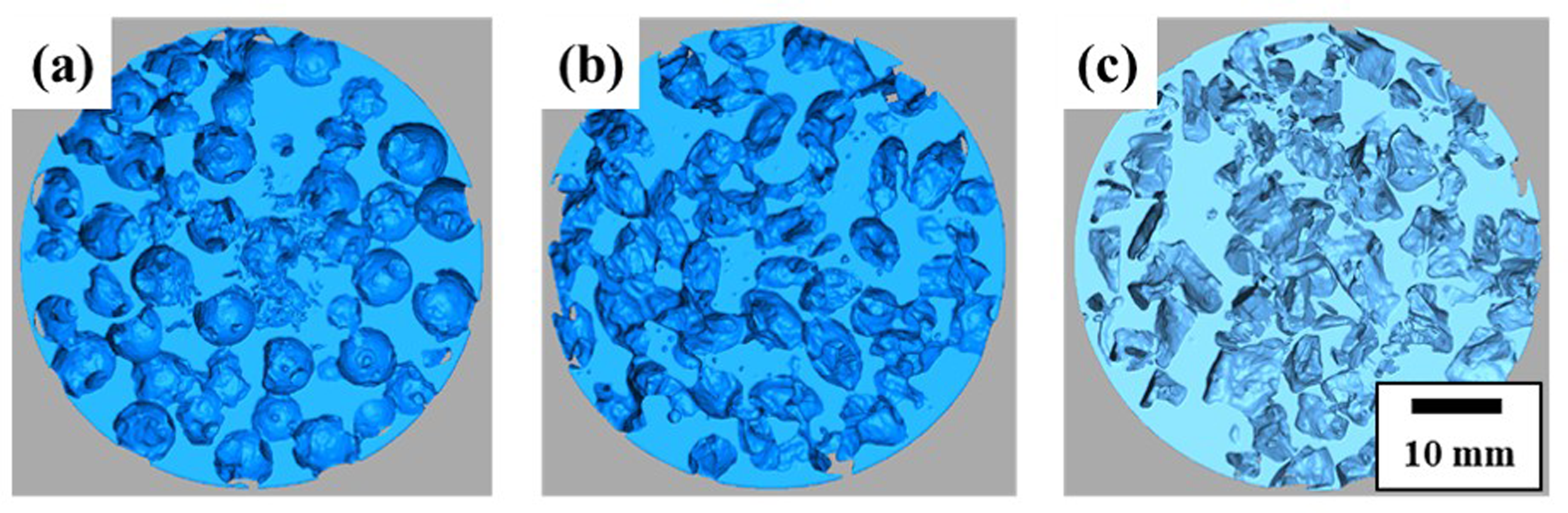
Characterization results of individual pores are presented in Table 5, and as observed total porosity showed close values in comparison with the porosity measured in experimental foams using the theoretical definition for density, showing a slight variation in the order of 1 to 3%. Additionally, all the pore morphologies maintained the same tendency for total porosity, with irregular grain SHP showing the highest porosity percentage, while the spherical and ellipsoidal ones exhibited similar values. Some of the properties measured in 3D reconstructions obtained from CT such as 3D length, 3D thicknesses, 3D volume showed an overestimation in comparison with the equivalent properties measured in experimental SHP for all the different morphologies. This can be explained mainly by SHP irregularities due to the manual manufacturing process and to the error margin from the functions “Separate Objects” and “Interactive Threshold”. Besides this, the coalescence phenomenon also contributes to this overestimation, as pores sharing large portions of volume could be misidentified as a single entity by Avizo®. This is shown in the 3D volume histograms in Figure 16, as it can be observed 3D volume presented a wide variation for the aluminum foams with different pore morphologies.
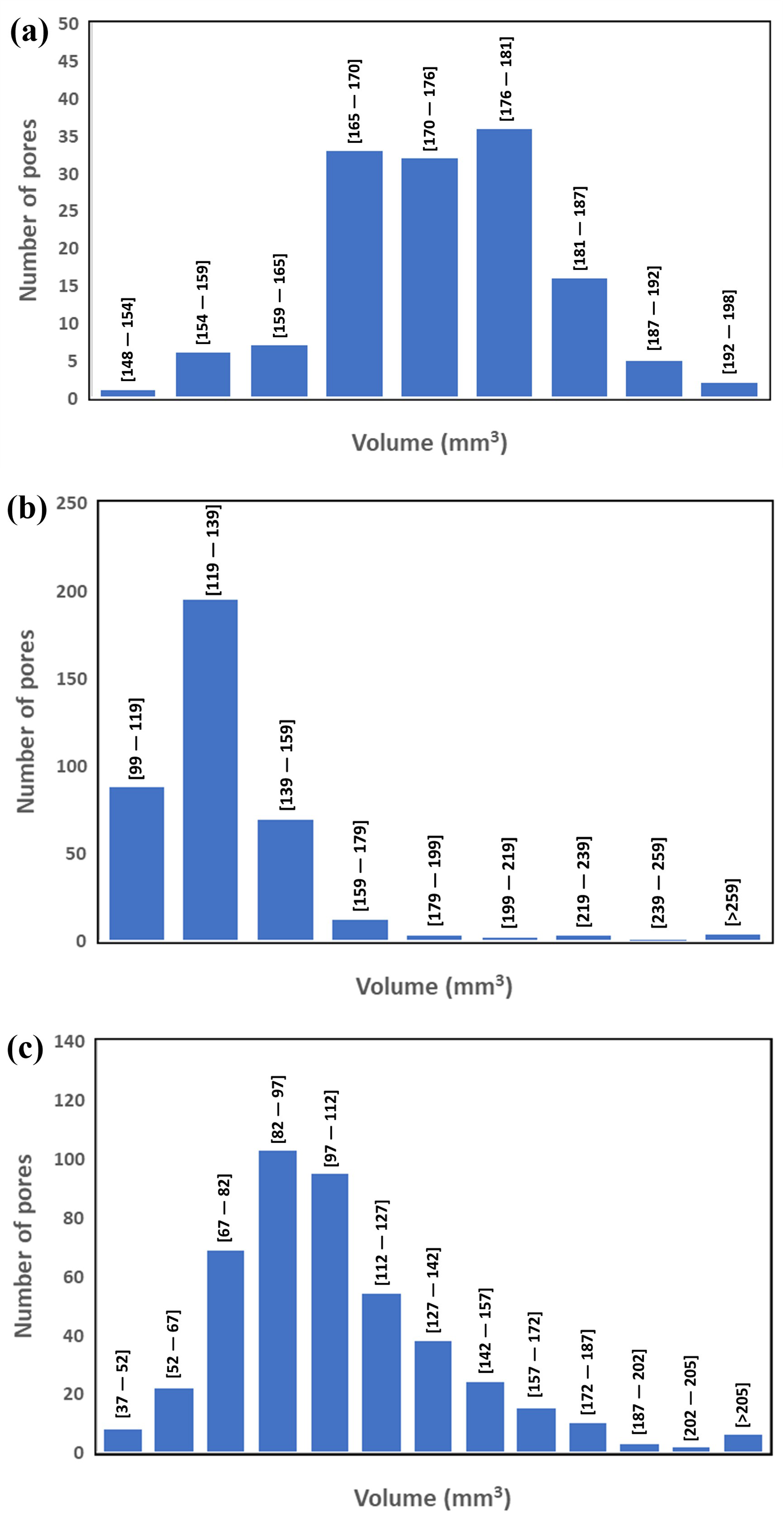
3D volume distribution for aluminum foams with different pore morphologies: (a) Spherical. (b) Ellipsoidal. (c) Irregular.
Computed tomography characterization results.
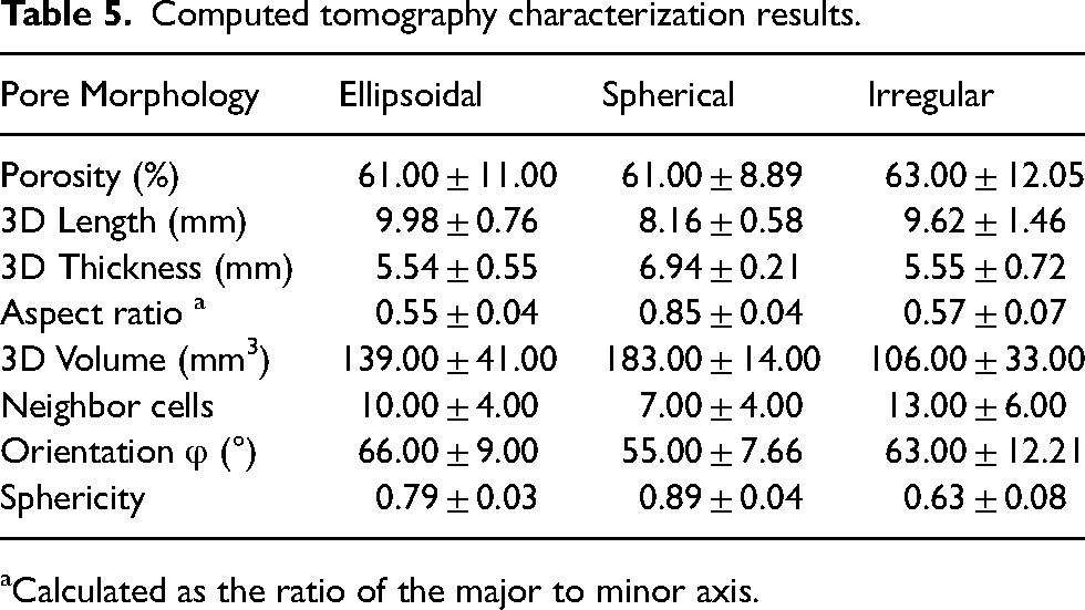
Calculated as the ratio of the major to minor axis.
Other relevant properties obtained from CT characterization were the Aspect ratio and Sphericity, since they were helpful to confirm the effect of SHP morphology in mechanical properties like Plateau Stress and Energy Absorption Capacity. As observed in Table 5, spherical pores exhibited Aspect ratio and Sphericity values closest to 1, indicating better resistance to plastic deformation under compressive loads, as previously explained. Additionally, in Table 5 it was also noticeable that foams with spherical pores presented the lower Neighbor Cells count, which is also a factor that affects foams Plateau Stress and Energy Absorption Capacity, since lower contact points with neighbor cells generate cell walls with better continuity. From Table 5, it was also possible to observe the average pore orientation with respect to the xy plane, that is the circular faces of the specimens. Although all the geometries presented a certain degree of inclination, the effect on the mechanical response to compressive stress was more pronounced for ellipsoidal and irregular pores. This can be explained by the fact that these geometries presented Aspect ratio and Sphericity values with greater deviations from 1 in comparison with the spherical ones. As previously mentioned, these characteristics lead to an irregular load distribution and by consequence an aluminum foam with less resistance and lower energy absorption capacity in comparison with foams with spherical pores.
The pore morphology influence was validated by comparison with mathematical models for elastic modulus prediction. The first was the Gibson and Ashby model
24
which calculates this property as function of relative density as shown in the Equation 1, where E is the aluminum foam elastic modulus, E0 is the elastic modulus of bulk aluminum alloy, D is the foams relative density and n is a constant value.
The second one proposed by Nielsen
25
considers a pore shape factor to predict the elastic modulus of porous materials as shown in Equation 3, where E is the elastic modulus of the aluminum foam, E0 is the elastic modulus of bulk aluminum, P is porosity and Ff is the shape factor.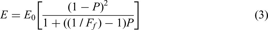
For this research, the shape factor in the Nielsen equation was replaced by sphericity obtained from CT analysis. This morphological feature was selected due to the fact that it displayed a similar behavior to the experimental elastic modulus, with ellipsoidal and spherical pores having higher and closer values between both properties in comparison with irregular pores. Results obtained for elastic modulus calculated with the reference models are compared with experimental results in Table 6.
Experimental elastic modulus comparison with reference models.
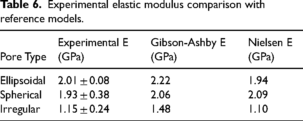
As it can be observed from Table 6, although both reference models achieved good approximation for the elastic modulus of aluminum foams, the modified Nielsen model using sphericity as shape factor presented a better approximation for the case of irregular pores in comparison with the Gibson-Ashby model. These results allow to confirm that pore shape originated by SHP morphology had an important impact on the mechanical properties of aluminum foams.
Conclusions
After the study of the three different pore geometries obtained in the experimental aluminum foams, the following conclusions can be written.
Morphology of Space Holder Particles proved to be a relevant factor, with significant impact on structural properties, like wall thickness, and mechanical properties, such as elastic modulus and energy absorption capacity. This confirms SHP morphology as a critical parameter in infiltration method. Strong correlation between aspect ratio and mechanical performance of aluminum foams was demonstrated as pores with aspect ratios deviating further from 1 showed lower energy absorption capacity, due to their reduced ability to uniformly distribute the applied compressive load. Aspect ratio also exhibited a noticeable influence over particles orientation. As a result of values deviating further from 1, ellipsoidal and irregular pores exhibited uneven lengths on their axes, leading to non favorable orientations with respect to the compressive load, ultimately reducing aluminum foams energy absorption capacity. Foams with spherical pores presented a better resistance and energy absorption capacity due to their aspect ratios significantly closer to 1, besides orientation of particles did not represent great influence on this pore morphology due to the better uniformity in their corresponding axes. Angularity of irregular particles proved its relevance on mechanical properties, as demonstrated by a reduction on elastic modulus close to 50% for this pore morphology, which is linked to a substantial decrease in wall thickness caused by better packing density allowed by irregular SHPs. Computed Tomography models displayed high accuracy in comparison with experimental foams, with a minimal porosity deviation (≈3%), confirming this method as a valuable tool for aluminum foams analysis.
Footnotes
Acknowledgments
Authors acknowledge Universidad Nacional Autónoma de México (UNAM) for the academic support for this research trough the Materials Research Institute (IIM) and Geoscience Institute (IGC). Authors also would like to acknowledge The Faculty of Mechanical Engineering and The Institute for the Earth Science Research from Universidad Michoacana de San Nicolas de Hidalgo (UMSNH). Ismeli Alfonso acknowledges the financial support from UNAM PAPIIT IN102322.
Author contribution(s)
Declaration of conflicting interests
The authors declared no potential conflicts of interest with respect to the research, authorship, and/or publication of this article.
Funding
The authors disclosed receipt of the following financial support for the research, authorship, and/or publication of this article: Ismeli Alfonso acknowledges the financial support from UNAM PAPIIT IN102322. Christian Reyes would like to acknowledge SECIHTI for the financial support through the grant for Doctoral Studies (893763). H. Mecinas and O. Hernandez are acknowledged for their technical support in mechanical and SEM analyses, respectively.