
Abstract
The fretting corrosion characteristics of 316L and the plasma carburized layer (PCL) in various corrosive-lubricating solutions were investigated. In neutral solution and distilled water, both 316L and PCL exhibited fatigue peeling and adhesive wear, with material loss primarily driven by mechanical action and minimal corrosion-wear interaction. Exposure to seawater and acid rain resulted in adhesive wear, corrosive wear, and fatigue peeling for 316L. PCL showed adhesive wear and corrosive wear. The material loss resulted from both mechanical action and corrosive-wear interaction. Reactive ions exacerbated the corrosive-wear interaction, increased wear amount, and reduced friction coefficient. The frictional energy dissipation coefficient, wear rate, and depth of PCL were relatively low. PCL improved the corrosion-wear resistance and stability of 316L, offering effective protection.
Keywords
Introduction
Nominally stationary fasteners or components experiencing minimal displacement amplitudes in the micrometer range, such as bearings, bolts, and human implants, are susceptible to fretting. This leads to wear and fatigue at contact surfaces, causing misalignment, failure, and power loss.1–5 Fretting corrosion refers to the wear experienced by components in electrolytic or corrosive environments, where both corrosion and wear contribute to abnormal wear or premature fatigue of fasteners. The combined influences of chemical, mechanical, and electrochemical actions lead to fretting corrosion,6,7 which is commonly observed in fields such as energy, marine, land transportation, aerospace, and biomedicine.8,9 Nuclear fuel cladding materials, heat transfer tubes, support plates in high-temperature and high-pressure steam environments, aircraft (whether parked or flying over oceans), artificial implants in bodily fluids, and high-speed railway components exposed to rainwater are all susceptible to fretting corrosion.10–14
Austenitic stainless steel is extensively employed in marine, aerospace, biomedical, petrochemical, and nuclear industries owing to its remarkable properties, including high ductility, biocompatibility, formability, and weldability.15–20 However, the poor wear resistance and low hardness of austenitic stainless steel make it vulnerable to corrosive wear in environments with high concentrations of halogen elements or acid anions. Consequently, its corrosion and wear behaviour has been investigated in artificial bodily fluids, high-temperature and high-pressure water, acidic and alkaline solutions, oil and gas environments, marine conditions, and acid rain.3,21–26 Corrosive-lubricating media modify the wear mechanism of stainless steel, leading to corrosive-wear interaction. The boundary lubrication enhancement effect contributes to an increase in corrosive wear.27–29
Surface modification techniques improve the wear and corrosion resistance of various materials, therefore increasing the lifetime of the components in corrosive environments.30,31 Various surface modification techniques are utilized to enhance the corrosion and wear resistance of austenitic stainless steel, including laser shock peening, plasma nitriding, magnetron sputtering, laser cladding, thermal spraying, and ion implantation.21,32–38 For instance, low-temperature plasma carburizing (LTPC) at temperatures below 500 °C can effectively remove adhered films on stainless steel surfaces. This process utilizes glow discharge to eliminate surface contaminants, allowing carbon atoms to infiltrate the material and fill voids at internal grain boundaries, dislocations, and other defects. As a result, an Sc phase is formed, enhancing corrosion wear resistance and surface hardness.39,40 Scholars suggested that low-temperature nitriding is more effective in dry, non-corrosive environments, whereas low-temperature carburizing is better suited for corrosive environments containing H2SO4.35,41,42 Reinders 43 developed a corrosion model to predict the S phase thickness and the associated changes in corrosion behaviour during the ion nitriding of austenitic stainless steel. Landek 44 reported that an excessively long nitriding duration reduced the wear resistance of 316L and significantly impacted its pitting corrosion resistance, though its overall corrosion stability remained unaffected. Other scholars45–48 explored the key failure factors and mechanisms of 316L under corrosion and wear in molten lead-bismuth eutectic (LBE), artificial saliva, and varying dissolved oxygen (DO) concentrations. They proposed a model to predict corrosion-induced wear and quantify the corrosive-wear interaction. Investigating the corrosion behaviour of 316L under periodic motion, Liu found that repeated sliding refined the grain structure in the contact area while mechanically removing the passivation film. This led to abrasive wear, exacerbating the wear of 316L and increasing the wear volume associated with intermittent corrosion. 24 In conclusion, the corrosive wear of 316L primarily involves the conventional sliding corrosive wear mode, with various surface strengthening parameters affecting its performance. However, research on the fretting corrosion characteristics of 316L in corrosive-lubricating media is limited. As a result, the synergistic interaction mechanisms of wear and corrosion in fretting corrosion remain unclear.
In this study, the LTPC technology was employed to fabricate a plasma carburized layer (PCL) on the surface of 316L. The fretting corrosion characteristics of both PCL and 316L were assessed in four representative water-based corrosive-lubricating solutions: simulated seawater (S), simulated acid rain (A), neutral solution (N), and distilled water (D). The evaluation was conducted under varying loads via an SRV-V fretting friction and wear tester. The chemical composition, wear scar morphology, friction coefficient (μ), and wear profile were analyzed, while the cutting plasticity ratio (fcp), wear rate (K), frictional energy dissipation coefficient (αe), and corrosion-wear interaction ratio (λ) were calculated. The fretting corrosion characteristics and mechanisms of 316L before and after LTPC were comprehensively examined from mechanical, chemical, and energy perspectives to elucidate corrosion-wear interactions. This study offers experimental insights for a deeper understanding of fretting corrosion behaviour in practical engineering applications.
Experiment
Experimental materials and preparation of carburizing layer
Commercial 316L stainless steel (Φ24 mm × 8 mm cylinder) was chosen as the lower sample. Each sample was manually polished, followed by mechanical polishing using 180 # to 3000 # SiC metallographic water abrasive paper to achieve mirror surfaces. The samples were then washed and dried with acetone and alcohol before use. The chemical composition of 316L (wt.%) was as follows: 16.45% Cr, 10.01% Ni, 2.10% Mo, 0.92% Mn, 0.36% Si, 0.03% C, and the balance Fe. The 316L had a surface hardness of 273 ± 33 HV0.2, a surface roughness (Ra) of 0.147, and a γ-Fe phase structure. 49
The PCL was prepared utilizing an LDMC-30F glow plasma carburizing and diffusion furnace. LTPC was conducted at 450 °C with a voltage equal to 800 V and a current equalling 8 A for 10 h. The flow rates of H2 and C2H2were maintained at 0.7 L/min and 0.063–0.077 L/min, respectively. Following LTPC, the resulting PC sample demonstrated a surface hardness equal to 897 ± 18 HV0.2 and an Sc phase structure incorporating elements such as Cr, Fe, Ni, and C. The surface roughness (Ra) was measured at 0.187, with a film thickness of 25 µm. Detailed characterization and analysis of the carburized layer are available in reference. 49
Fretting friction and wear experiment
An Optimol SRV-V fretting friction and wear tester was utilized to perform fretting wear experiments in a ball-plane contact configuration between the upper and lower specimens. A schematic illustration of the fretting wear tester is presented in Figure 1. The upper sample was a Φ10 mm GCr15 ball with the following elemental distribution (wt.%): 0.30% Si, 0.30% Mn, 0.08% Mo, 1.00% C, 1.60% Cr, and 96.72% Fe. The GCr15 ball had a surface hardness of 62–65 HRC and a machining accuracy of G10, as provided by the supplier. The evaluated friction pairs were GCr15/316L and GCr15/PCL.
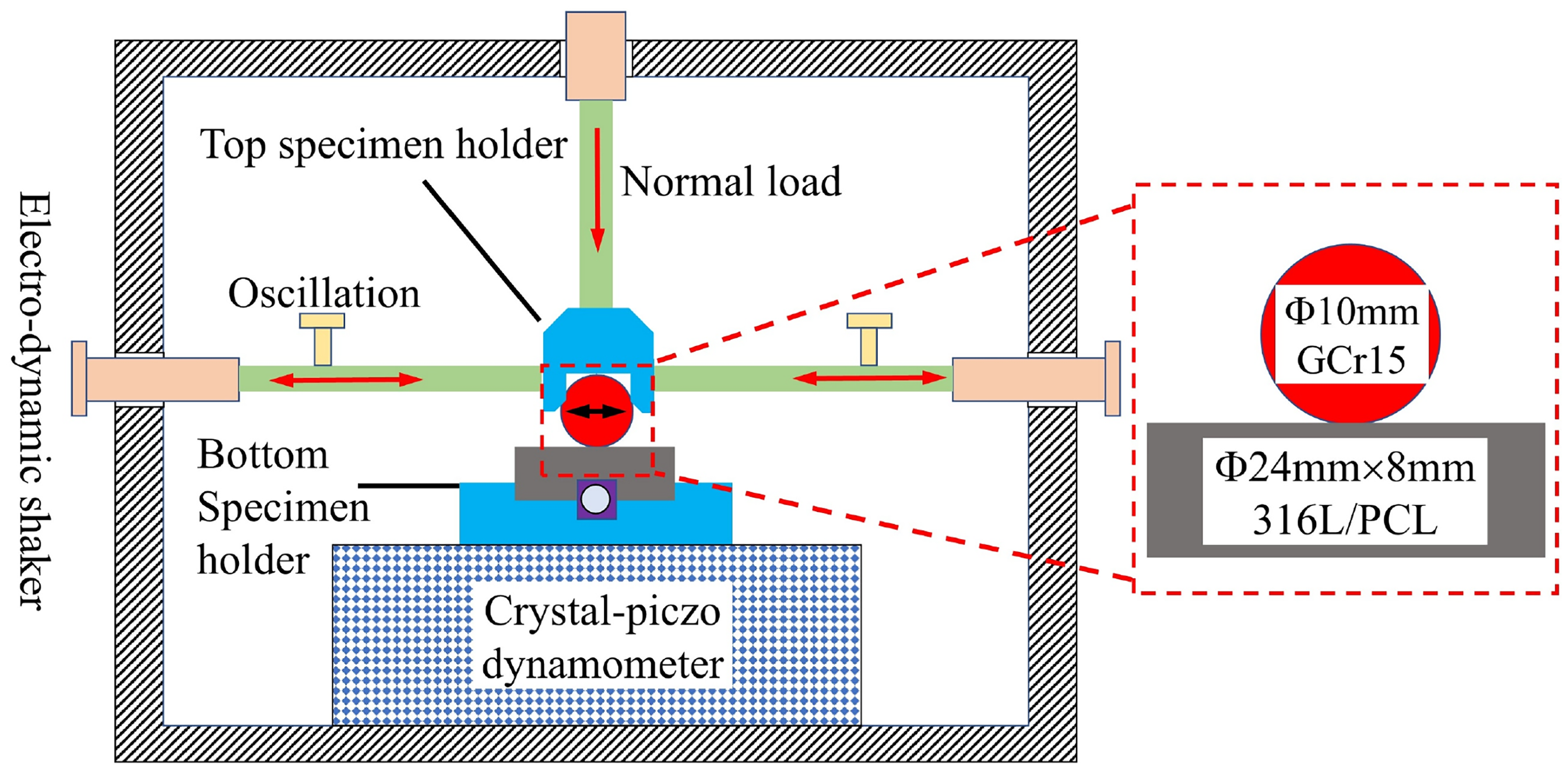
The schematic illustration of the principle of fretting wear tester.
Normal loads were applied at 30 N, 50 N, and 70 N, with testing conducted at a displacement amplitude equal to 70 μm, a frequency of 25 Hz, and a total of 3 × 10⁴ cycles for 20 min. Simulated seawater (S), simulated acid rain (A), neutral solution (N), and distilled water (D) were used as corrosive-lubricating media, with their specific compositions provided in Table 1. The selected solutions were obtained from the laboratory, and the specific ratios are confidential, as per the supplier's requirements. During each fretting wear test, the corrosive-lubricating solution was injected into the contact area every 2 min using a disposable syringe, ensuring complete immersion of both the upper and lower specimens. The surface of each specimen was cleaned with alcohol prior to each test. Each experimental group was tested three times, and the most stable set of results was selected for analysis.
The specific compositions and pH values of three corrosive media.
Performance testing and characterization
An FEI QUANTA FEG 450 field emission scanning electron microscope (SEM), integrated with an energy-dispersive X-ray spectrometer (EDS), was utilized to study the wear morphology and elemental composition of the prepared samples. The wear scar morphology, wear profile, and wear volume were analyzed using an OLYMPUS OLS5000 3D laser scanning confocal microscope (LSCM). The friction coefficient was automatically recorded during the friction and wear testing.
Results
Friction coefficient analysis
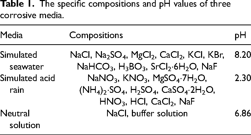
The friction coefficient plots of PCL and 316L in various corrosion solutions exhibited two distinct stages, as shown in Figure 2(a)–(d).45,50 (1) Running-in stage I. Contact between the upper and lower specimens disrupted the surface-attached oxide film and removed surface contaminants, exposing the “fresh metal” surfaces, which then came into contact. The contact mode was characterized by “micro-convex - micro-convex” two-body contact. During this stage, frictional resistance increased, grinding debris was generated, and the friction coefficient rose sharply, reaching its maximum value. Due to the relatively small actual contact area and high contact stress, the initial contact state was unstable, leading to significant fluctuations in the value of the friction coefficient. (2) Stable stage II. During the middle and later stages of the fretting corrosion process, the solution penetrated the interface, and the micro-convex body was smoothed. Consequently, the contact area increased, contact stress decreased, and fretting corrosion occurred.
The friction coefficients of PCL and 316L in (a) distilled water, (b) neutral solution, (c) simulated seawater, and (d) simulated acid rain. (e) The mean friction coefficient of 316L and PCL in various solutions.
The friction coefficients of PCL and 316L in the same solution followed the trend μ30N > μ50N > μ70N. The PCL exhibited more stable friction coefficient curves than 316L, with no significant fluctuations. Under higher loads, anions (
316L exhibited higher average friction coefficients than the PCL in all four solutions, as shown in Figure 1(e). The uniform and dense structure of the carburized layer resulted in grain refinement and an increased number of grain boundaries. The presence of more grain and sub-grain boundaries impeded dislocation movement, enhancing the strength and hardness of the carburized layer.
15
As a result, wear damage was less likely to occur. Under the same load, the friction coefficients of both materials followed the order μD > μN > μS > μA. The cooling effect of the solution substantially reduced the likelihood of reaching the frictional flash temperature at the contact surface, weakening the adhesion effect. The presence of the solutions at the contact interface induced a boundary lubrication effect, which slowed mechanical wear at the interface and contributed to a reduction in the friction coefficient.
52
Unlike distilled water, the other three solutions contained active anions such as
Wear scar morphology and composition analysis
The wear scars of PCL and 316L in distilled water are presented in Figure 3. The 316L sample exhibited pronounced furrow morphology with larger furrow dimensions compared to PCL. Under a load of 30 N, the wear scar on 316L displayed a few wear pits and micro-cracks, with a small amount of fine wear debris scattered within the pits (Figure 3(a1)). At 50 N, the wear scar revealed both wear pits and a large area of flaked material (Figure 3(b1)). Interlaced micro-cracks were found on the surface of the remaining material, which would eventually flake off to form wear debris. Due to the relative motion and rolling of the upper specimen, the fatigue spalling area exhibited a distinct fish-scale-like morphology, resulting from the competition between the adhesion effect of 316L and the lubricating effect of the solution. The spalling edges appeared bright white, indicating that 316L experienced plastic deformation at the delayed boundary due to fatigue spalling. The scattered wear pits aggregated and connected under a load equal to 70 N, forming grooves of remarkable depth (Figure 3(c1)).

Wear scar morphologies of 316L in distilled water at (a1) 30 N, (b1) 50 N, and (c1)70 N. Wear scar morphologies of PCL in distilled water at (a2) 30 N, (b2) 50 N, and (c2) 70 N.
Moreover, the increased size and depth of the wear pits exacerbated the adhesion effect. The presence of the solution in the contact area created a sealing effect, leading to an insufficient oxygen supply at the centre of the wear track. Consequently, oxygen concentrations differed between the inside and outside of the wear track. Oxygen corrosion primarily occurred at the edges, where wear debris flowed more easily and was more prone to furrowing. 53 The wear mechanism of 316L was characterized by adhesive wear and fatigue peeling, accompanied by a severe furrow effect. The wear scars of PCL in distilled water exhibited continuous furrows of varying depths at lower loads equal to 30 and 50 N, consistent with the motion direction of the upper specimen (Figure 3(a2, b2)). Under a load of 70 N, a third layer formed due to the accumulation of wear debris, and material spalling and micro-cracks were observed (Figure 3(c2)). The wear mechanism of PCL transitioned from adhesive wear to a combination of fatigue peeling and adhesive wear, accompanied by a furrow effect.
The wear scars of 316L and PCL in neutral solution are depicted in Figure 4. The wear scar on 316L displayed numerous furrow features under a load equal to 30 N, with a few micro-cracks, material spalling, and accumulation of wear debris (Figure 4(a1)). However, frictional heat caused the edges of the wear scar on PCL to crack, while a furrow morphology was observed at the centre (Figure 4(a2)). With increasing load, the wear scar of 316L exhibited more pronounced pitting, with pits filled and compacted with wear debris (Figure 4(b1, c1)). Similarly, interlaced micro-cracks with bright white edges were observed on the surface of the third body layer, indicating that this material would eventually spall off. Meanwhile, the wear scar of PCL displayed a small number of aggregated pits and material spalling (Figure 4(b2, c2)). A relatively mild furrow morphology was observed, with some areas of the PCL samples remaining unabraded. The wear mechanism of 316L transitioned from adhesive wear to a combination of fatigue peeling and adhesive wear, accompanied by a furrow effect. The wear mechanism of PCL involved fatigue peeling, adhesive wear, and a furrow effect.

Wear scar morphologies of 316L in neutral solution at (a1) 30 N, (b1) 50 N, and (c1)70 N. Wear scar morphologies of PCL in neutral solution at (a2) 30 N, (b2) 50 N, and (c2) 70 N.
The wear scars of 316L and PCL in simulated seawater are shown in Figure 5. At lower loads, 316L displayed a relatively smooth wear scar with a mild furrow morphology. Further, the corrosive solution appeared to “wipe away” the furrows. The furrow surface showed numerous micro-cracks and small wear pits under a load equal to 30 N (Figure 5(a1)), while under a load of 50 N, multiple areas of material spalling were observed on the furrow surface (Figure 5(b1)). The corrosion products formed at the phase boundary exceeded the material loss, generating a wedge-shaped tensile stress on the surrounding crystals. Simultaneously, the phase boundary experienced tensile stress, which accelerated the initiation, propagation, and coalescence of micro-cracks, 54 leading to material corrosion spalling. Under a load of 70 N, the wear scar surface of 316L exhibited furrow morphology with signs of corrosion (Figure 5(c1)). For PCL, under the evaluated loads, the wear scar morphology displayed both furrows and corrosion features, with occasional pitting and spalling (Figure 5(a2)–(c2)). The wear mechanism of 316L consisted of adhesive wear and corrosive wear accompanied by fatigue peeling, whereas PCL exhibited adhesive wear and corrosive wear.

Wear scar morphologies of 316L in simulated seawater at (a1) 30 N, (b1) 50 N, and (c1)70 N. Wear scar morphologies of PCL in simulated seawater at (a2) 30 N, (b2) 50 N, and (c2) 70 N.
Due to the high hardness and density of PCL, the erosive effect of Cl− was insufficient to destroy the film layer and reach the substrate, suppressing wear. The wear scars of PCL were relatively flat, exhibiting only slight abrasive wear. Obvious furrows parallel to the wear direction were observed, surrounded by sporadic, tiny pitting pits. The number and size of furrows and pitting pits were smaller than those of 316L.
The wear scars of PCL and 316L obtained in simulated acid rain solution are displayed in Figure 6. Similar to the wear scars obtained in simulated seawater, weaker furrows were formed by mechanical wear in acid rain. Under lower loads, the wear scar of 316L was relatively smooth, containing localized features resembling peeling and cracking (Figure 6(a1)). Under higher loads, the wear scar of 316L exhibited a furrow morphology and scattered pitting caused by corrosion (Figure 6(b1, c1)). Localized galvanic corrosion occurred due to the corrosion potential generated between the wear debris and the substrate. This galvanic corrosion resulted in pitting, which increased the interface roughness and contact stress.26,55 Consequently, material loss was accelerated. The wear scar of PCL exhibited a furrow morphology at a load equal to 30 N (Figure 6(a2)). At 50 N, both furrows and pitting were observed in the wear scar of PCL (Figure 6(b2)). At 70 N, the wear scar of PCL displayed a black-and-white corrosion morphology, with no evident furrow effect (Figure 6(c2)). The frictional flash temperature at the contact interface during fretting wear was randomly generated across different regions, leading to the irregular distribution, accumulation, and subsequent flattening of oxides within the wear scars. As the normal load increased, friction-induced chemical reactions at the contact interface intensified, resulting in the gradual densification of friction products, which eventually crosslinked into sheet-like structures. Under the reciprocating motion and extrusion of the upper sample, plastic deformation, microcrack nucleation, sprouting, and expansion occurred at the contact interface. Reactive ions (Cl−,

Wear scar morphologies of 316L in simulated acid rain solution at (a1) 30 N, (b1) 50 N, and (c1)70 N. Wear scar morphologies of PCL in simulated acid rain at (a2) 30 N, (b2) 50 N, and (c2) 70 N.
Holes in the wear scars obtained in distilled water primarily resulted from mechanical and scouring actions. The repeated rolling of the GCr15 ball caused material spalling, while the continuous scouring by distilled water removed wear debris, enlarging the wear pits. The holes in wear scars from neutral solution, acid rain, and seawater were attributed to the combined effects of mechanical, corrosive, and scouring actions. Initially, mechanical action led to the formation of small and shallow holes along with material spalling areas. Subsequently, the infiltration of corrosive liquid into the contact area resulted in the development of holes, spalling pits, and cracks, which served as highly active corrosion sites. Once these defects were penetrated, the corrosive liquid reacted with the matrix, further accelerating the progression of holes and cracks. This process established a “big cathode-small anode” micro-corrosion battery between the undamaged and damaged regions on the wear surface, 56 thus intensifying material loss.
The elements EDS distribution of 316L and PCL in corrosive solutions is shown in Figure 7. Fe, Cr, and Ni were uniformly distributed within the wear scars, with localized aggregation in certain areas. The aggregation of O in wear scars. The presence of Cl within the wear scars in simulated seawater and neutral solution, along with the aggregation of S in simulated acid rain, indicated the occurrence of both corrosive wear and oxidative wear during fretting corrosion.

Elements EDS distribution of 316L and PCL in (a) distilled water, (b)neutral solution, (c)simulated seawater, and (d) simulated acid rain.
During fretting corrosion, oxide films of a certain thickness formed between Fe, Cr, Ni, and other elements due to the frictional flash temperature, reacting with oxygen in the air and the solutions. The different active anions in the corrosive-lubricating solutions (mainly Cl− in simulated seawater and neutral solution; mainly
The wear area of the obtained sample expanded with increasing load, and a clear plow morphology appeared within the wear scar. The upper GCr15 ball of the GCr15/PCL combination exhibited a smaller wear scar surface area across all four solutions, and plasma carburization effectively reduced the abrasion degree of the GCr15 ball (Figure 8). The wear scars of both 316L and PCL in distilled water only displayed furrows with debris overflow (Figure 8(a1)–(c2)). The wear scars of PCL in distilled water showed additional signs of wear debris overflow under a load equal to 70 N (Figure 8(c2)). In neutral solution, the wear scars of both 316L and PCL revealed furrows with debris overflow and corrosion at the edges (Figure 8(d1)–(f2)). In simulated acid rain, the edge of the GCr15 ball grinding scars exhibited yellow corroded areas with slight furrows (Figure 8(j1)–(l2)). Meanwhile, the wear scars of PCL in simulated seawater showed significant wear debris overflow and corrosion scars, with a black oxidation corrosion morphology forming inside the wear scars (Figure 8(g2, h2, i2)). This corrosion pattern was likely influenced by the characteristics of the solution. The application of the solution facilitated the removal of wear debris from the wear scar, creating a sealed environment that led to the formation of oxygen concentration batteries inside and outside the wear scar. Consequently, the area outside the wear scar underwent oxygen absorption corrosion, leading to corrosion at the edge of the GCr15 ball wear scar.
53
The Fe, Cr, Ni, and O elements in the friction pair might form oxides due to the combined effects of friction flash and the mild solution, forming an oxide film. Moreover, the potential reaction of Fe with Cl−,

The OM images showing the wear marks of the GCr15 ball from GCr15/316L and GCr15/PCL in distilled water at (a1, a2) 30 N, (b1, b2) 50 N, and (c1, c2) 70 N; neutral solution at (d1, d2) 30 N, (e1, e2) 50 N, and (f1, f2) 70 N; simulated seawater at (g1, g2) 30 N, (h1, h2) 50 N, and (i1, i2) 70 N; simulated acid rain at (j1, j2) 30 N, (k1, k2) 50 N, and (l1, l2) 70 N.
According to the 3D wear scar morphologies of the samples, the wear scars on the GCr15 ball were relatively flat, with scattered wear particles and no obvious pits or spalling (Figure 8). The fretting corrosion process of the GCr15 ball occurred in two stages. (1) Initial stage. A “micro-convex” two-body contact was formed between the GCr15/PCL and GCr15/316L pairs. At the initial wear moment, the contact stress reached its maximum, leading to the formation of the initial wear morphology. As the liquid immersion interface developed, the micro-convex bodies were gradually smoothed, generating wear debris. (2) Wear stage. In the middle and later periods of fretting corrosion, a “GCr15 ball-liquid film + wear debris −316L (PCL)” three-body contact was established. The solution contributed to lubrication, friction reduction, cooling, and the formation of a corrosion film, which helped reduce interface roughness and contact stress. As the liquid film continuously filled the contact surfaces, the contact mode transitioned to a stable plane-plane interaction, maintaining a relatively stable wear interface state and contact stress.
Wear profile analysis
The wear profiles aligned with the X-axis were characterized in this work. The material loss due to fretting corrosion comprised wear loss, corrosion loss, and the combined loss from the corrosion-wear interaction, which were influenced by the material properties, the residual solution at the contact surface, and the contact mode of the friction pair. 23
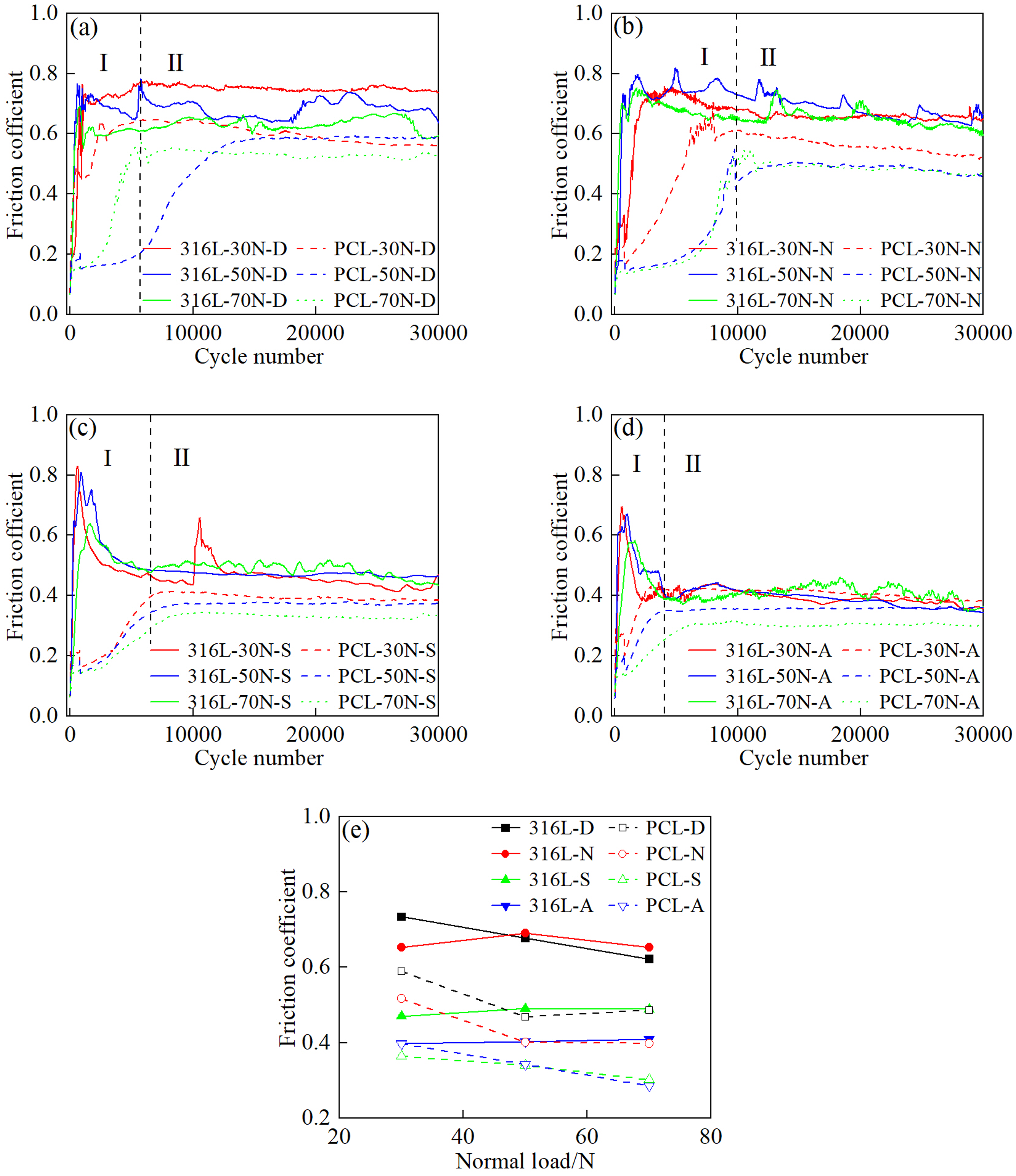
As illustrated in Figure 9, 316L showed a “V-W-U” pattern in these corrosive-lubricating solutions, while PCL displayed a U-shaped pattern. In distilled water and neutral solution, both 316L and PCL demonstrated slight plastic bulges at the edges of the wear scars. However, in acid rain and seawater, the edges of the wear scars showed more pronounced plastic bulges under higher loads. The lubrication effect of the solution and the high hardness of PCL reduced the adhesive and furrow effects, resulting in a more regular wear profile for 316L. GCr15/316L showed higher wear depths compared with GCr15/PCL in different corrosive solutions. In the four corrosive solutions mentioned above, the maximum wear depths of PCL did not exceed 5 μm. Because of the 25 μm thickness of PCL, the PCL remained intact in these corrosive-lubricating solutions, indicating that plasma carburization effectively protected 316L.
Wear profiles of PCL and 316L in distilled water at (a1) 30 N, (a2) 50 N, and (a3) 70 N; neutral solution at (b1) 30 N, (b2) 50 N, and (b3) 70 N; simulated seawater at (c1) 30 N, (c2) 50 N, and (c3) 70 N; simulated acid rain solution at (d1) 30 N, (d2) 50 N, and (d3) 70 N.
Under lower loads, the contact mode primarily involved point contact. Once the initial wear morphology was formed, the bottom of the wear pit was not subjected to repeated wear, resulting in a sharper V-shaped bottom. Adhesive wear occurred at the contact surface during this stage. Meanwhile, when severe adhesion occurred at the centre of the wear scar and the GCr15 ball encountered large debris particles within the wear scar, secondary material tearing and spalling occurred, resulting in the formation of a W-shaped pattern. Adhesive wear contributed to the peaks of the W-shape, while abrasive wear formed the valleys, which were directly associated with the stress state of the contact surface during the fretting process. Due to the corrosive effect and flow of the solution, the material at the contact surface was continuously detached, and abrasion developed in both the longitudinal and transverse directions. As the contact mode shifted from point contact to surface contact, debris accumulated in the central area. This accumulation altered the stress distribution, causing the central region to bear increased stress and preventing debris from being expelled. Consequently, plastic deformation and micro-cracking became more prevalent, and the accumulated debris intensified abrasive wear, ultimately forming a U-shaped pattern.
Wear resistance analysis
The wear resistance of 316L and PCL was determined from the wear rates and volumes obtained under different corrosive-lubricating solutions. The wear rate (K) can be calculated utilizing the mathematical expression below
58
:
In the same solution, the wear rate and wear volume of PCL and 316L both increased with an increase in the load. 316L experienced a higher increase in both wear rate and wear volume than PCL (Figure 10), attributed to the more significant material loss in the softer 316L due to mechanical wear.
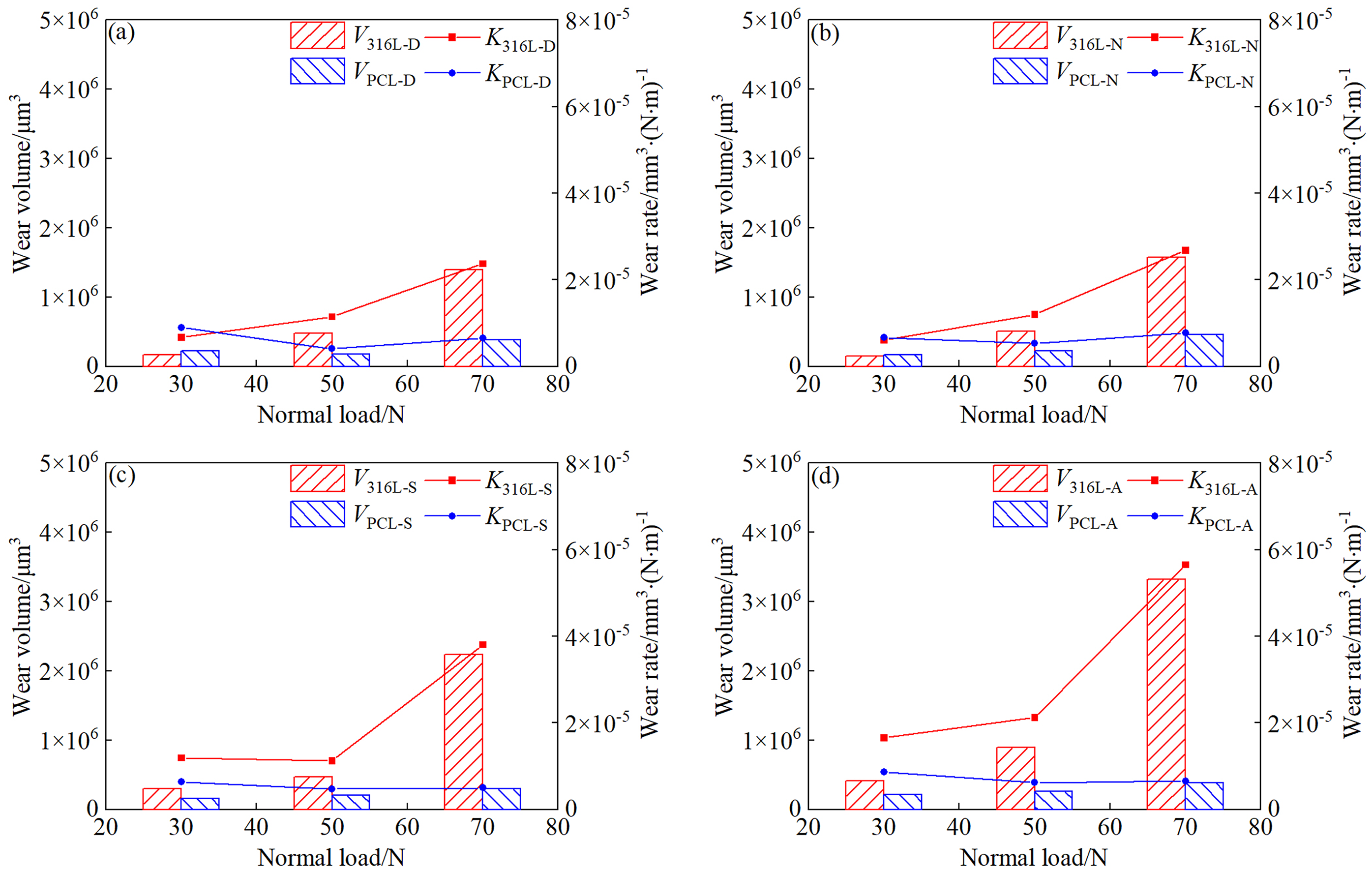
Wear rates and wear volumes of PCL and 316L in (a) distilled water, (b) neutral solution, (c) simulated seawater, and (d) simulated acid rain.
The wear rates and wear volumes of PCL and 316L in the four solutions followed the order: simulated acid rain > simulated seawater > neutral solution > distilled water (Figure 10). Fe, Cr, and Ni corrosion products were formed in the friction pairs immersed in seawater and acid rain due to the combined lubricating, anti-friction, and corrosive effects of these solutions. This increased the roughness of the contact surface, further intensifying wear. A significant amount of frictional heat was produced during the wear process. Although the continuous influx of the solution had a cooling effect, the presence of the solution also caused oxidation reactions at the interface, resulting in the generation of oxides. The GCr15 ball plowed through and fragmented the oxides and corrosion products, producing additional micro-protrusions on the contact surface and accelerating material loss. The observed wear volume in distilled water resulted from the interplay between lubrication and mechanical wear, as no corrosion effects were present. The acid rain contained a complex and abundant array of effective active anions
Fretting corrosion behaviour was affected by the different solutions under three different scenarios: (1) Distilled water, being non-corrosive, provided a passivation effect. It also offered lubricating and cooling properties, enabling it to withstand a certain degree of pressure and shear force. These characteristics altered the contact conditions and the actual contact area, leading to changes in the wear mechanism and wear volume. (2) The solution, being corrosive but lacking a passivation effect, altered the wear mechanism of the friction pair and influenced material loss. Also, more significant corrosion occurred in areas with defects and wear damage, leading to both corrosion and wear loss. The total wear volume was determined by the competing losses of solution lubrication and corrosion. (3) The solution had both corrosive and passivation effects (acid rain, seawater, and neutral solution). In addition to lubrication, cooling, and corrosion effects, a passivation film was formed between the contact surfaces. This passivation film could exist in two states: (i) When the passivation film was thick and demonstrated high load-bearing capacity, it provided both lubrication and protection, reducing wear. This effect persisted as long as the applied normal load remained insufficient to damage the film. (ii) When a thin, low-strength passivation film formed, it was prone to continuous destruction and repair, which contributed to additional wear. The total wear volume was determined by the combined effects of solution lubrication, corrosion, and the detachment of the passivation film. Under more severe friction conditions (heavy load, high speed, high temperature, and high frequency), more pronounced losses were achieved.
Cutting plasticity ratio and frictional energy dissipation coefficient
The wear scar morphology was examined to qualitatively analyze the deformation mechanism. Meanwhile, the cutting plasticity ratio (fcp) was employed to quantitatively evaluate the proportion of micro-cutting and micro-plowing in deformation, providing a more effective and accurate assessment of the deformation mechanism. The wear profile was simplified as shown in Figure 11(a).
59
The cutting plasticity ratio can be obtained via the mathematical relationship below
59
:
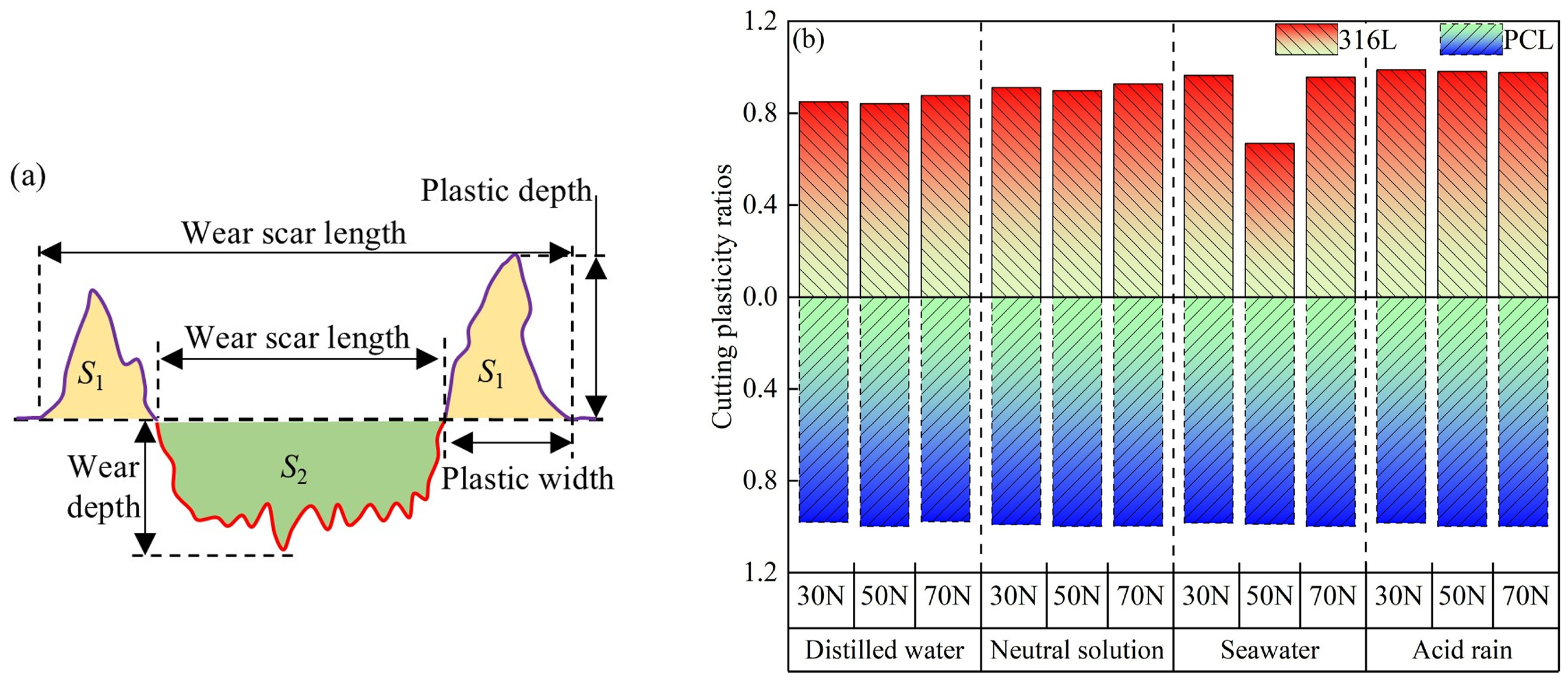
(a) Simplified wear contours of wear profile and (b) cutting plasticity ratios of 316L and PCL in different corrosive solutions.
The cutting plasticity ratio typically ranged from 0 to 1, indicating the competitive coupling of micro-plowing and micro-cutting. When the fcp value ranged from 0–0.5, material accumulation at the edges of the wear scar was more pronounced, suggesting that micro-plowing was the dominant wear mechanism. When the fcp value was in the range of 0.5–1, a greater amount of material was directly removed during the wear process, indicating that micro-cutting was the dominant wear mechanism. The penetration and movement of the GCr15 ball increased the slip and plastic deformation of the front material, leading to an increase in dislocation density and lattice distortion. Consequently, the material exhibited increased strength and hardness, resulting in work hardening. A portion of the material at the leading edge of the GCr15 ball accumulated along the wear scar boundaries due to micro-plowing, while the rest contributed to debris formation through micro-cutting. However, when the material adhesion effect was severe, the accumulation of abrasive debris at the wear scar edges (S1) exceeded the material loss due to wear (S2), potentially resulting in an fcp value below zero. 49
As depicted in Figure 11(b), the cutting plasticity ratio values of GCr15/316L and GCr15/PCL in the four solutions followed the following order: fcp−A > fcp−S > fcp−N > fcp−D, with fcp > 0.5. During fretting corrosion, material deformation simultaneously involved both micro-cutting and micro-plowing, with micro-cutting being the dominant mechanism. Micro-cutting generated debris within the wear scar, and some of this debris was expelled from the contact area. The remaining debris underwent migration, flattening, compaction, and high-temperature sintering due to the GCr15 ball, eventually contributing to adhesion, abrasive wear, and fatigue delamination. Micro-plowing generated grooves or trough-like features while causing the expelled debris to accumulate at the edges of the wear scar, leading to the formation of plastic bulges. Variations in pH values and solution densities, influenced by the types and concentrations of active ions, led to differences in corrosion wear, therefore causing slight variations in the cutting plasticity ratio.
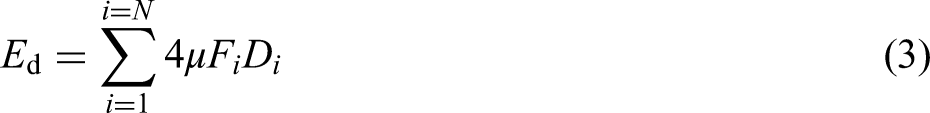
The frictional energy dissipation coefficient (αe) was utilized to assess the stability of the fretting corrosion processes of GCr15/PCL and GCr15/316L. As shown in Figure 12(a), the frictional energy dissipation (Ed) was quantified by the area enclosed within the tangential force-displacement amplitude curve (Ft-D). The shape and size of this area served as indicators for evaluating the wear state. Energy dissipation during the fretting wear process was indicated by the frictional energy dissipation coefficient.
60
The frictional energy dissipation coefficient can be calculated using the following formula
60
:

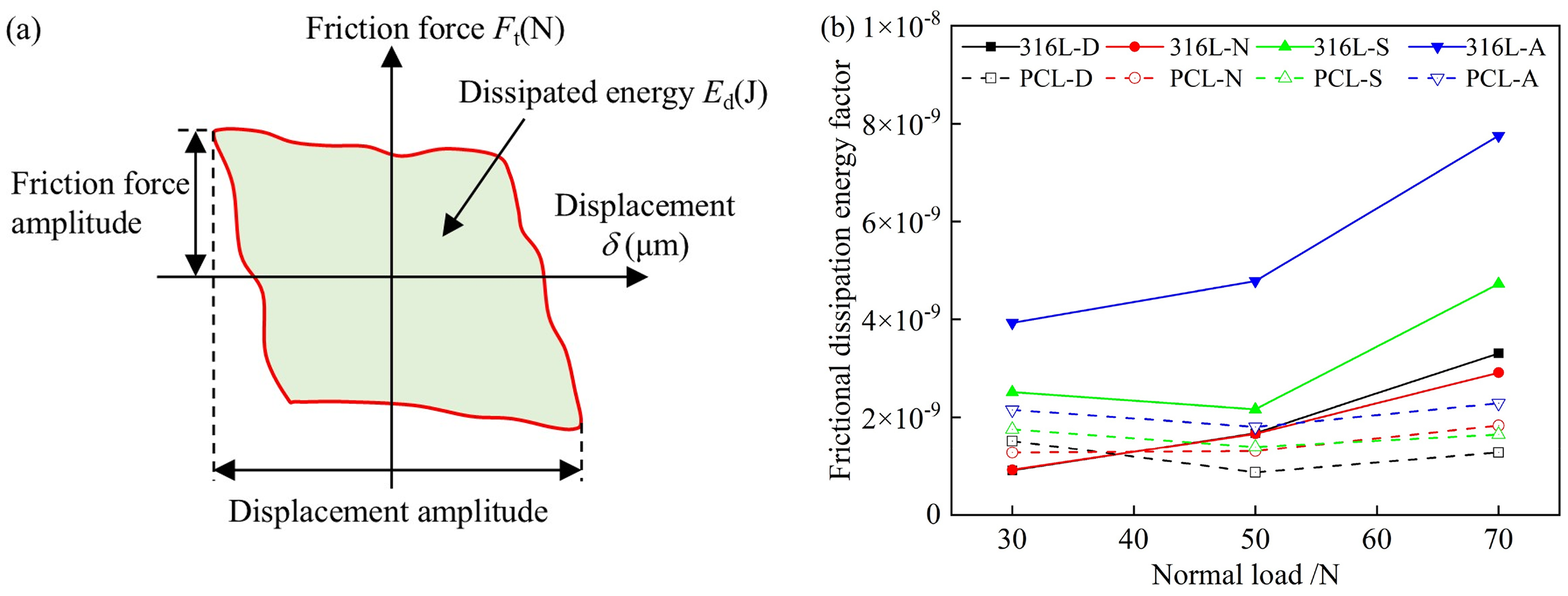
(a) A schematic diagram of the frictional dissipated energy and (b) frictional dissipation energy coefficient of PCL and 316L in various corrosive solutions.
The frictional energy dissipation coefficients of PCL and 316L followed the following order: αe−A > αe−S > αe−N > αe−D, as provided in Figure 12(b). The variations observed across different solutions were attributed to differences in their compositions and the concentrations of active anions. The complex and abundant active anion components in acid rain accelerated the formation and accumulation of corrosion products during the wear process. Compared to the other three solutions, the contact surface of each friction pair in acid rain was highly disordered, resulting in the highest frictional energy dissipation coefficient. As the load increased, the frictional energy dissipation coefficients of 316L and PCL also increased, with the coefficient for PCL being generally lower than that of 316L. Compared to 316L, plasma carburization increased the stability of the fretting corrosion process on PCL. The increased hardness and strength of PCL led to fretting corrosion dominated by elastic deformation in the GCr15/PCL contact, resulting in a lower frictional energy dissipation coefficient. The lower hardness and pronounced adhesion of 316L led to fretting corrosion in the GCr15/316L contact being primarily governed by plastic deformation, resulting in a higher frictional energy dissipation coefficient.6,7
The degradation of the passivation film due to fretting corrosion increased the number of micro-protrusions, facilitating the formation of grooves, cracks, and holes, which in turn intensified surface defects. The penetration of the solution into the contact surface facilitated the adsorption of active anions (Cl−, F−, Br−,
Discussion
Fretting corrosion mechanism analysis
The fretting corrosion mechanism of PCL and 316L within the corrosive-lubricating solutions could be categorized into three stages, as presented in Figure 13(a1)–(c2). (1) Initial friction stage. While undergoing a reciprocating radial motion, the GCr15 ball applied a downward force on the specimen, initiating the development of the wear morphology. At this stage, wear remained minimal; however, the maximum contact stress was reached. The contact mode involved micro-convex to micro-convex contact interactions in a two-body contact system between the GCr15 ball and 316L (PCL). The applied force from the upper specimen ball effectively facilitated the infiltration of the solution into the contact zone, actively influencing the wear dynamics. At this stage, neither corrosive nor oxidative wear was observed, with material removal primarily governed by mechanical wear (Figure 13(a1, a2)). (2) Critical transition stage. During the initial and intermediate stages of the fretting corrosion process, the influence of the solution and the increase in frictional temperature remained negligible, resulting in mechanical wear being the primary wear mechanism. The material underwent shear and compressive forces, experiencing “failure-spalling-refinement” to generate wear debris. In this stage, the wear process occurred via a “GCr15 ball-wear debris/316L (PCL)” arc-plane contact mode involving mixed two-body and three-body contact. The wear morphology exhibited small cracks, adhesion, plowing grooves, small wear pits, and plastic deformation. This stage was primarily characterized by mechanical wear, with slight contributions from oxidative and corrosive wear (Figure 13(b1, b2)). (3) Three-body contact stage. In the later stage of the fretting corrosion process, the corrosive action of the solution generated corrosion products at the interface. Simultaneously, the rise in friction temperature facilitated the formation of oxides, further influencing the wear mechanism. During this stage, the GCr15 ball exerted pressure on the detached material, corrosion products, and oxides, leading to their fragmentation, refinement, and compaction into a layer of wear debris. The agitation of the solution against the upper specimen caused some of the dispersed wear debris to form a suspension, resulting in “GCr15 ball-suspension/wear debris layer-316L (PCL)” three-body contact with a plane-plane contact mode. The combined effects of flow, lubrication, corrosion, and cooling from the solution smoothed shallow plowing grooves, micro-cracks, and pores, resulting in a relatively uniform wear morphology. The adhesion effect decreased, and the surface of the wear debris layer soaked in the solution experienced peeling and cracking. At this stage, the wear morphology exhibited plowing grooves, material spalling, large wear pits, and cracks. This stage was primarily characterized by mechanical wear, severe oxidative wear, and corrosive wear (Figure 13(c1, c2)).
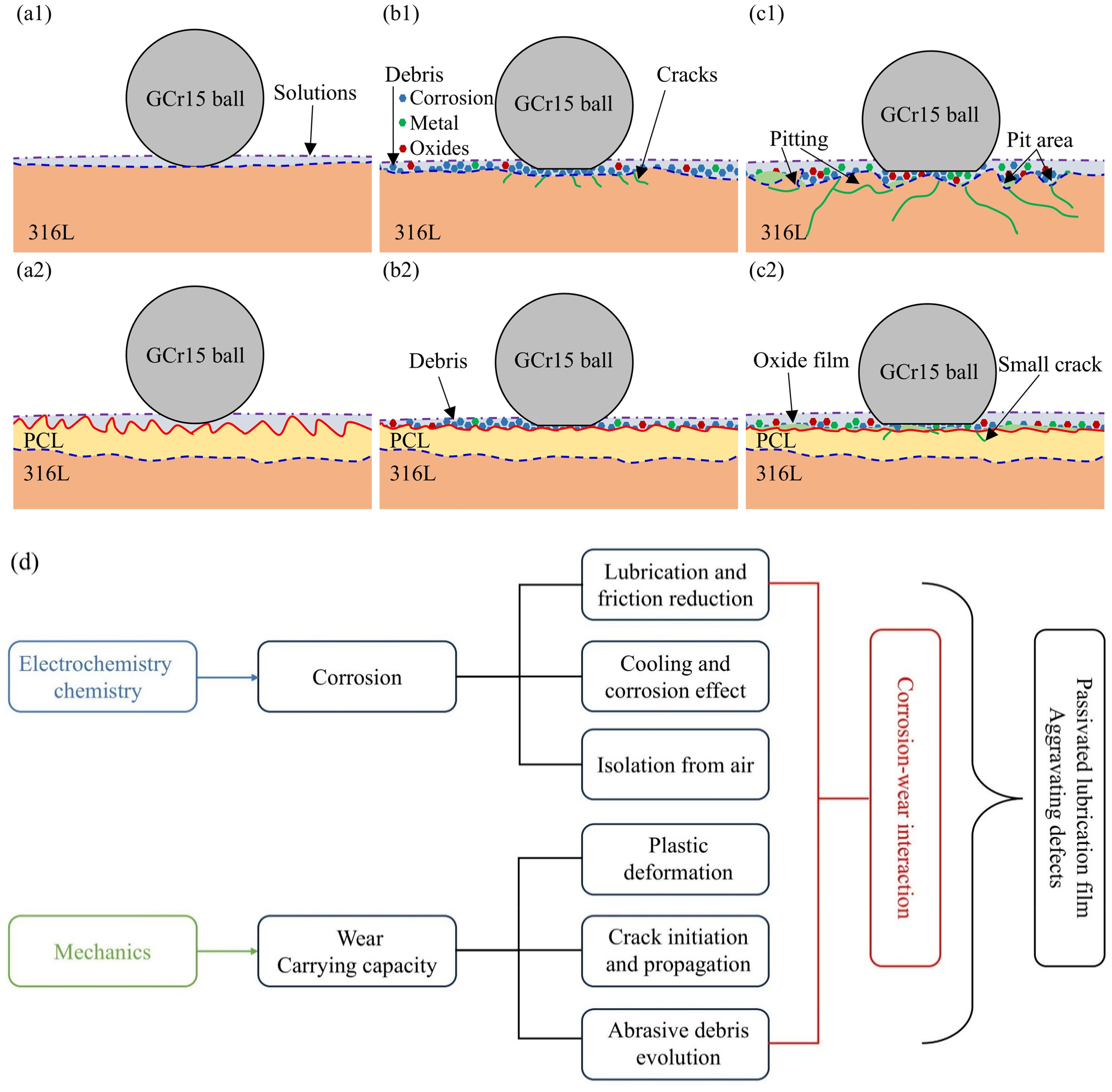
The fretting corrosion process at (a1) initial friction stage of 316L, (a2) initial friction stage of PCL, (b1) critical transition stage of 316L, (b2) critical transition stage of PCL, (c1) three-body contact stage of 316L, (c2) three-body contact stage of PCL. (d) The corrosion and wear mechanism of 316L and PCL.
A schematic diagram of the corrosion and wear mechanism of 316L and PCL in fretting corrosion is shown in Figure 13(d). The solution primarily affected the contact interface in four ways. (1) Lubrication and friction reduction. The solution isolated the upper and lower samples, restricting their direct contact. In this condition, the solution absorbed a portion of the contact stress, leading to a reduction in plastic deformation and the actual contact area. (2) Cooling effect. The continuous influx of the solution dissipated a portion of the heat generated during wear, thus lowering the interface temperature and preventing overheating of the friction pair. Consequently, adhesive wear slowed down. (3) Isolation from air. The solution isolated the substrate from the air, preventing reactions between the substrate and oxygen. The described phenomenon slowed down oxidative wear. (4) Corrosion effect. The corrosive nature of the solution resulted in the formation of corrosion products during wear, compromising the structural integrity and density of the material. Moreover, corrosion potentially damages the grain boundaries or phase boundaries of the materials, leading to an increase in the roughness of the interface and a reduction in material strength. Consequently, material loss increased, further intensifying wear. The mechanical effects on the contact interface primarily included two factors. 3 (1) Material in the contact area experienced plastic deformation, initiating and propagating cracks, which led to material flaking and transfer. (2) The formation, migration, refinement, and oxidation of wear debris were facilitated.
Combined Figure 2 and Figure 10 illustrated that as the Cl− concentration increased in corrosive solutions (neutral solution and simulated seawater), the combined effects of Cl− activity and frictional corrosion led to the formation of spalling, corrosion products, and pitting pits within the wear scars. These corrosion products served as lubricants at the contact interface, reducing the friction coefficient. Moreover, the viscosity and density of the corrosive solutions increased, and the contact interface produced a lubricating water film with a higher carrying capacity and lower friction coefficient. Compared with the low concentration of Cl− (neutral solution), the high concentration of Cl− (simulated seawater) showed better lubrication, cooling, and corrosion. In the absence of Cl− (distilled water), the passivation film effectively protected the material, preventing significant corrosive wear. Distilled water primarily provided lubrication and cooling effects, without inducing corrosion. In the presence of both Cl− and other active ions (simulated acid rain), the high reactivity and small ionic radius of Cl− enabled its preferential adsorption and disruption of the passivation film. This phenomenon led to spalling and pitting during fretting wear, forming additional pathways for other ions to penetrate, accelerating corrosion, and increasing material wear. Therefore, the friction coefficient followed the trend μD > μN > μS > μA while the wear amount displayed the trend (V, K)A > (V, K)S > (V, K)N > (V, K)D. Reactive ions exacerbated the corrosive-wear interaction, increased wear amount, and reduced friction coefficient.
Corrosion and wear interaction analysis
The losses caused by corrosion and wear were not simply the sum of wear loss and corrosion loss. Rather, it was influenced by the complex interplay between these two degradation mechanisms.
31
Various research studies reported the positive synergistic interaction between corrosive wear and mechanical wear on stainless steel, leading to significant material loss.9,61 Han
62
studied the corrosive wear of stainless steel in NaCl solutions, categorizing the synergistic effects of the corrosive wear process as antagonistic, synergistic, or additive-synergistic depending on the concentration of Cl−. M. Stemp
63
suggested that the corrosion of stainless steel in sulfuric acid solution was influenced by a negative synergistic interaction involving corrosion and wear. Studying the synergistic interaction of corrosive wear through a mathematical model is crucial for understanding and quantifying material degradation in corrosive environments.
64


Considering the lubrication and cooling effects of the solution, two methods are typically used to modify the model
53
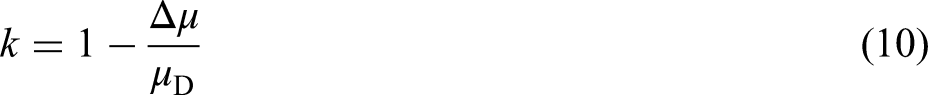
: (1) The wear volume measured under dry friction conditions is used as a reference to isolate the effect of pure mechanical wear, allowing for an assessment of the lubricating influence of solution. This mathematical model can be represented as
The third correction method was employed in this study to calculate the corrosive–wear interaction ratio (λ), with specific values detailed in Table 2. The mathematical model for corrosion–wear was further validated and expanded in its applicability. Because the losses caused by pure corrosion were minimal (Vc/V < 1%), they were excluded from Table 2. This paper focused on the mechanism of mechanical wear and corrosive-wear interaction.


Corrosion-wear related components and percentages of 316L and PCL in different corrosive solutions.
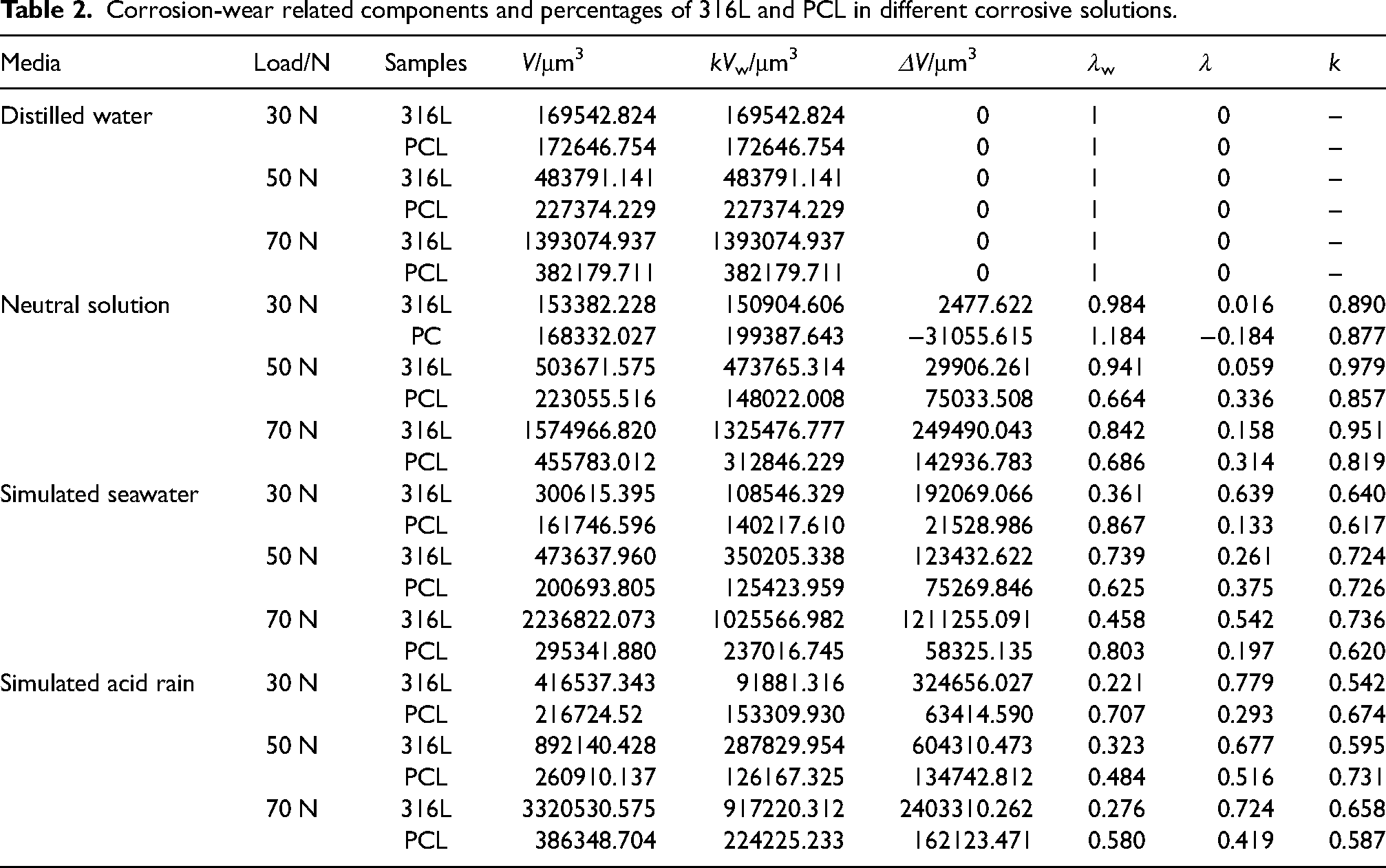
The material loss of 316L in simulated seawater resulted from the combined effects of mechanical wear and corrosive-wear interaction. The material loss of PCL was predominantly attributed to mechanical wear, contributing to more than 60% of the material loss. In simulated acid rain, the material losses of 316L and PCL were caused by both corrosive-wear interaction and mechanical wear, with the corrosive-wear interaction accounting for over 70% and 50% of material loss, respectively. The material losses of 316L and PCL in neutral solution resulted from both corrosive-wear interaction and mechanical wear. However, mechanical wear was the predominant factor in 316L material loss, contributing to over 80% of the total degradation.
With increasing load, the corrosive-wear interaction ratio of PCL in neutral solution shifted from negative suppression to positive synergistic interaction, accounting for over 30% of the material loss. This observation suggests that the influence of corrosive-wear interaction on PCL became more pronounced as the applied load increased. At a load of 30 N in neutral solution, PCL demonstrated a negative corrosive–wear interaction because of the minimal corrosiveness of the solution. Under this lower load, the neutral solution mainly functioned as a lubricant and coolant, resulting in a reduced wear volume (V = 168332.027 μm³) than the dry wear volume in the air (V = 425180.146 μm³). 51 Mechanical wear significantly contributed to material loss in neutral solution. Owing to the purely lubricating properties and low conductivity of distilled water, the corrosive–wear interaction ratios for both 316L and PCL remained negligible. Consequently, material loss in distilled water was exclusively governed by mechanical wear. In summary, the proposed mathematical model effectively quantifies the corrosion–wear interactions of 316L and PCL across various environments, including simulated seawater, simulated acid rain, neutral solution, and distilled water.
The formation of corrosion pathways and corrosion products was reduced by the high hardness, uniform density, and minimal defects of the ion carburizing layer, leading to significant mechanical wear. The carburized layer presented three main advantages in corrosive solutions36,51: (1) improved passivation of 316L, (2) formation of an expanded austenite (Sc) phase, which effectively minimized intergranular corrosion and pitting, and (3) increased surface hardness and strength, increasing load-bearing capacity and refining the grain structure. The higher grain boundaries and sub-grain boundaries significantly restricted dislocation movement, improving the fatigue and wear resistance of the carburized layer.
The corrosive-wear interaction typically resulted in a reciprocal enhancement between corrosion and wear,61,65,66 which occurred in two keyways: (1) Wear promoted corrosion. The wear process disrupted the passivation film and removed corrosion products, exposing fresh metal to further wear. This fresh metal formed “large cathode-small anode” micro-galvanic cells with intact parts of the passivation film, leading to the initiation and development of pitting corrosion. Moreover, wear increased the roughness of the interface, leading to plastic deformation and work hardening. Consequently, a high density of dislocations and localized residual stress concentration developed, increasing internal energy and enhancing chemical reactivity. Wear-induced micro-cracks, pores, and material flaking led to a higher density of defects, including dislocations, vacancies, and cracks. These localized defects, characterized by high disorder and increased corrosion activity, functioned as anodes, whereas the surrounding regions with lower chemical activity served as cathodes. The interaction between these anodes and cathodes generated a “strain differential battery”, facilitating the development of corrosion pathways and accelerating the overall corrosion process. The reciprocating motion of the GCr15 ball, in conjunction with the solution's confinement, induced localized oxygen concentration gradients at the interface. The observed variation facilitated the establishment of differential aeration cells, enhancing the cathodic depolarization process and accelerating localized corrosion. 28 (2) Corrosion accelerated wear. Localized areas of high chemical corrosion activity at the interface acted as anodes, whereas intact and relatively smooth areas served as cathodes. This electrochemical heterogeneity promoted the formation of micro-galvanic cells, facilitating preferential corrosion and accelerating material degradation. The porous and loosely adhered corrosion products were readily removed by mechanical wear or flushed away by the solution, compromising the structural integrity and density of the interfacial material. The described process potentially damaged the grain boundaries and phase boundaries of the material, increased the roughness of the interface, reduced the material strength, and accelerated material loss and wear damage.
Conclusions
The fretting corrosion behaviour of 316L and PCL were effectively investigated in simulated seawater, simulated acid rain, neutral solution, and distilled water. The conclusions can be written as follows:
The friction coefficients of 316L and PCL in various solutions exhibited the following trend μD > μN > μS > μA, while the wear rate, cutting plasticity ratio, and frictional energy dissipation coefficient followed the reverse order. In neutral solution and distilled water, 316L and PCL showed fatigue peeling and adhesive wear. In seawater and acid rain, 316L showed fatigue peeling, adhesive, and corrosive wear. PCL demonstrated adhesive wear and corrosive wear. The wear profile of 316L exhibited a “W-V-M” pattern, whereas PCL demonstrated a U-shaped pattern. PCL showed a relatively low wear rate, wear depth, and frictional energy dissipation coefficient compared to 316L. PCL significantly enhanced the fretting corrosion stability and wear resistance of 316L and had a remarkable protective effect on 316L. In seawater and acid rain, the material losses of 316L and PCL resulted from the combined effects of mechanical wear and corrosive-wear interaction. In neutral solution and distilled water, the material losses were governed by mechanical action, accompanied by slight corrosion-wear interaction. The corrosive-lubricating solutions intensified the corrosive-wear synergistic interaction.
Footnotes
Author contribution(s)
Declaration of conflicting interests
The authors declared no potential conflicts of interest with respect to the research, authorship, and/or publication of this article.
Funding
The authors disclosed receipt of the following financial support for the research, authorship, and/or publication of this article: This work was supported by the the Key Science and Technology Project of Gansu Province, China, Science and Technology Project of Wenzhou City, China, Major Science and Technology Project of Gansu Province, China, (grant number No. 20YF8GA058, No. ZG20211003, No. 22ZD6GA008).