
Abstract
This study investigates the impact of heat treatments on the microstructure and mechanical properties of Inconel 718 components fabricated by Laser Powder Bed Fusion (LPBF). To address residual stresses and microstructural inhomogeneities caused by rapid thermal cycles, three sequential treatments homogenization heat treatment (HHT), solution heat treatment (SHT), and aging heat treatment (AHT) were applied. Using a multi-objective Response Surface Method (RSM), heat treatment parameters were optimized. HHT was conducted at 1080 °C for 1–8 h, followed by SHT (980–1140 °C for 1 h) and standard AHT. Results revealed that a 2-h HHT led to optimal mechanical performance and a refined, uniform microstructure by redistributing Nb and Ti precipitates from the γ-matrix, enhancing the alloy's strength and service capability.
Keywords
Introduction
Nickel-based superalloys such as Inconel 718 (IN718) are widely employed in aerospace applications, including turbine blades and compressor casings, due to their excellent mechanical strength, creep resistance, and corrosion resistance at elevated temperatures up to 650 °C. 1 These components often require complex geometries and must endure demanding service conditions. Traditional manufacturing techniques struggle to meet these evolving design and performance requirements, prompting a shift toward advanced fabrication technologies.
Additive manufacturing (AM), particularly LPBF also referred to as Direct Metal Laser Sintering (DMLS) has emerged as a powerful technique for producing intricate metal parts layer by layer with near-full density.2,3 LPBF offers precise dimensional control, robust surface quality, 4 and mechanical properties that can surpass those of conventionally manufactured counterparts.5,6 This process is compatible with various metal alloys, including stainless steel, 7 Ti-6Al-4 V, 8 and notably, IN718,9,10 making it a promising approach for fabricating high-performance aerospace components.
In polycrystalline materials, the term texture refers to the preferred crystallographic orientation of grains. This characteristic becomes particularly significant in materials fabricated through additive manufacturing processes such as LPBF, where rapid solidification and directional heat flow can lead to the development of strong texture. Since texture influences various anisotropic properties such as mechanical strength, corrosion resistance, and thermal conductivity it is important to consider its evolution and effects when evaluating the performance of LPBF-processed components.11,12 However, during LPBF, the repeated rapid heating and cooling cycles induce high levels of internal stress in the components. As a result, post-process thermal treatments are often necessary to achieve a uniform microstructure, reduce internal stresses, and obtain the desired mechanical properties.13,14 One important feature of LPBF IN718 is the directional solidification resulting from specific heat transfer patterns in the build orientation. Heat flows from the laser-concentrated top layer of the powder bed toward the build plate. 15 This causes significant temperature gradients, leading to anisotropic properties due to the formation of a pronounced material texture. In addition, variability in mechanical properties has been observed across different LPBF machines. This variability is influenced by factors such as part orientation during fabrication and the laser scan strategy used. 16 The columnar grain structure with strong fiber texture that LPBF produces can enhance creep resistance in some applications, such as turbine blades and disks.17,18
However, many applications require a microstructure with fine, equiaxed grains to improve strength, fatigue performance, resistance to intergranular crack growth, and achieve isotropic mechanical properties. 19 The formation of microscopic dendritic structures is associated with high-temperature gradients (G) and rapid solidification rates (R). This results in columnar or equiaxed/cellular morphologies depending on the G/R ratio20–22. These dendrites often align with a high density of dislocations at cell boundaries, reinforcing the material through dislocation and Hall-Petch strengthening mechanisms. Despite ongoing research, achieving a fully uniform grain structure and consistent texture in LPBF IN718 components through process parameter optimization remains challenging.1,23,24 Adjusting scanning strategies or laser power without careful optimization risks defects such as voids, incomplete fusion, and poor substrate wetting. 25 Recrystallization, achieved through heat treatment, is essential to eliminate the as-built columnar microstructure and improve mechanical uniformity across parts, making them more comparable to wrought IN718. 16
Most research on heat treatments for LPBF IN718 focuses on optimizing the alloy's microstructure and mechanical properties by controlling precipitate formation and dispersing undesirable phases formed during the LPBF process. However, less attention has been given to grain growth and texture evolution during thermal processing, even though these factors significantly impact the mechanical performance of LPBF IN718 components.
Following the HHT and SHT procedures, the fish-scale formations in IN718 transformed into sophisticated columnar crystal microstructures. The treated samples achieved an ultimate tensile strength of 1396 MPa, with an elongation of 24%. 26 The mechanical properties of alloys are influenced by various microstructural factors, including grain size, precipitate size and distribution, and strain hardening. Additionally, as Bunge et al. 27 emphasizes, the distribution of crystal orientations within the grain boundaries significantly affects mechanical performance, as plastic deformation depends on the angular separation between slip systems and the direction of applied stress. 28 Despite the use of standard thermal treatment processes for nickel alloys, notable anisotropy in mechanical properties was observed. 29 Extensive studies have shown that the standard thermal treatment conditions, designed for both cast and wrought IN718, do not eliminate the textured and columnar structures typical of the LPBF process24,28–30. Thus, modified HHT and SHT conditions are required to achieve additively manufactured parts with homogeneous mechanical properties and uniform microstructures similar to those found in wrought alloys. In addition to standard treatments, various modified thermal treatment conditions have been investigated to optimize the microstructure and mechanical properties of LPBF-manufactured IN718. 31 It was observed that SHT at 1000 °C resulted in the highest mechanical performance, due to the increased volumetric ratio of γ’ and γ'‘ phases and the absence of the δ-phase, compared to SHT930 and SHT954 conditions. 31 However, despite SHT930, SHT954, and SHT1000 treatments, the as-built texture and grain structure remained unchanged because these temperatures were below the recrystallization threshold. 31
Further studies explored the effects of SHT temperatures ranging from 980 °C to 1280 °C on the microstructure and mechanical properties of LPBF IN718, aiming to identify optimal SHT conditions. 32 The findings indicate that increasing SHT temperature from 980 °C to 1230 °C for 1 h promoted greater dissolution of the Laves phase, achieving a homogeneous structure at 1080 °C for 1 h. Full recrystallization was achieved after SHT at 1130 °C for 1 h. 32 However, temperatures exceeding 1080 °C for 1 h led to a reduction in mechanical properties, revealing a trade-off between optimizing mechanical characteristics and achieving full recrystallization.32,33 Transforming the as-built columnar microstructure into an equiaxed microstructure through recrystallization not only promotes isotropic mechanical properties but also introduces grain boundary interfaces, which improve mechanical performance. The presence of annealed twin interfaces enhances room-temperature mechanical properties in IN718. 34 Furthermore, these twin boundary interfaces act as barriers to dislocation movement, enhancing creep resistance at elevated temperatures. 35 It is widely recognized that recrystallization, initiated by selecting appropriate heat treatments, facilitates the transition from columnar to equiaxed grain structures. 34 A persistent challenge with the LPBF-processed IN718 alloy is the trade-off between achieving high mechanical properties and obtaining a fine equiaxed microstructure with minimal texture. 35 Consequently, this study aims to identify heat treatment conditions that optimize a balance between these properties, offering an effective solution to enhance the alloy's performance.
This investigation aims to optimize post-process heat treatment strategies for LPBF-fabricated IN718, focusing on achieving superior mechanical properties. It explores the effects of combined HHT durations and SHT temperatures on grain structures, crystallographic texture, and mechanical characteristics. The optimal thermal treatments were identified using a multi-objective optimization process (Response Surface Methodology, RSM). Moreover, the study examines the impact of the proposed treatment conditions on the microstructure, hardness at ambient temperature, and tensile strength at 650 °C for thermally treated LPBF IN718 alloy.
Experimental procedure
Materials and LPBF process
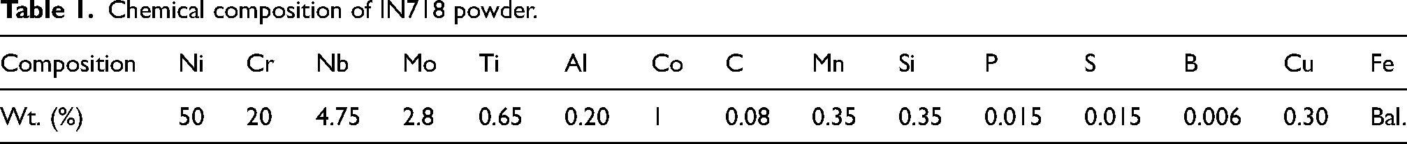
The gas-atomized IN718 powder, which complies with the specified chemistry requirements, was selected. Most of the raw IN718 powder particles exhibit a smooth spherical shape. The distribution of spherical powder size was determined from the SEM micrographs (Figure 1(a)) utilizing the ImageJ software. According to the statistical findings, the mean particle size is 20.10 μm, ranging from 4 μm to 40 μm, as depicted in Figure 1(b). The results of X-ray diffraction (XRD) analysis for IN718 powders are illustrated in Figure 1(c). The main phase constitutions of the powders can be inferred to include the (111), (200), (220), and (311) planes of the γ (Ni-Cr-Fe) phase, which exhibit a face-centered cubic lattice. 36 The composition, as provided by the seller (EOS GmbH, Munich, Germany), is presented in Table 1.
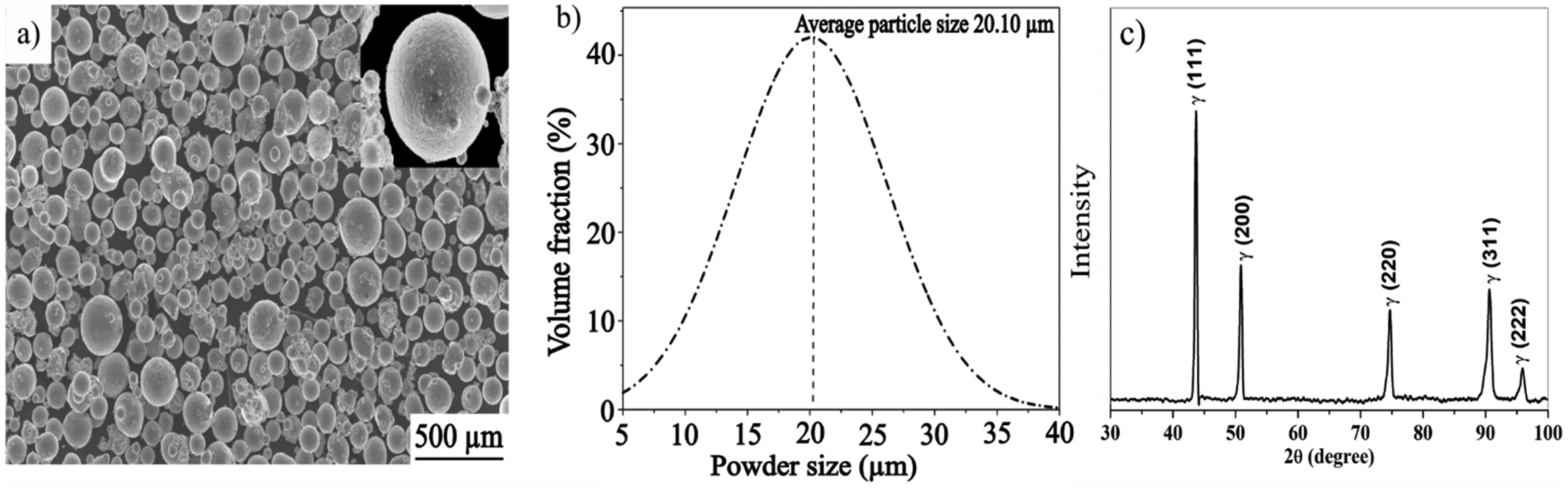
(a) SEM image of IN718 powders (b) Particle size distribution (c) XRD results of the IN718 powders.
Chemical composition of IN718 powder.
The additive manufacturing process for the samples was conducted using an EOS M280 direct metal laser sintering (DMLS) machine, manufactured by EOS GmbH in Munich, Germany, which is outfitted with a laser capable of delivering up to 400 watts of power. The standard fabrication parameters used are given in Table 2. The LPBF build plate was pre-heated to 100 °C, and the fabrication process was carried out in a pure argon environment. Two sets of samples were manufactured in the horizontal build orientation for mechanical properties and microstructure analysis. The tensile test sample using EOS M280 LPBF as per ASTM E08 standard 37 and for hardness and microstructural analysis, rectangular cuboid samples (15 mm*10 mm*3 mm) were prepared as illustrated in Figure 2. Materialise Magics software was employed for file preparation. Wire EDM was employed to remove the specimen from the build plate, and no thermal condition for stress relief was administered to maintain the as-built structure.
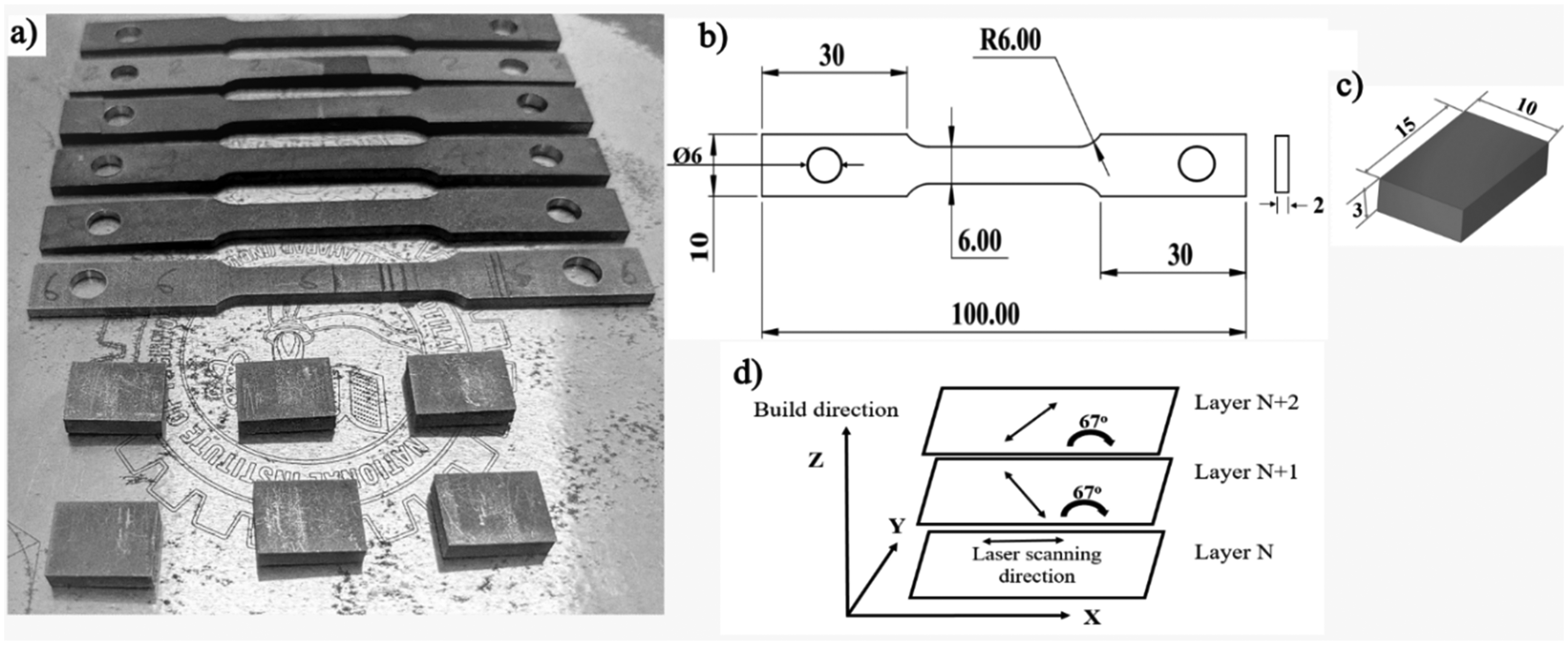
(a) Final parts for the tensile test, hardness test and microstructural analysis (b, c) schematic diagram of LPBF-manufactured specimens (d) schematic diagram of the scanning strategy.
LPBF IN718 standard fabrication parameters.
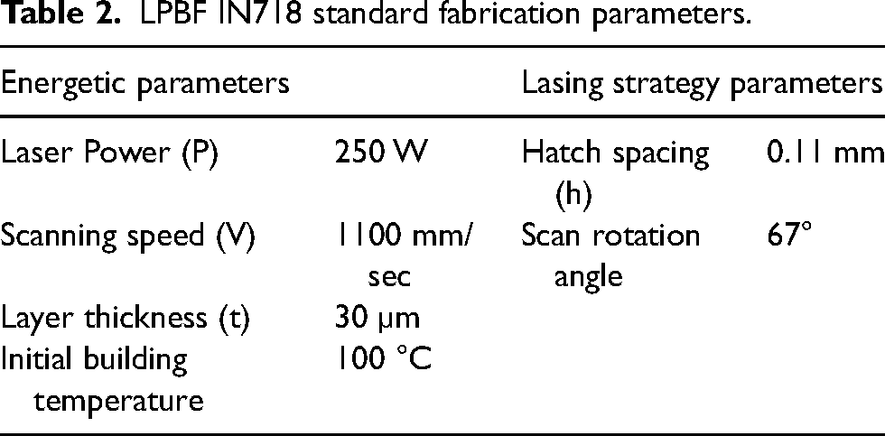
The volumetric energy density (VED) varies based on process parameters, as described by equation (1).
38

Heat treatments
To assess the impact of HHT and SHT durations on the high-temperature tensile characteristics of LPBF IN718, a series of five distinct conditions was established, as illustrated in Table 3.
The sample identification and heat treatment conditions. FC furnace cooling, AC air cooling, WC water cooling.
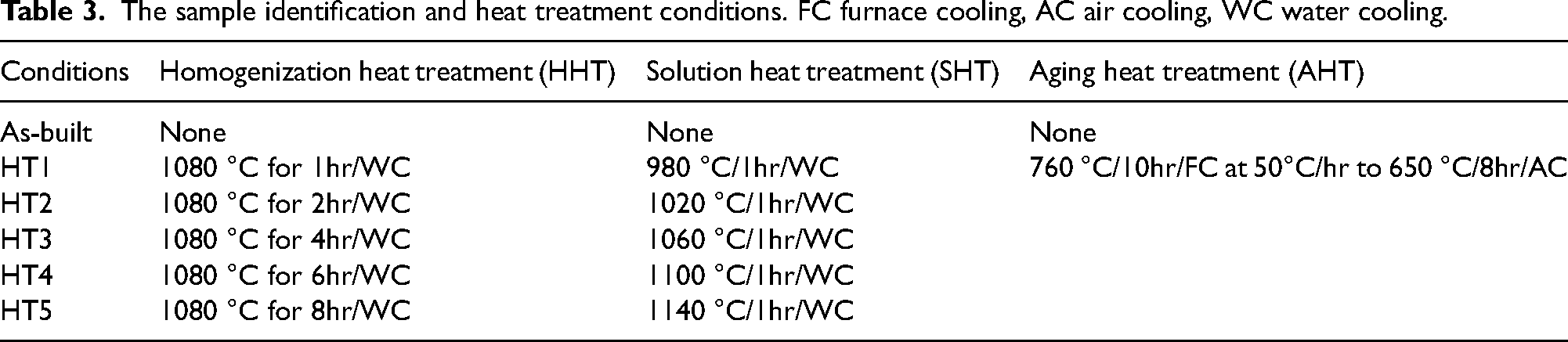
Table 3 provides the designations and specific information for the five different heat treatment conditions used in the experiment. The heat-treatment processes were carried out in an electric muffle furnace (Model: VSMF 1400V2), with K-type thermocouples to observe temperature variations of the IN718 specimen throughout the heat-treatment process.
To determine the optimal thermal treatments and comprehend the impact of the interaction between HHT durations and SHT temperatures on microstructure and mechanical characteristics, employed a design of experiment method using Design-Expert 13 software. 39 Information regarding the optimization parameter and the suggested treatments are elaborated upon in Section 3.1.
Mechanical properties and characterization
The primary purpose of the IN718 alloy is to manufacture components intended for elevated-temperature applications. Tensile testing for both the as-built and thermally treated samples at a temperature of 650 °C was carried out using an INSTRON 100 kN (Model: MTS-610) test setup with a strain rate of 10<συπ>−3 </συπ>per second, which was fitted with an infrared heating oven as illustrated in Figure 3. K-type thermocouples are used to observe temperature variations across the gauge length throughout the testing process. After failure, an external argon flow was promptly introduced to facilitate the rapid cooling of the IN718 test samples down to room temperature. Vickers hardness testing (model: RMHT-201) for both the as-built and thermally treated samples with a 1 kg load and a dwell time of 10 s was conducted. To ensure precision in the results, a minimum of 10 evenly distributed measurements were carried out for each condition. All indentations have been executed on the XY-section of the specimens.
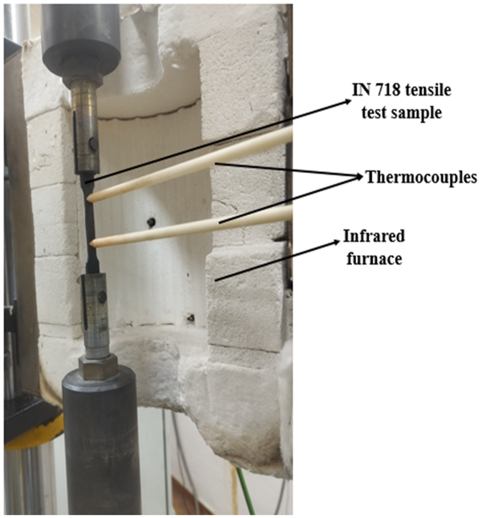
Setup for conducting tensile tests at high temperatures (650 °C).
The microstructures of IN718 were examined in both as-deposited and heat-treated states using a Joel JXA-8230 field emission scanning electron microscope (FESEM). This microscope was outfitted with an an Oxford AZtecHKL electron backscatter diffraction (EBSD) system for analyzing grain structures. The changes in grain size and shape distribution were investigated through EBSD analysis, employing an operating voltage of 20 kV with an Image resolution of 1.63 μm, for both as-built and various heat treatments. For each condition, the total mapping area was set at 1290 × 975 μm² to ensure coverage of the maximum number of grains. The samples underwent a preparation process: first, 800 to 2000 grit SiC paper was used, followed by diamond suspensions containing particles of a specific size of 3 to 4 μm, and finally, colloidal silica with a particle size of 0.02 μm. All samples were electrochemically polished for surface preparation before EBSD analysis. Phase identification and transformation were examined using an X-ray diffraction (XRD) under both the as-built and thermally-treated samples. The analysis was performed by Rigaku Ultima IV 3 kW diffractoscope with a scanning increment of 0.02° within the 2θ ranges of 30° to 125°.
Results and discussion
Multi-objective optimization using RSM
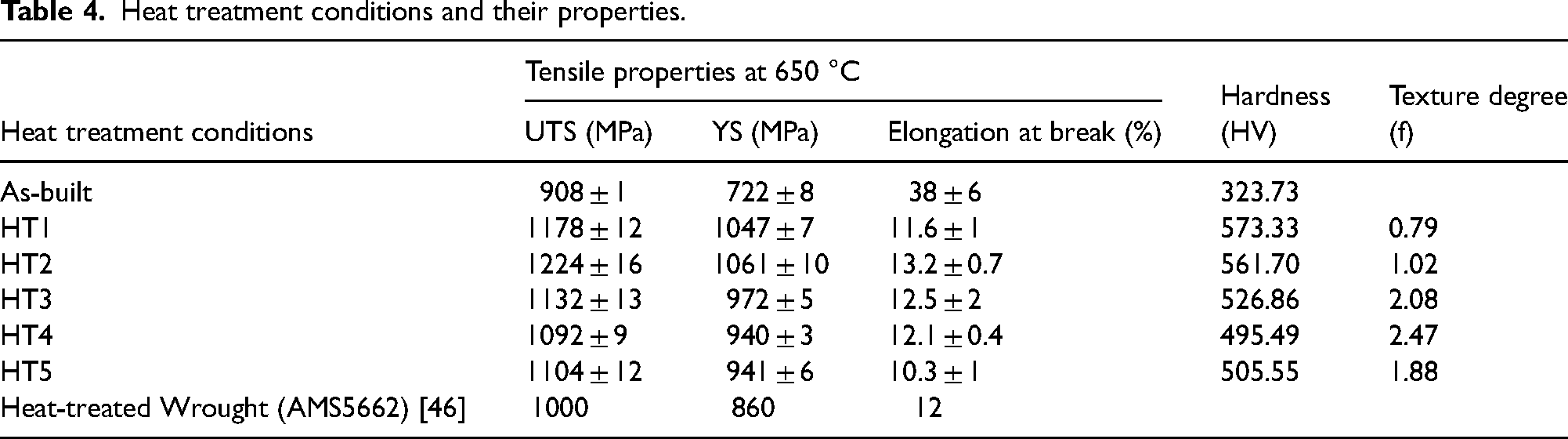
Response Surface Methodology (RSM) was employed as a statistical tool for the multi-objective optimization of the LPBF process, aiming to simultaneously enhance key mechanical properties ultimate tensile strength (UTS), yield strength (YS), elongation to break, and hardness while maintaining the texture degree within a desired range. Given that industrial applications often demand concurrent optimization of multiple mechanical characteristics to fulfill diverse functional requirements, a desirability function approach was used to combine individual response objectives into a single composite metric. This approach enabled a balanced trade-off among potentially competing goals and facilitated a comprehensive exploration of the process design space. Specifically, the optimization considered both process parameters and post-processing heat treatment conditions (as outlined in Table 3), with their respective responses presented in Table 4. These data were used to generate response surface diagrams, thereby providing deeper insights into how various processing factors influence the mechanical behavior and crystallographic texture of the LPBF-fabricated components. The RSM optimization diagrams depicting the progression of tensile characteristics of LPBF IN718 superalloy at 650 °C (UTS, YS, elongation at break), room temperature Vickers hardness (HV), and texture degree (f) were represented in Figure 4. These were plotted as functions of the HHT time and SHT temperature, utilizing Design-Expert 13 software. 39
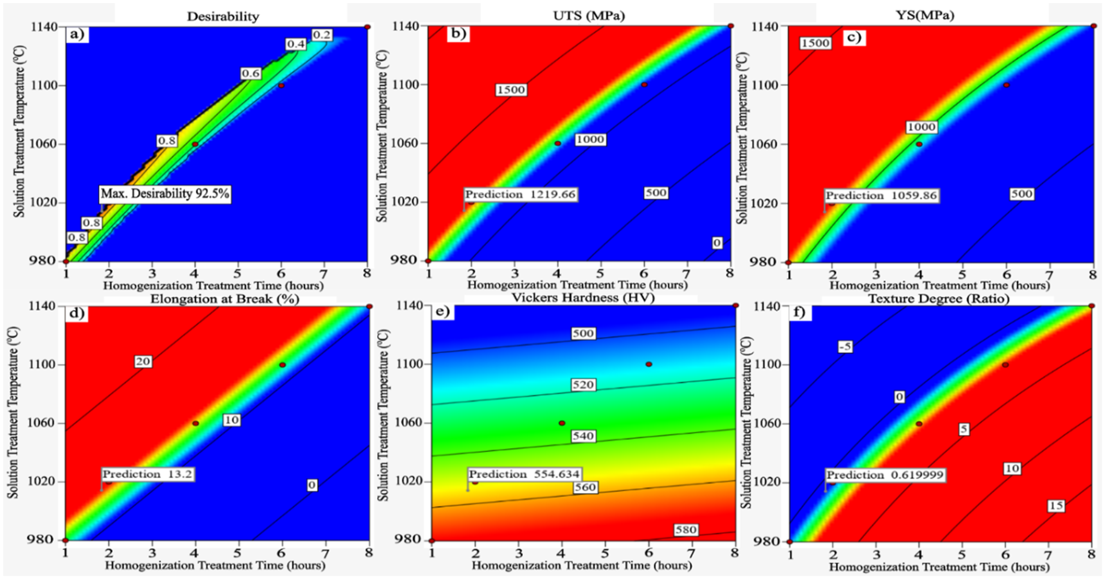
Contour line graphs (a) maximum desirability (b) predicted values of UTS (c) predicted values of YS (d) predicted values of elongation at break (e) predicted values of hardness value (f) predicted values of texture degree.
Heat treatment conditions and their properties.
The material texture's degree under the thermal treatments is determined by the intensity ratio f, as documented in.
40
This ratio is to be expressed as:
Whereas I(111) and I(200) are the maximum intensities of the (111) and (200) planes acquired from the X-ray diffraction study.
Utilizing the results mentioned above, a multiobjective optimization was performed to determine the optimal HHT durations and SHT temperatures that can meet designated objectives for all findings. The optimization parameter and target utilized are elaborated upon in Table 5.
Information regarding the target and criteria for multi-objective optimization.
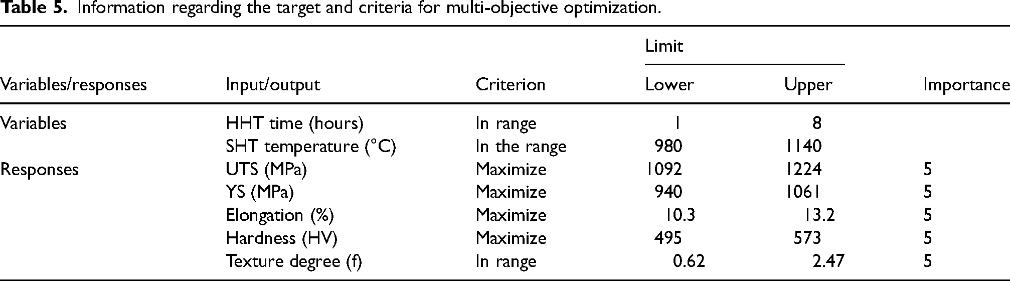
A multi-objective optimization was performed by applying an objective function known as “desirability,” with values ranging from 0 (indicating the least preferred outcome) to 1 (representing the optimal target obtained). As indicated in Table 5, all responses were assigned the same importance level, 5. Concerning the response criteria, as shown in Table 4, the optimization objective for UTS, YS, elongation at break, and hardness responses was set to “maximize”. However, for the texture degree, the target chosen was “in range”. The latter criteria preserve solutions that correspond to the higher intensity ratios of
The analysis reveals that the maximum desirability value of approximately 92.5% is achieved within a narrow processing window, specifically under HHT conditions of 1080 °C for 2 h and SHT at 1020 °C for 1 h, both followed by water quenching. This indicates an optimal combination of mechanical performance and structural characteristics. Figure 4(b)–(f) displays the predicted outcomes of the individual properties under varying processing conditions. Notably, changes in HHT duration and SHT temperatures, exert a significant influence on the mechanical responses. As illustrated in Figure 4(b) and 4(c), both UTS and YS attain their peak values (1219.66 MPa and 1059.86 MPa, respectively) within the optimal region. However, a progressive decline in strength is observed as the HHT duration extends beyond 2 h, indicating a detrimental effect likely caused by microstructural coarsening or over-aging. Similarly, Figure 4(d) shows that elongation at break also reaches a maximum predicted value of 13.2% within the same optimal region, suggesting a favorable balance between strength and ductility. This ductility decreases with prolonged heat treatment, potentially due to the onset of grain growth or changes in phase morphology. The Vickers hardness contour (Figure 4(e)) mirrors these trends, with a peak value of 554.63 HV achieved at the optimal conditions. This consistent pattern across multiple mechanical properties highlights the sensitivity of the alloy's performance to processing duration. Figure 4(f) illustrates the texture degree variation, where the optimal zone is associated with a lower predicted texture ratio (0.619), indicative of a more randomized grain orientation and, hence, more isotropic behavior. Increasing the HHT time tends to increase the texture intensity, possibly introducing anisotropy into the material. The 2 h HHT conditions markedly enhanced the mechanical performance of the LPBF IN718 superalloy at 650 °C. However, its influence on the texture analysis and grain microstructure was found to be minimal.
Phase identification using x-ray diffraction
XRD evaluation was utilized as a primary characterization and screening technique due to its ability to offer rapid and insightful feedback regarding the microstructural changes, including alterations in texture and the occurrence of phase precipitation/dissolution. These aspects are pivotal considerations in the optimization method. Figure 5(a) displays the X-ray diffraction spectra of both the as-built and thermally-treated specimens.
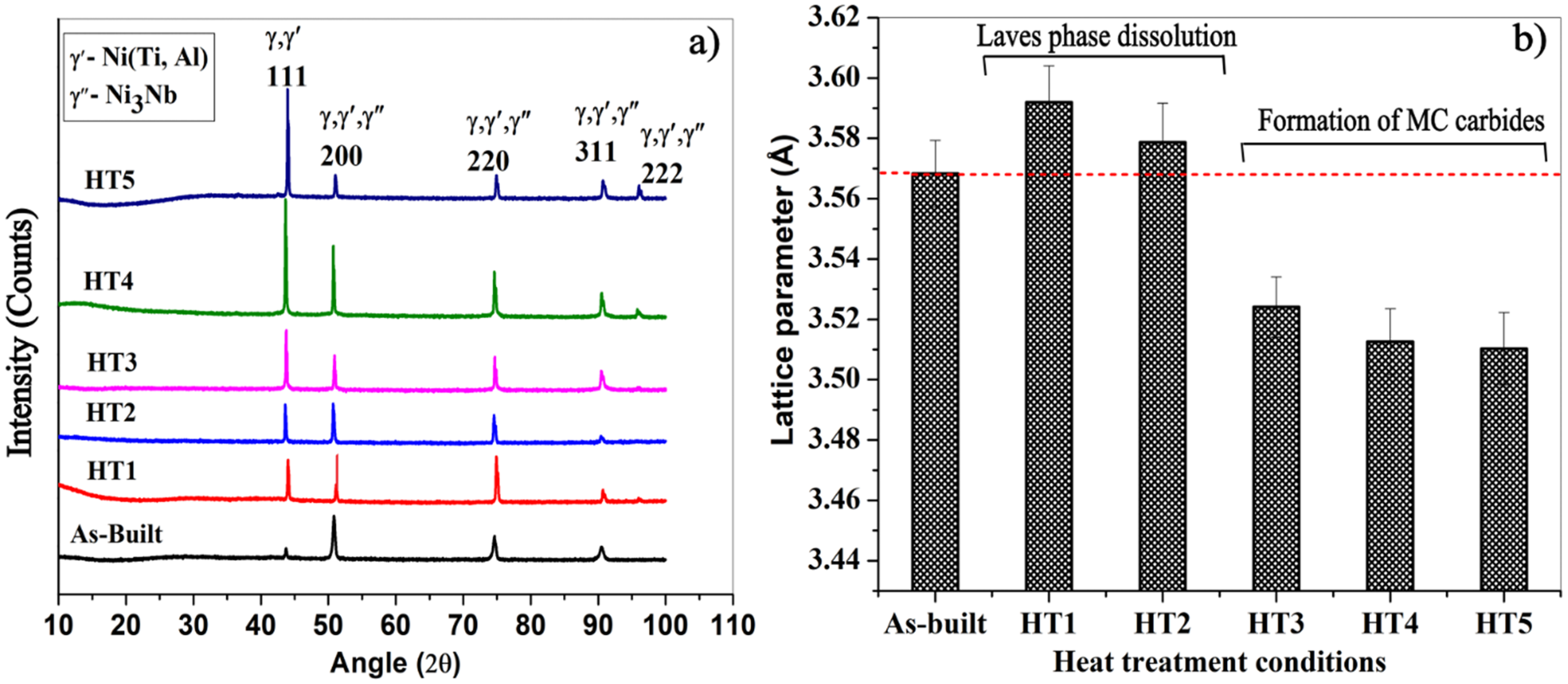
(a) XRD analysis for both the as-built and heat-treated conditions of LPBF IN718 (b) Lattice parameter evolution of the as-built and heat-treatment conditions.
As evident from Figure 5(a), both the as-built and HT1 treatments displayed greater peak intensities of γ (200) compared to γ (111). This suggests that the HT1 condition did not substantially alter the texture of the as-built material, possibly because of inadequate activation energy. Nevertheless, extending the HHT duration to 2, 4, 6, and 8 h led to observable alterations in the texture of the as-built LPBF IN718. This extension showed greater peak intensities of γ (111) in comparison to γ (200), as indicated by the intensity ratios (f) illustrated in Table 4. This indicates that following an HHT at 1080 °C for 2 h, the texture of the as-built sample was already notably influenced by the duration of HHT. Moreover, the formation and dissolving of phases contained Nb, Ti, and Mo, the crystallographic parameter of the γ-matrix in thermally-processed specimens (HT1, HT2, HT3, HT4, HT5) was determined, as illustrated in Figure 5(b). To compare, the lattice parameter of the γ-matrix in both the as-built and thermally-processed conditions is shown in this figure, depicted by a dashed line. As observed, the crystallographic parameter of the γ-matrix in the as-built state elevated from 3.5683 ± 0.0021 Å to 3.5920 ± 0.0028 Å after HT1, 3.5787 ± 0.0014 Å after HT2, treatments. This phenomenon can be associated with the dissipation of segregation of Nb, Ti, and Mo back into the γ-matrix. The process of back-diffusion has a positive effect on the strength characteristics of the LPBF IN718 superalloy. This facilitates the release of more age-hardening elements like Nb and Ti, those essential for the formation of γ’ and γ” phases. Nevertheless, the lattice parameter of the γ-matrix relative to the as-built state decreased to 3.5241 ± 0.0010 Å, 3.5126 ± 0.0032 Å, and 3.5103 ± 0.0017 Å after HT3, HT4, and HT5, respectively. It is notable that the lattice parameter gradually reduces as the HHT time increases to 4, 6, and 8 h. This phenomenon can be attributed to the reduction of certain alloying elements (such as Nb and Ti) within the γ-matrix during the heat treatment process. Thus, it is anticipated that there will be a decline in the mechanical properties following the HT3, HT4, and HT5 heat treatments because of the reduced formation of γ׳ and γ״ phases. Jiang et al. 43 also reported a reduction in the lattice parameter of the γ-matrix with longer annealing treatments. Thus, it may be inferred that the HHT at 1080 °C for 2 h (HT2) marks a threshold beyond which the decline in strengthening is attributed to a reduction in precipitation-inducing elements.
Microstructural evolution
Figure 6 displays the distribution of precipitates in both the as-printed and heat-treated states. As depicted in the microstructure of the as-built state (Figure 6(a)), there are chain-like formations of segregated compounds in small regions and laves phase present at the interdendritic and grain boundaries.
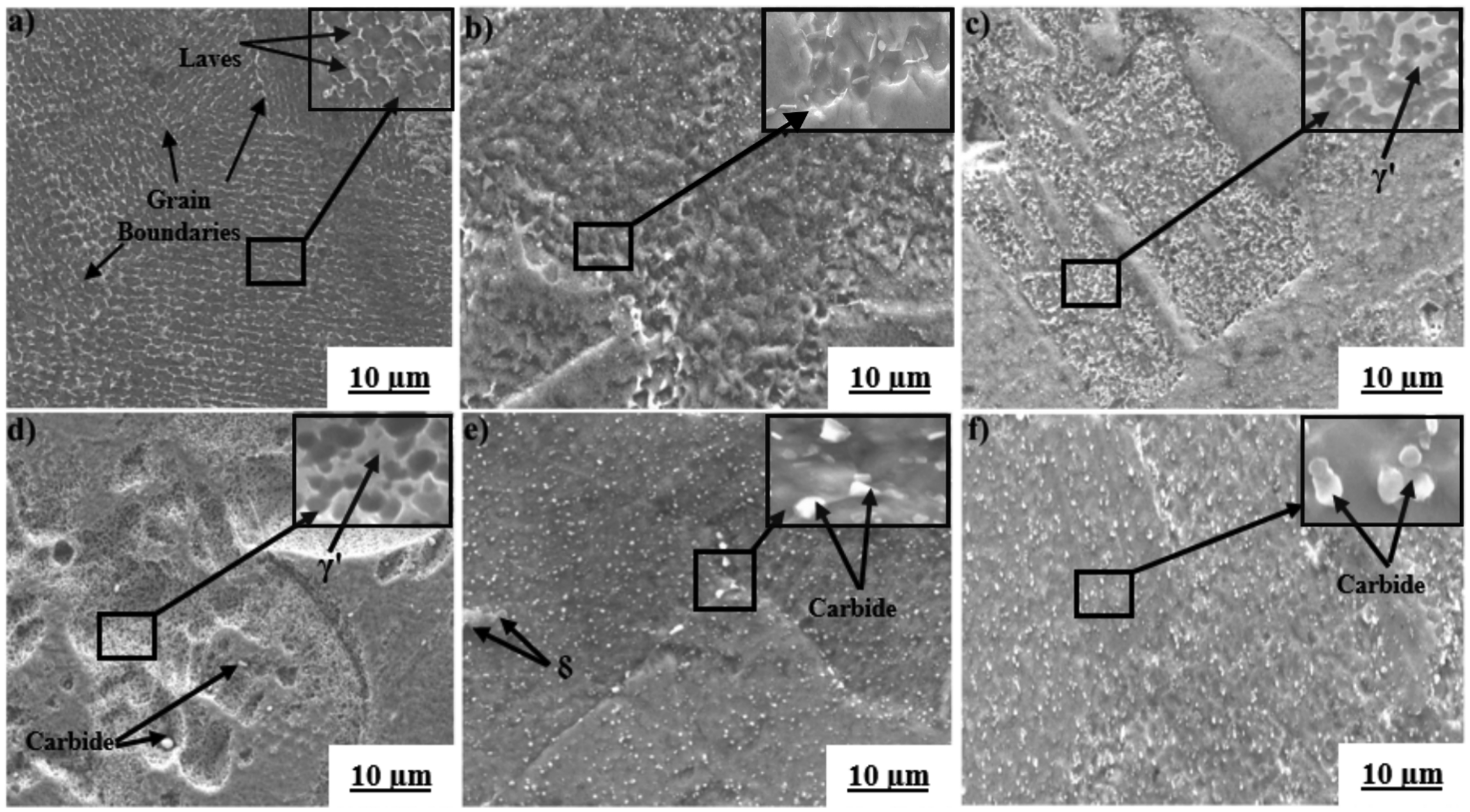
SEM micrographs of the LPBF-fabricated IN718 (a) As-built (b) HT1 (c) HT2 (d) HT3 (e) HT4 (f) HT5.
The EDS spot investigation conducted on the dendrite indicates the presence of enriched Nb and Ti compositions alongside a reduction in Ni, Fe, and Cr on the dendrite periphery, in contrast to the composition of the γ-matrix (as depicted in Table 6).
EDS spot analysis of the heat treatments as shown in figure 6 (weight %).
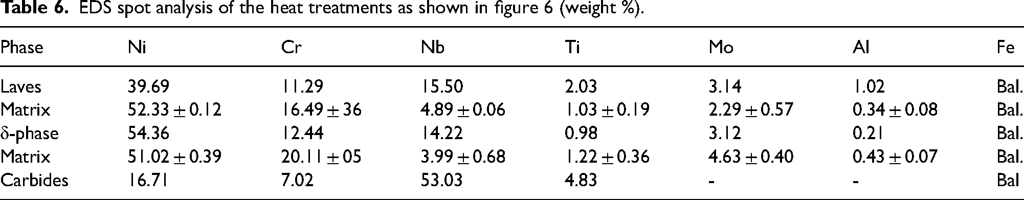
The purpose of the HHT at 1080 °C is to disperse the dispersed constituents and undesirable phases, for instance, the Laves phase, while after SHT aims to precipitate the δ-phase. Following heat treatments with varying HHT durations (1, 3, 4, 6, and 8 h), the chains of interdendritic and grain boundary Laves phase were dispersed, facilitating a more extensive distribution of segregated elements into the γ-matrix, as depicted in Figs. 6(b) to 6(f). Moreover, intergranular δ-phase formed subsequent to the heat treatment conditions, suggesting an almost total dissolution of the Nb-enriched areas within the grains. Towards the completion of the solidification stage, there was a greater accumulation of segregated elements along grain boundaries in comparison with the interdendritic regions, which had an increased amount of Nb. This occurs due to the fact that the affinity energy of Nb along grain boundary interfaces is twice that within the matrix.44,45 Throughout the HHT, the interdendritic precipitates readily disappeared, while maintaining ample Nb content at the grain boundary interfaces for the subsequent formation of intergranular δ-phase during the SHT. Following the HT3, HT4, and HT5 treatments, a greater number of unevenly shaped particles appeared at the grain boundaries, as illustrated in the inset images of Figure 6(d-(f)). Based on the EDS evaluation depicted in Figure 6(e), it is evident that these particles exhibit significant enrichment in Nb (≈ 68 wt. %) and Ti (≈ 8.18 wt.%), leading to their classification as MC carbides. The observations align with outcomes of the γ-matrix lattice parameter evaluation, revealing a reduction in the lattice parameter of the γ-matrix. This reduction can be attributed to the dissipation of Nb and Ti within the matrix, leading to the formation of MC carbides. As depicted in Figure 6(b) and 6(c), the microstructure following the 1-h and 2-h HHT conditions primarily consists of numerous elongated grains, with a minority of equiaxed grains distributed predominantly at the grain boundary interfaces of the enlarged grains. Therefore, it is anticipated that the mechanical characteristics of LPBF IN718 will remain anisotropic even following the HT1 and HT2 conditions. While the primary objective of the HHT is to disperse the segregations and achieve a homogeneous distribution of elements within the γ-matrix, this may induce steady-state recrystallization. This process is essential for refining the as-built structure, thereby enhancing the mechanical characteristics of LPBF IN718. As previously described, the majority of relevant literature focuses on methods to homogenize the as-built microstructure and enhance mechanical characteristics by dissolving detrimental phases and precipitating strengthening phases such as γ׳ and γ״. Nevertheless, comparatively lower emphasis is placed on understanding the grain microstructure, which is crucial for achieving isotropic mechanical properties, particularly given the typical lengthened grain structure of the as-built LPBF IN718. Comparable conclusive remarks are also present in pertinent reference.46,47
Microtexture and grain structure analysis
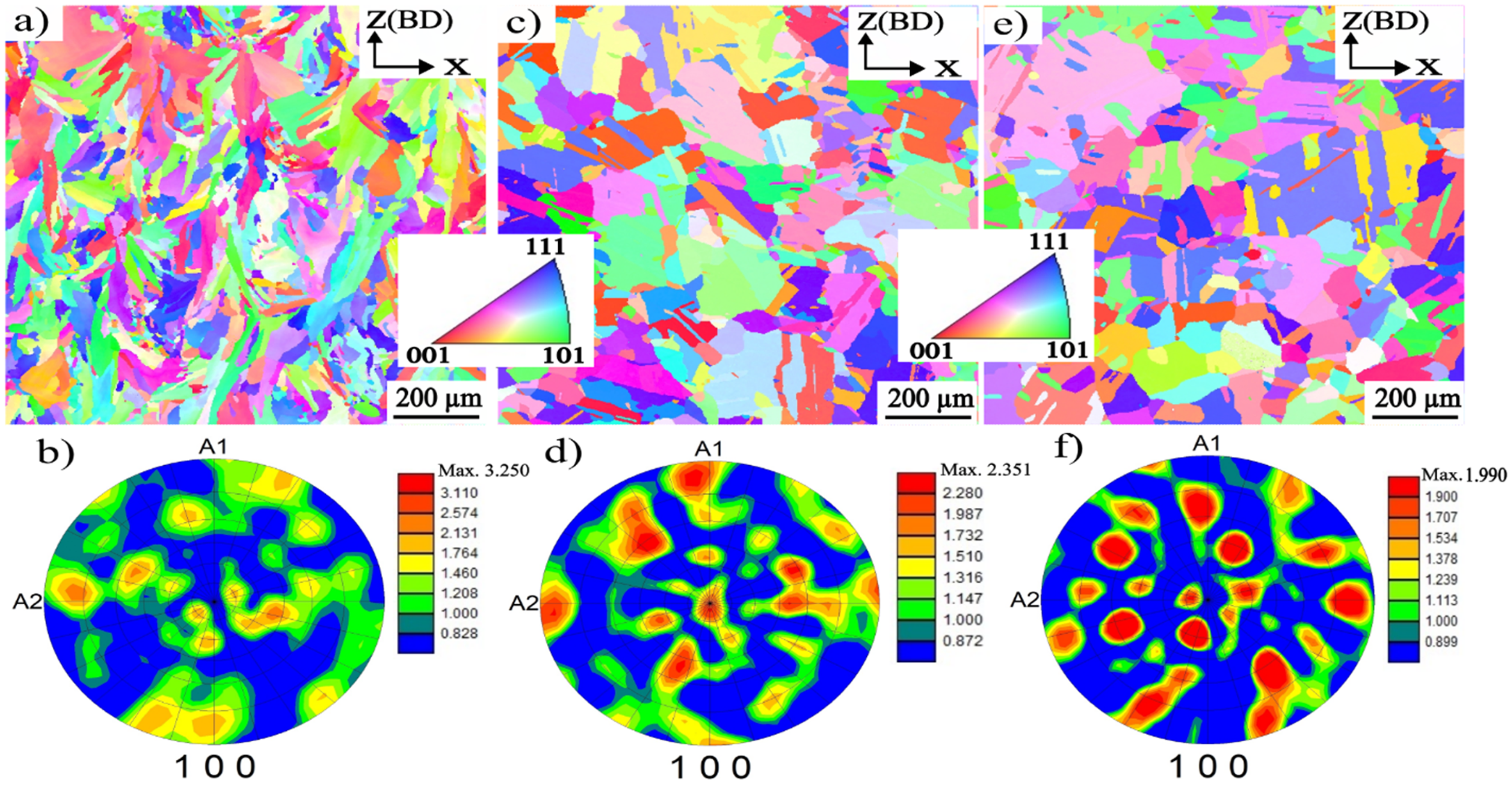
Figure 7 displays the inverse pole figures (IPF) and pole figures (PF) of the as-built and thermal treatments, which are employed to examine the changes in the grain crystal microstructure. The X-ray diffraction and grain structure evaluations guided the selection of HT2 and HT5 treatments for further examination with EBSD. This choice was made because HT2 treatments mark the threshold at which the reduction in precipitation-strengthening components (Nb and Ti) from the matrix begins, whereas HT5 conditions signify the point at which nearly fully recrystallized material is achieved. As illustrated in Figure 7(a, (b)), the as-built state of LPBF IN718 displays an enlarged grain structure with a robust fibrous texture, where the (100) plane is aligned along the build orientation. Following the HT2 conditions, significant alterations in crystallographic orientation are evident, as illustrated in Figure 7(c), with a reduced texture intensity value of the maximum uniform density along the (100) plane in the PF, depicted as 2.351 in Figure 7(d). This indicates a weakening of the (100) texture in comparison with the as-built state, where the maximum uniform density was 3.250. These findings align with those obtained from the XRD analysis, as illustrated in Figure 5(a). Comparable conclusive remarks are also present in pertinent reference. 48
EBSD analysis
Figure 8(a-(f)) presents the grain aspect ratio histograms for the as-built, and heat-treated conditions, obtained from the electron backscatter diffraction analysis. The aspect ratio mentioned in Figure 8 refers to the ratio of grain width to length. This ratio is close to 1, the grains are more equiaxial. As depicted in Figure 8, the histogram intensities of the as-built, HT1 and HT2 treatments are closer to the smaller aspect ratio. This suggests that a considerable number of columnar grains remain following the HT2 thermal treatment. Following the HT3 to HT5 condition, complete recrystallization of equiaxial grains with annealed twins was obtained, becoming the predominant grain structure. In this stage of full recrystallization, a comparatively weakened texture is evident, with a maximum uniform density of 1.99 along the (100) plane (Figure 7(f)). Additionally, the alignment of the grain map measurements shows lower alignment with the (100) plane in comparison with HT2 and as-built states. Moreover, a notable rise in the aspect ratio of the grain microstructure is observed for the HT3 to HT5 treatments (Figure 8(d)-(f)). This is highlighted by the peak shifting towards greater aspect ratios, indicating the formation of newly equiaxial grains through the full recrystallization process. Similar conclusive remarks can also be found in the relevant references. 47
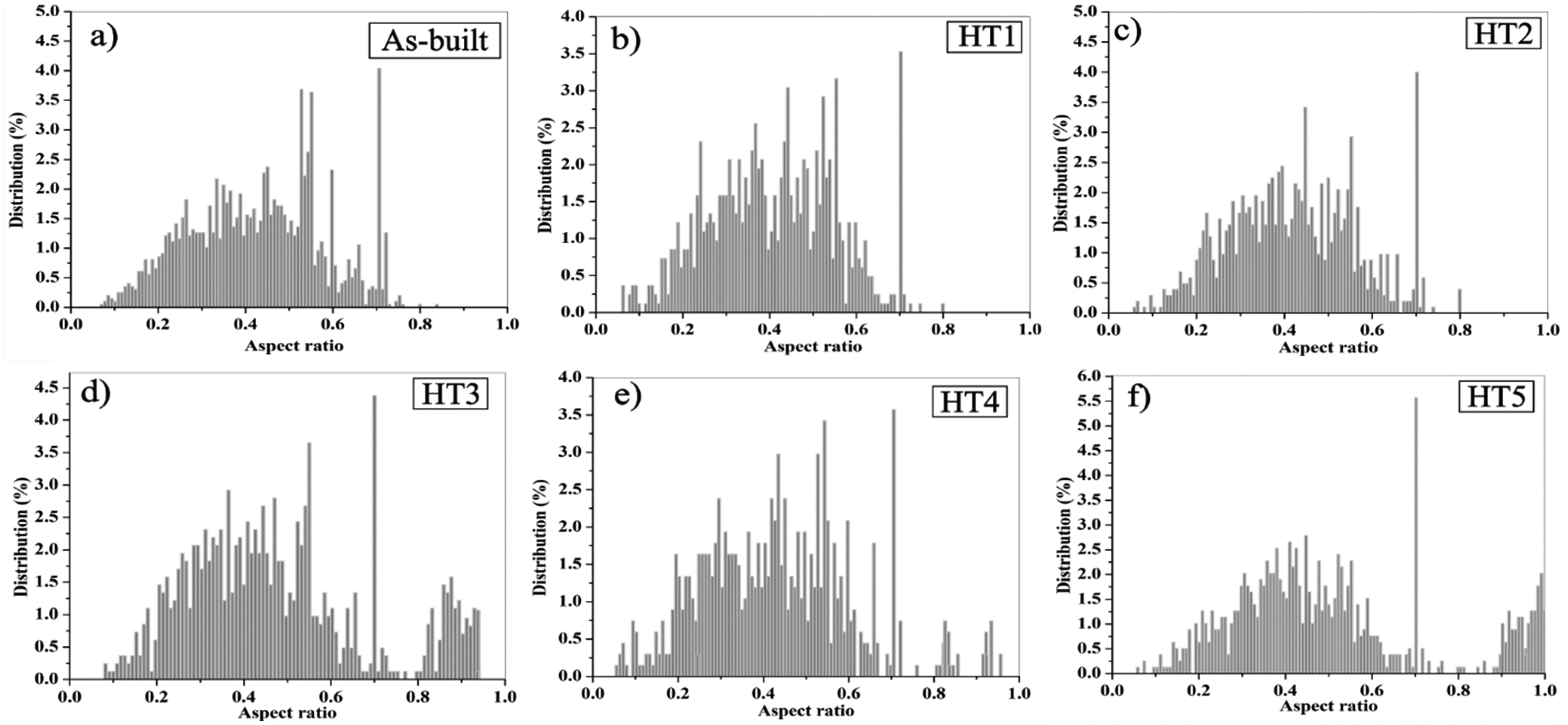
Grain aspect ratio (a) as-built (b) HT1 (c) HT2 (d) HT3 (e) HT4 (f) HT5.
Misorientation angle evolution
The development of a crystallographic orientation tangle throughout the LPBF solid-state transformation, and its changes under various heat treatment conditions, significantly influence the mechanical characteristics of IN718.
In this context, Figure 9 illustrates the progression of high-angle grain boundaries (HAGBs, the misorientation larger than 15°, blue lines) and low-angle grain boundaries (LAGBs, the misorientation ranging from 2° to 15°, red lines) of the IN718 superalloy under both the as-built and thermal treatments. The range of misorientation angles between 0° to 2° was not considered significant in our EBSD data processing, in line with common practice to minimize noise-related artifacts. 49 As depicted in Figure 9(a), the microstructure in the as-built state comprises columnar grains, characterized by a comparatively dense presence of low-angle grain boundaries with a number fraction (NF) of 38.61%. Following the HT2 condition, there is a slight decrease in the density of LAGBs to 32.27%, which aligns with the grain structure observations, since the majority of the structure shows (such as columnar dendrites) vanish in the microscopic images. Moreover, the transition of certain columnar grains into equiaxial grains (inadequate recrystallization) additionally leads to a small elevation in high-angle grain boundaries, from 58.36% to 69.89%, at the expense of low-angle grain boundaries, as illustrated in Figure 9(d). Following the HT5 treatment, there is a notable reduction in LAGBs, declining from 37.8% to 3.54%. Conversely, HAGBs experience an increase from 69.89% to 92.07%, as demonstrated in Figure 9(c, (d)). This phenomenon can be attributed to the significant reduction of sub-grain features: complete recrystallization is attained following the HT5 condition, evidenced by the significant presence of annealed twins.
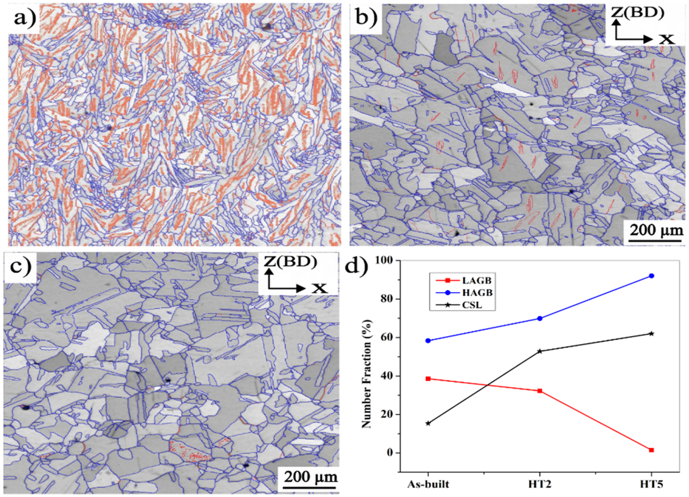
Grain boundary and misorientation angle distribution of
For the HAGBs, grain boundary interfaces with small coincidence site lattice (CSL) values (1 < Σ ≤ 29) are typically referred to as “special” grain boundary interfaces, as they contain minimal crystal defects. 50 Additionally, the CSL parameter is commonly employed to analyze grain boundary character distribution (GBCD) and to identify twin boundaries. The existence of twinned structures, like coherent CSL Σ3, usually alters the energy and mobility of a mobile interface, 51 consequently impacting various material properties. Primary twins, known as CSL Σ3, are identified by a 60° misorientation around the (111) plane, and they can form throughout heat treatments/recrystallization processes. To further monitor the occurrence of annealed twins post-thermal treatment conditions, the presence of the NF for CSL Σ3 grain boundary interfaces in both as-built and thermal treatments was examined, as illustrated in Figure 9(d). In this figure, it is noteworthy that compared to the conditions of as-built and HT2, the HT5 treatment exhibits a relatively higher NF (62.01%) of CSL Σ3 grain boundary interfaces, attributed to the abundance of annealing twins. The emergence of the newly annealed twin boundary interfaces can occur because of the interaction of established CSL Σ3 boundary interfaces during grain boundary migration/growth anomalies at migrating grain boundary interfaces.
It is significant to observe that the number fraction of the CSL Σ3, follows a similar trend to that of HAGBs, as illustrated in Figure 9(d). The large NF of HAGBs and CSL Σ3 within the grain interior suggests that the HT5 treatment effectively supplies ample activation energy for grain boundary movement. This leads to the formation of grain boundary interfaces through the facilitation of nearly full recrystallization and the nucleation of annealed twins. In materials, the presence of a twin structure is considered a single-grain boundary method that can substantially enhance the strength characteristics of metallic alloys. 52 Hence, the application of this thermal treatment is expected to yield improved mechanical properties.
Figure 10 provides the Kernel Average Misorientation Angle (KAMA) map of specimens under various heat treatments to evaluate plastic deformation. The colored bars are presented in the bottom right end of Figure 10(d). KAMA elucidates the localized deviation in crystallographic orientation within a specified area, as determined by the analysts, serving as reliable evidence of plastic deformation in crystals.53,54 Figure 10 illustrates the development of the mean KAMA values in the as-built, HT2, and HT5 heat-treatment conditions, covering KAMA values ranging from 0 to 5°. As depicted in Figure 10(a), a significant KAMA of 0.97 degrees is evident in the as-built conditions, suggesting the existence of substantial localized plastic deformation and increased dislocation densities. The notable localized plastic strains observed in the as-built state are attributed to the occurrence of increased internal stresses, which arise from the elevated heat-induced stresses throughout the LPBF manufacturing process. These internal stresses serve as the propellant for static recrystallization when sufficient thermal treatments are employed.
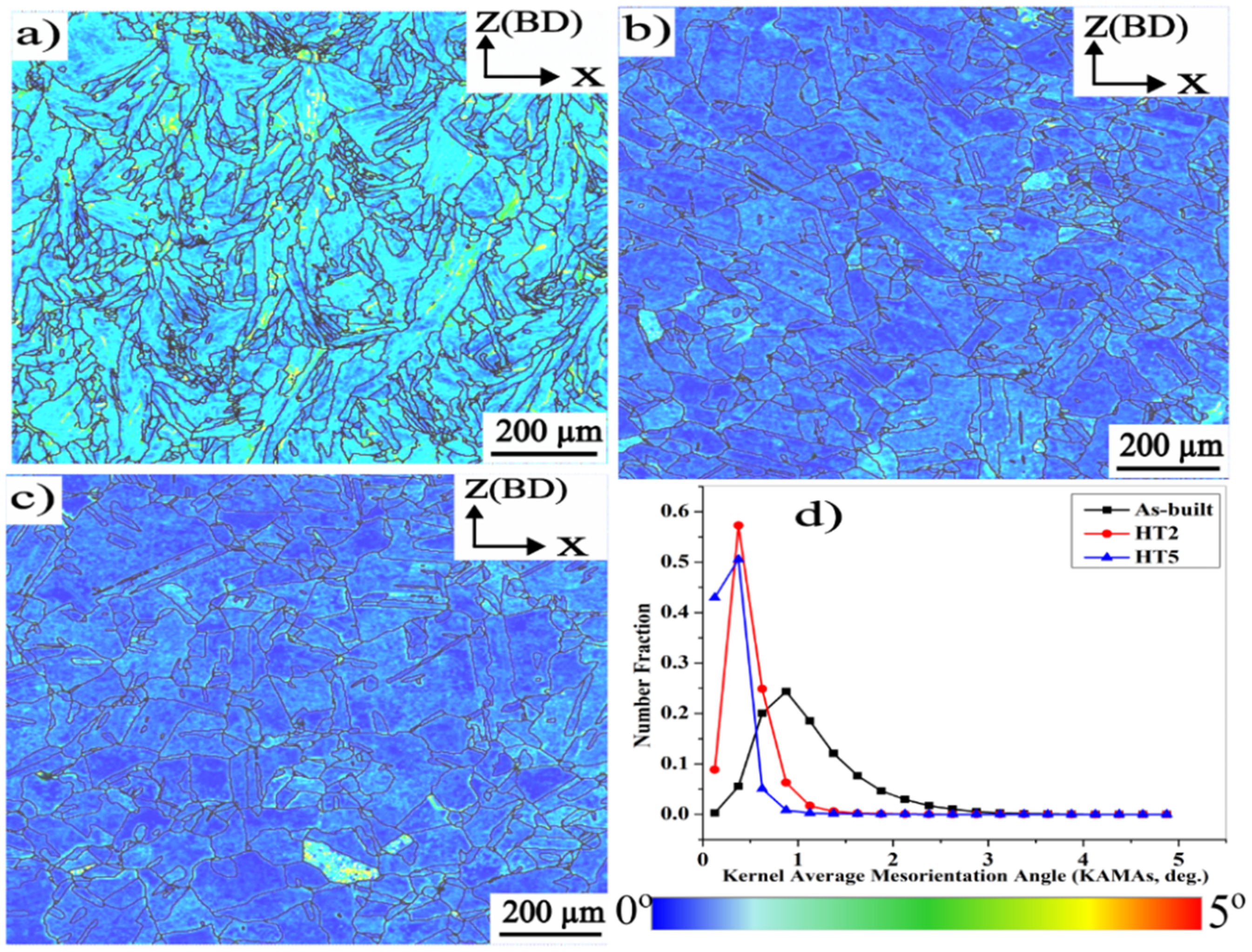
KAMA maps of the
After the HT2 treatment, a slight reduction in the KAMA values to 0.62 degrees is observed as shown in Figure 10(b). This indicates that the 2-h HHT is inadequate to entirely relieve the stored deformation energy, and significant plastic deformation is still present. Under the HT5 heat treatment, a considerable decline in the KAMA value to 0.37° is identified (Figure 10(c)), signifying a greater extent of released stored energy through the dissipation of the dislocation network. Taking into account the isotropic grain structure (Figure 7(e)) alongside the low KAMA values observed under the HT5 conditions, it can be inferred that the HT5 treatment serves as a suitable post-thermal treatment for LPBF IN718 superalloy. This treatment prompts full recrystallization, along with a substantial alleviation of internally generated stresses from fabrication.
Tensile behavior
Figure 11 illustrates the tensile properties of LPBF IN718 superalloy at elevated temperature (650 °C) in both the as-built and heat-treated samples. To provide a comparison, this figure also includes the tensile characteristics of wrought IN718 (AMS5662) at 650 °C, as obtained in. 55
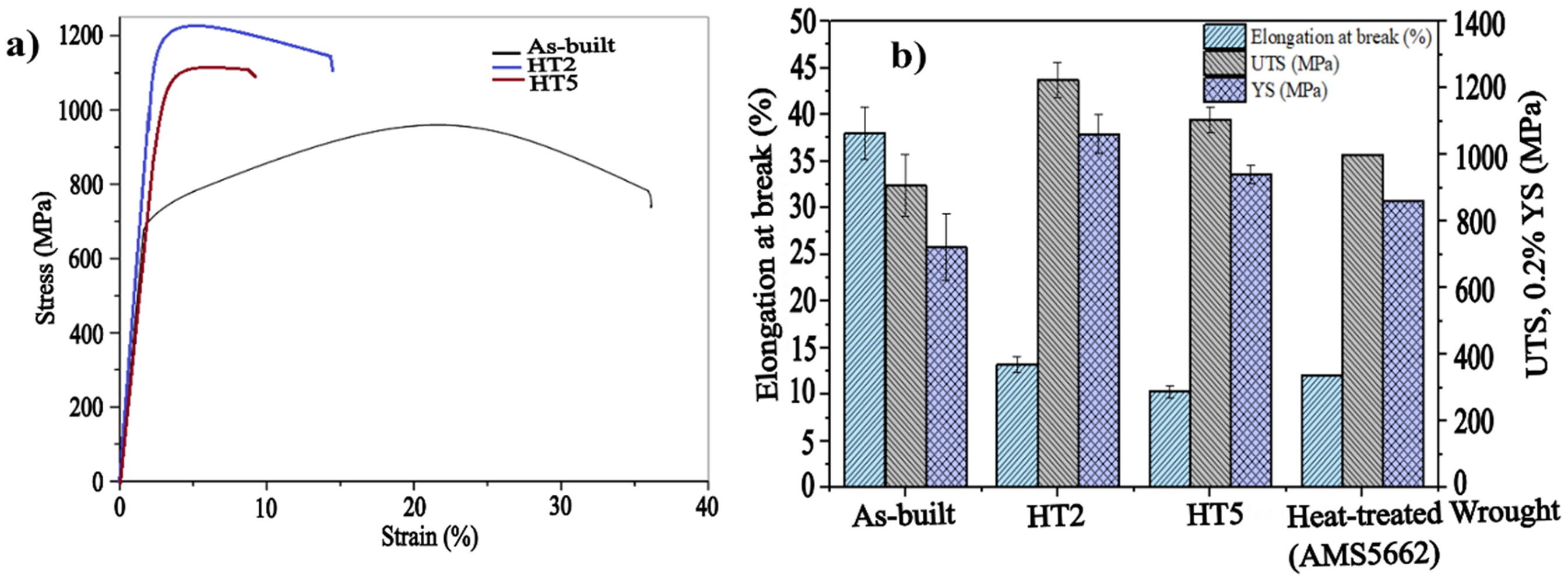
Elevated-temperature (650 °C) tensile characteristics of L-PBF IN718
As depicted in Figure 11, the (UTS) is lower in the as-built condition compared to the thermally-treated conditions, while the elongation at break is the highest. This can be attributed to the dislocation motion and multiplication during tensile strength due to the lack of reinforcing phases (γ׳ and γ״), leading to lower strength and increased ductility. Following both heat treatments (HT2 and HT5), the UTS and YS experienced notable increases, surpassing those of the thermally-treated wrought IN718. However, its elongations at break decreased considerably, becoming slightly inferior to those of wrought IN718. Nevertheless, when compared to the tensile characteristics of the standard thermally-treated LPBF IN718, it becomes apparent that the HT2 and HT5 treatment conditions result in notable enhancements in strength and elongation at break at 650 °C, as depicted in Table 4. Typically, this phenomenon is attributed to the formation of disseminated reinforcement phases (γ’ and γ”) and the presence of intergranular δ-phase, which serve to impede grain boundary and dislocation movement. The kernel average misorientation and sub-grain images indicate that the increased strength of the HT2 condition at elevated temperatures may be attributed to a synergistic impact arising from the inadequate elimination of crystal defects formed during the building process (Figure 10(b)), specifically the sub-grain structure (Figure 9(b), (d)).
In this structure, a significant fraction of low-angle grain boundaries are present alongside the formation of γ׳, γ״, and δ phases. Moreover, the alignment of lengthened grains parallel to the load direction also plays a role in enhancing the ductility of the HT2-treated samples. Nevertheless, following the HT5 treatment, the reinforcement of the material results from a significant presence of annealed twins, demonstrated by a comparatively elevated proportion of CSL Σ3 boundaries and high-angle grain boundaries (Figure 9(d)), alongside the formation of γ׳, γ״, and δ phases. Thus, due to their distinct microscopic structures and fundamental reinforcement mechanisms, the HT2 treatments offer greater strength and ductility compared to the HT5-treated samples. The enhancement of the plastic behavior of materials at high temperatures is elucidated by the temperature-induced activation of atomic and vacancy mobility, which subsequently facilitates plastic deformation through dislocation slip. 55 In contrast to the as-built specimens, the ductility of the HT2 and HT5 conditions specimens decreased when tested at 650 °C. This phenomenon could be attributed to the well-known ductility loss at elevated temperatures observed in nickel-based alloys. 46 It is noteworthy that at 650 °C, the specimens treated under HT5 conditions display a more pronounced decrease in ductility compared to those under HT2 conditions, attributable to a comparatively higher substantial formation of large MC carbides. If an IN718 part is exposed to higher mechanical strength at high temperatures (650 °C), opting for the HT2 condition is a preferred choice, particularly when the application requires homogenized materials with uniform mechanical characteristics.
Fracture surface analysis
Figure 12 shows the fracture surfaces of the transverse cross-section of the as-fabricated (Figure 12(a)–(c)) and heat-treated specimens HT2 (Figure 12(d)–(f)) and HT5 (Figure 12(g)–(i)) of LPBF IN718 samples after the tensile test at 650 °C. The as-built sample of LPBF IN718 shows ductile fracture patterns as illustrated in Figure 12(a).
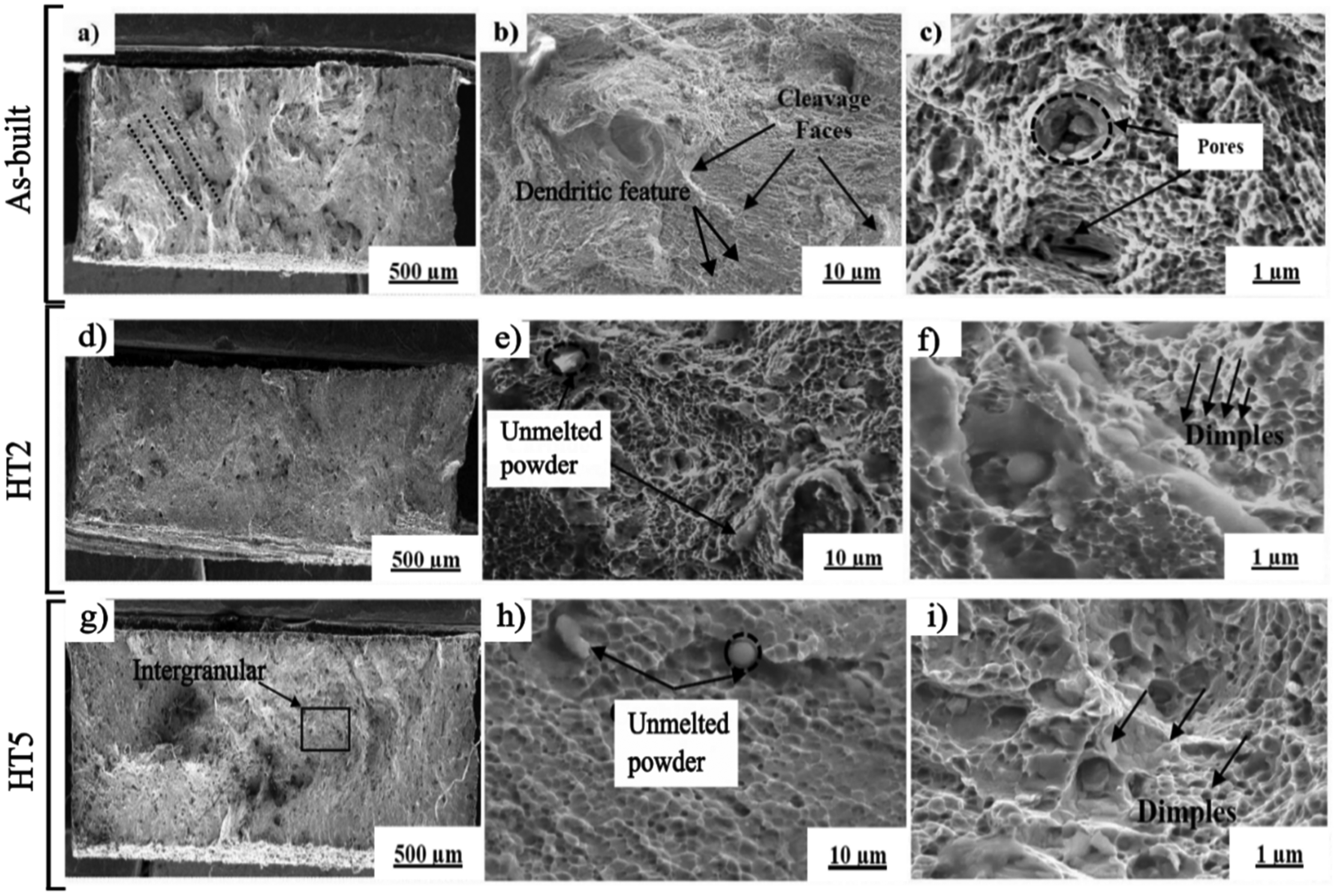
Fracture surfaces of the specimens at 650 °C
Higher magnification SEM micrographs (Figure 12 (b), (c)) of the fracture surface demonstrate dendritic morphology (ductile), cleavage faces, and intragranular and melt pool interface. Additionally, intragranular dimples were observed to align preferentially in a dendritic-like pattern, with orientations varying from one grain to another, as illustrated in Figure 12(b). Additionally, Figure 12(c) demonstrates the existence of coalesced microvoids within the dendrite structure. These microvoids are observed due to the presence of the Laves phase within the dendritic regions. Nonetheless, the dimensions of dimples in the as-built specimen (0.55 ± 0.15 μm) were relatively smaller than those in the HT2 sample (2.27 ± 0.49 μm), indicating the greater ductility observed in the heat-treated samples. Similar concluding statements also have relevant references. 56 In the HT5 treatment, the fractured planes predominantly exhibit a brittle mode, as evidenced by the occurrence of intergranular regions, as depicted in Figure 12(g–(i)). The occurrence of a brittle fracture surface is attributed to the embrittlement phenomenon and the existence of macro-MC carbides following HT5 treatment.
Conclusion
This study aims to optimize the durations of HHT and the temperatures of SHT to achieve superior and isotropic mechanical characteristics in LPBF IN718 parts. The main conclusions can be drawn as follows:
The as-built LPBF IN718 exhibited cellular/columnar dendrites, with laves phases distributed in large amounts of irregular carbides within the grains and at the grain boundary interfaces. Furthermore, a prominent texture along the (100) plane is identified. Subsequent heat treatments play a crucial role in dissolving Laves phases, reducing residual stresses, and forming strengthening γ’ and γ'‘ precipitates in IN718. A HHT exceeding 2 h leads to the diffusion of Ti and Nb, which are critical for the formation of γ’ and γ'‘ phases from the γ-matrix. This hypothesis is supported by a reduction in the γ-matrix lattice parameter following treatments of 4, 6, and 8 h. After a 2-h HHT, significant alterations in the predominant crystallographic (100) texture are noticed. Nevertheless, nearly full recrystallization leading to a noticeably diminished texture in the (100) orientation is achieved after an 8-h HHT. The RSM desirability indicates that the optimum treatment conditions are HT2 (HHT at 1080 °C for 2 h and SHT at 1020 °C for 1 h). The samples treated with HT2 and HT5 at 650 °C demonstrate higher UTS and YS, along with a comparable level of ductility to those of the wrought IN718. The conclusion drawn is that the HT2 treatment provides optimized mechanical properties at 650 °C, along with a preferred crystallographic texture.
Footnotes
Acknowledgments
The authors are gratitude to the Metal Additive Manufacturing Lab at MSME in Bhubaneswar and IIT Kanpur in India for providing access and support during the additive manufacturing experiments and subsequent analysis.
Author contribution(s)
Declaration of conflicting interests
The authors declared no potential conflicts of interest with respect to the research, authorship, and/or publication of this article.
Funding
The authors received no financial support for the research, authorship, and/or publication of this article.