
Abstract
High-temperature oxidation damage of aero-engine turbine blades has attracted increasing attention. However, oxidation and damage behavior of NiCoCrAlY/AlSiY coatings under thermal cycling remain underexplored. Here we systematically investigate thermal residual-stress evolution and crack-damage mechanisms in NiCoCrAlY/AlSiY coatings subjected to different high-temperature cycles, combining experiments with finite-element simulation. Results clarify crack initiation, propagation paths, and damage modes under cyclic loading. By correlating residual-stress distributions with crack behavior, we elucidate the failure process and governing modes (surface/interfacial, Mode I/II). This work establishes an as-deposited baseline and provides theoretical and experimental guidance for the design, processing, and service application of NiCoCrAlY/AlSiY coatings on high-temperature components.
Keywords
Introduction
With the continued advancement of aeroengines, performance requirements for high-temperature alloys are becoming increasingly stringent. Achieving a high thrust-to-weight ratio and lightweight design is paramount; consequently, research on materials that can simultaneously satisfy both criteria is essential. Prior studies have shown that replacing nickel-based superalloys with lightweight, high-strength materials can effectively meet these goals.1–3 TC4 titanium alloy combines low density, high specific strength, and good high-temperature creep resistance, 4 and is therefore widely used in aeroengines. However, TC4 also exhibits shortcomings in high-temperature environments, particularly its relatively weak oxidation resistance.5,6 At present, the simplest and most effective approach to thermally protect hot-section components is to apply high-temperature protective coatings to the surface of superalloys.
Jiang et al. 7 synthesized MCrAlY + AlSiY composite coatings using arc ion plating (AIP). These gradient structure coatings exhibit excellent oxidation and corrosion resistance. Within the temperature range of 700–1050 °C, they effectively protect the superalloy substrate under various working conditions, significantly extending its service life.8–10 Duan et al. 11 deposited NiCoCrAlY/AlSiY on GH907 by AIP and performed a 650 °C/4 h vacuum anneal; across 50 cycles of alternating high-temperature and room-temperature marine exposure, the pure-oxidation condition (E1) showed a mass gain of 3.69 mg·cm−², whereas the hot-corrosion/acid-fog coupled conditions (E2/E3) produced higher mass gains with spallation, attributed to the synergistic catalysis by Cl₂ generated from molten salts and water vapor. Sun et al. 12 constructed a CrAl/NiCoCrAlY/AlSiY gradient coating on a TiAl substrate; under 75% NaCl + 25% Na₂SO₄ at 950 °C for 100 h, the bare alloy and the single-layer NiCoCrAlY spalled and exhibited net mass loss (negative mass change), while the gradient coating showed no obvious spallation and a mass gain of 8 mg·cm−2. Xue et al. 13 densified the AlSiY topcoat using arc-enhanced glow discharge (AEGD); during 1000 h hot-salt corrosion in 75% Na₂SO₄ + 25% NaCl, the AEGD group displayed markedly reduced topcoat porosity and better preservation of the underlying NiCoCrAlY thickness, demonstrating effective suppression of salt ingress and outward elemental diffusion. Bobzin et al. 14 employed AC-HVAF to spray NiCoCrAlY using coarse and fine feedstock; during isothermal oxidation at 1000 °C for 100 h, both coatings exhibited sub-parabolic TGO growth kinetics, with the fine-powder coating showing a lower growth rate and more uniform TGO thickness. Notably, good oxidation stability was retained even without a vacuum heat treatment.
Although numerous studies have investigated oxidation behavior and high-temperature stability, the initiation and propagation of cracks are widely recognized as core mechanisms of high-temperature failure. Numerical simulations by Jiang et al. 15 indicate that residual-stress accumulation accelerates crack initiation and promotes interfacial extension, while Bialas et al., 16 using a cohesive-zone model, validated the accuracy of simulating crack propagation at the TGO/BC interface. However, systematic studies on the crack-damage mechanism of NiCoCrAlY/AlSiY coatings on TC4 titanium alloy remain limited—particularly regarding the coupled relationship between residual stress and cracking under thermal-cycling loads.
Accordingly, this study deposits a NiCoCrAlY/AlSiY composite coating on TC4 titanium alloy, conducts thermal-cycling oxidation at 650 °C, and integrates finite-element simulations to analyze the evolution of thermal residual stress and crack propagation at different cycling stages (40, 80, and 160 cycles). The objective is to establish a baseline failure mechanism in the as-deposited state, thereby providing a theoretical foundation and technical guidance for coating design, optimization of post-deposition diffusion treatments, and the surface-engineering application of hot-section aeroengine components.
Materials and methods
Coating preparation
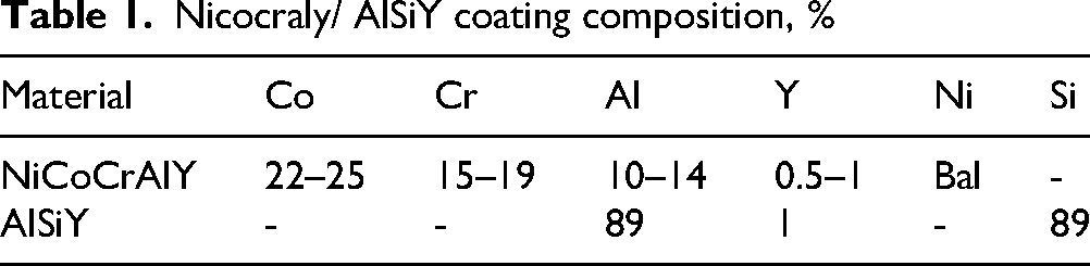
The NiCoCrAlY/AlSiY composite coating was prepared using Ti6Al4 V titanium alloy as the substrate material, with specimen dimensions of 10 mm × 10 mm × 5 mm. Before spraying, the samples underwent a three-step preparation process: sanding with sandpaper to remove oxides, ultrasonic cleaning with alcohol, and drying. The composition of the coating material is detailed in Table 1.
Nicocraly/ AlSiY coating composition, %
High temperature cyclic oxidation experiment
Experiments were carried out in a high temperature muffle furnace. The temperature was set to 650 °C with a heating rate of 10 °C/min. Once the temperature reached 650 °C, it was maintained for 120 min before cooling to room temperature within 30 min. This process constituted one thermal cycle, and the experiment included 160 thermal cycles. Specimens were taken out for surface and cross-sectional morphology characterization after 40, 80, and 160 thermal cycles.
The morphology of the specimens under different conditions was characterized using scanning electron microscopy (SEM, Zeiss ΣIGMA HD), which provided structural parameters for the finite element analysis model. The thickness of the AlSiY and NiCoCrAlY coatings was calculated to be 30 μm and 35 μm, respectively.
Finite-element modeling
Finite element model
According to the cross-sectional SEM image of the specimen, a three-dimensional physical model was established, as shown in Figure 1. The coating system from top to bottom consists of: AlSiY coating, NiCoCrAlY coating, and the TC4 titanium alloy substrate. To simplify the analysis and calculation, the model was reduced to a two-dimensional physical model using only the right half for analysis, as depicted in Figure 2. In Figure 2, X represents the distance from the center of the model to the edge, and Y represents the distance from the bottom of the substrate to the surface of the coating. The X direction is defined as radial, and the Y direction as axial. To facilitate the description of each stress, the stress along the X direction is defined as S11 (radial), the stress along the Y direction as S22 (axial), and the shear stress as S12 The four-node axisymmetric temperature-displacement coupled quadrilateral element (CAX4T) in the finite element software was used for the simulation.
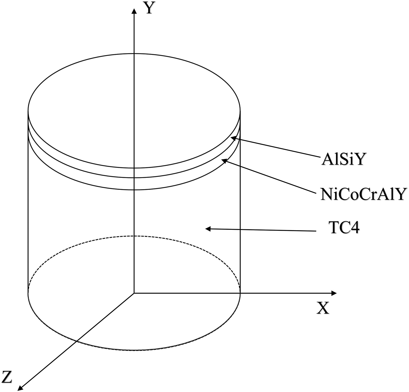
Coating 3D geometry model.
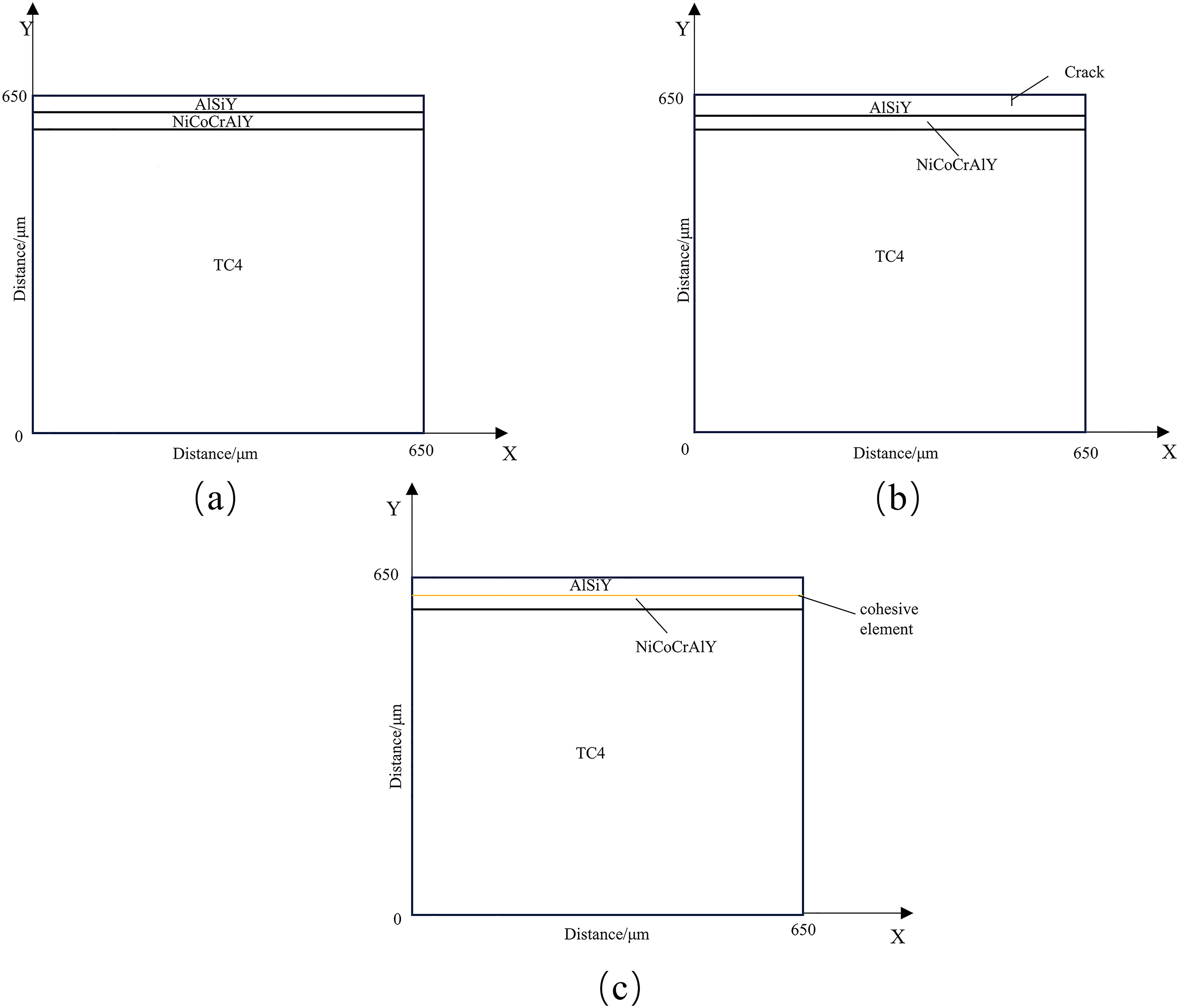
Geometric model of finite element analysis: (a) thermal residual stress (b) surface crack (c) interface crack.
Material parameters and basic assumptions
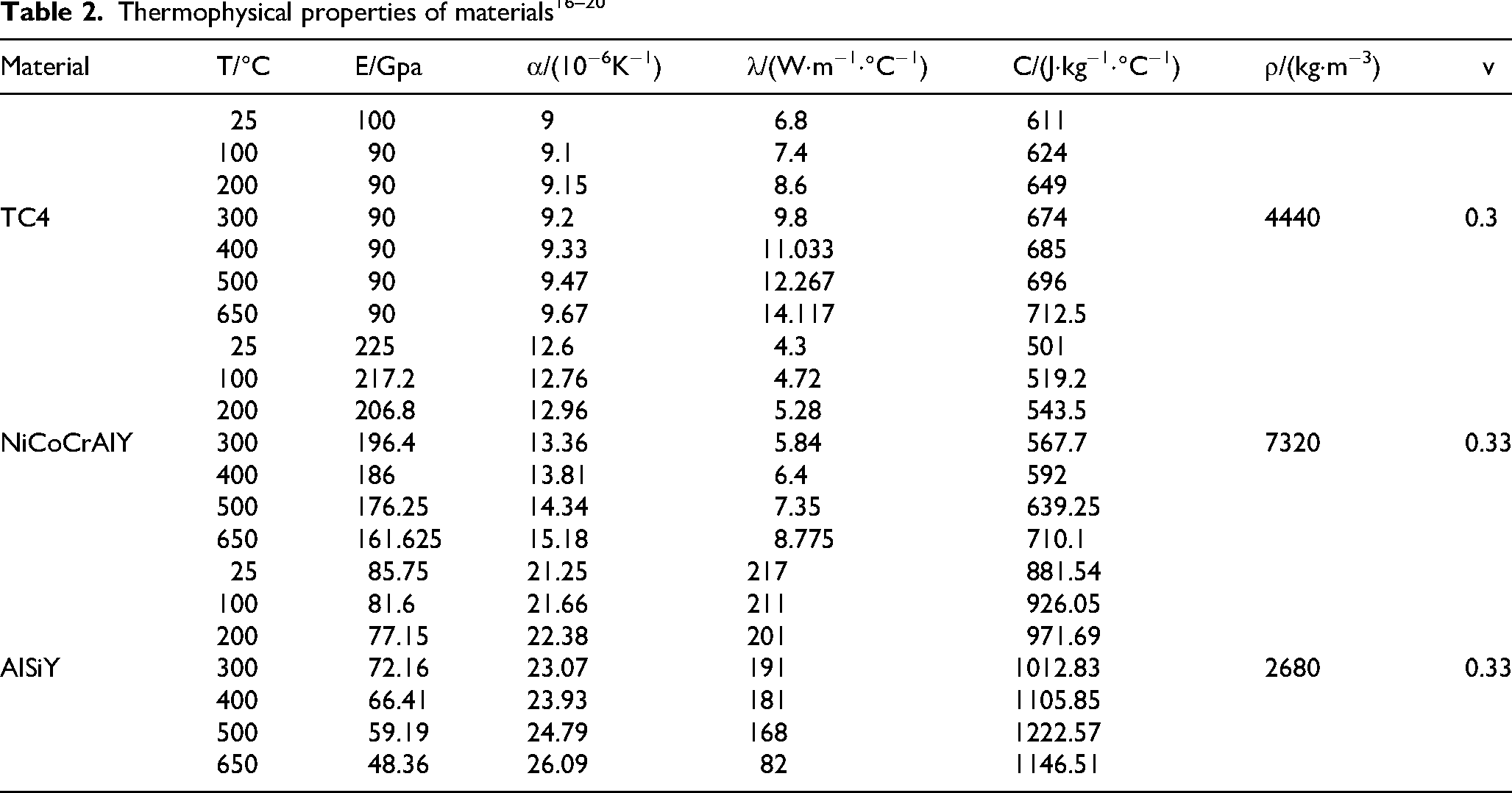
In the finite element simulation, it is necessary to define the thermophysical properties of the materials, including elastic modulus (E), thermal expansion coefficient (α), thermal conductivity (λ), specific heat capacity (C), density (ρ), and Poisson's ratio (ν). The thermophysical parameters of the substrate and coating materials are shown in Table 2, and the material parameters at unknown temperatures are obtained by interpolation and extrapolation. The following assumptions are made in the finite element simulation:
The residual stress of the entire coating system is zero at the initial temperature. There are no micro-defects in the model, such as pores and cracks, and the material properties are isotropic. The coatings are closely bonded to each other, without relative slip, and remain within the range of elastic deformation. The creep and oxidation behavior of materials at high temperatures are not considered.
These assumptions simplify the analysis while ensuring that the essential mechanical and thermal behaviors of the coating system under high-temperature thermal cycling conditions are captured accurately.
Boundary and initial conditions
Initial conditions: The initial temperature of the model at time t = 0 is consistent with the ambient temperature, set to 25 °C and is in a stress-free state.
Force boundary conditions: The degree of freedom of the left side of the model in the X direction is U1 = 0, and the degree of freedom of the lower side in the Y direction is U2 = 0.
Thermal boundary conditions: The upper end surface of the model generates thermal convection with the air. The lower end surface, the left side surface and the right side surface of the model are insulated. The thermal convection coefficient is 65 W / m2·°C.
The (a) mesh is simulated by the four-node axisymmetric temperature displacement coupled quadrilateral element (CAX4T) of the finite element software. (b) A 1μm-long axial crack is preset at the edge of the coating surface and the surrounding mesh is refined to ensure that the surface crack can propagate smoothly under thermal load. The sequential coupling method is used to simulate the surface crack propagation (A temperature field is applied to the model by using the plane four-node axisymmetric temperature-displacement coupled quadrilateral element (CAX4T), the temperature field result file is imported into the crack damage simulation as an input file, and the four-node bilinear axisymmetric quadrilateral element (CAX4R) is used to simulate the surface crack propagation behavior). (c) Four-node bilinear axisymmetric quadrilateral element (CAX4R) with reduced integral and hourglass control is used for meshing, and four-node axisymmetric cohesive element (COHAX4) is used for interface cohesive element. When the strength limit is reached, the cohesive element will be deleted.
Thermal load
In the entire simulation, each cycle is divided into three processes: heating, heat preservation, and cooling. The complete Newton method is used to solve the problem, and a temperature-displacement coupling analysis step is established. The distribution of the thermal stress field in the NiCoCrAlY/AlSiY coating under 40, 80, and 160 thermal cycles is systematically analyzed.
At time t = 0, the model is at a room temperature of 25 °C. The coating structure is then heated from room temperature to a steady-state operating temperature of 650 °C within 65 min. After maintaining this temperature for 120 min, the model is cooled back to room temperature (25 °C) within 30 min. This process is then repeated for the specified number of cycles. The detailed analysis of the step sequence and the thermal cycle process is shown in Figure 3.
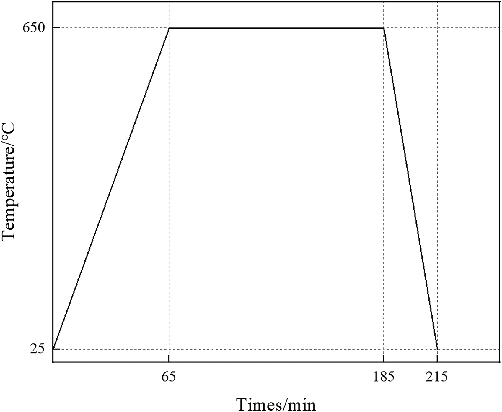
Thermal cycling process.
Result and discussion
Experimental analysis
The SEM morphology of the as-deposited coating is shown in Figure 4(a–b). The coating prepared by arc ion plating exhibits a rough surface with a number of coarse particles and micropores. The cross-sectional view in Figure 4(c–d) shows good interfacial bonding between the NiCoCrAlY and AlSiY layers, although the AlSiY layer exhibits a relatively porous structure. Based on the scale, the thicknesses of the AlSiY and NiCoCrAlY layers were determined to be approximately 30 μm and 35 μm, respectively.

SEM images before and after thermal cycling: (a, b) as-deposited surface morphology at low and high magnification; (c, d) as-deposited cross-sectional morphology at low and high magnification; (e, f, g) surface morphology after 40, 80, and 160 oxidation cycles at 650 °C; (h, i, j) fracture surface morphology after 40, 80, and 160 oxidation cycles at 650 °C.
Figure 4(e–g) shows the surface morphology of the coating after high-temperature cyclic oxidation at 650 °C. Numerous intersecting microcracks were observed on the surface, and their density increased progressively with the number of cycles. This behavior is attributed to the mismatch in thermal expansion coefficients between the thermally grown oxide and the cermet layer, which leads to local stress accumulation and promotes crack initiation and propagation.
Figure 4(h–j) presents the cross-sectional morphology after cyclic oxidation. A large number of axially propagating thermal fatigue cracks were observed within the AlSiY layer. As the number of thermal cycles increased, these cracks gradually penetrated through the NiCoCrAlY bonding layer and reached the TC4 substrate after 160 cycles. This can be attributed to the presence of micropores in the as-deposited coating, which facilitate oxide penetration and growth. The progressive oxidation further accelerates crack extension, ultimately resulting in more extensive coating damage.
Analysis of thermal residual stress results
To facilitate the description of stress, the stress along the X direction is designated as S11 (radial), the stress along the Y direction as S22 (axial), and the shear stress as S12. Tensile stress is considered positive, and compressive stress is considered negative.
Figure 5(a) shows the distribution of radial residual thermal stress in the coating after 40 thermal cycles. Figure 5(b) presents the distribution curve of each stress component along the X direction after 40 cycles. From the Figures, it is evident that the residual thermal stress on the coating's surface is primarily radial stress, manifesting as tensile stress. This tensile stress gradually increases along the radial distance and decreases rapidly at the edge.
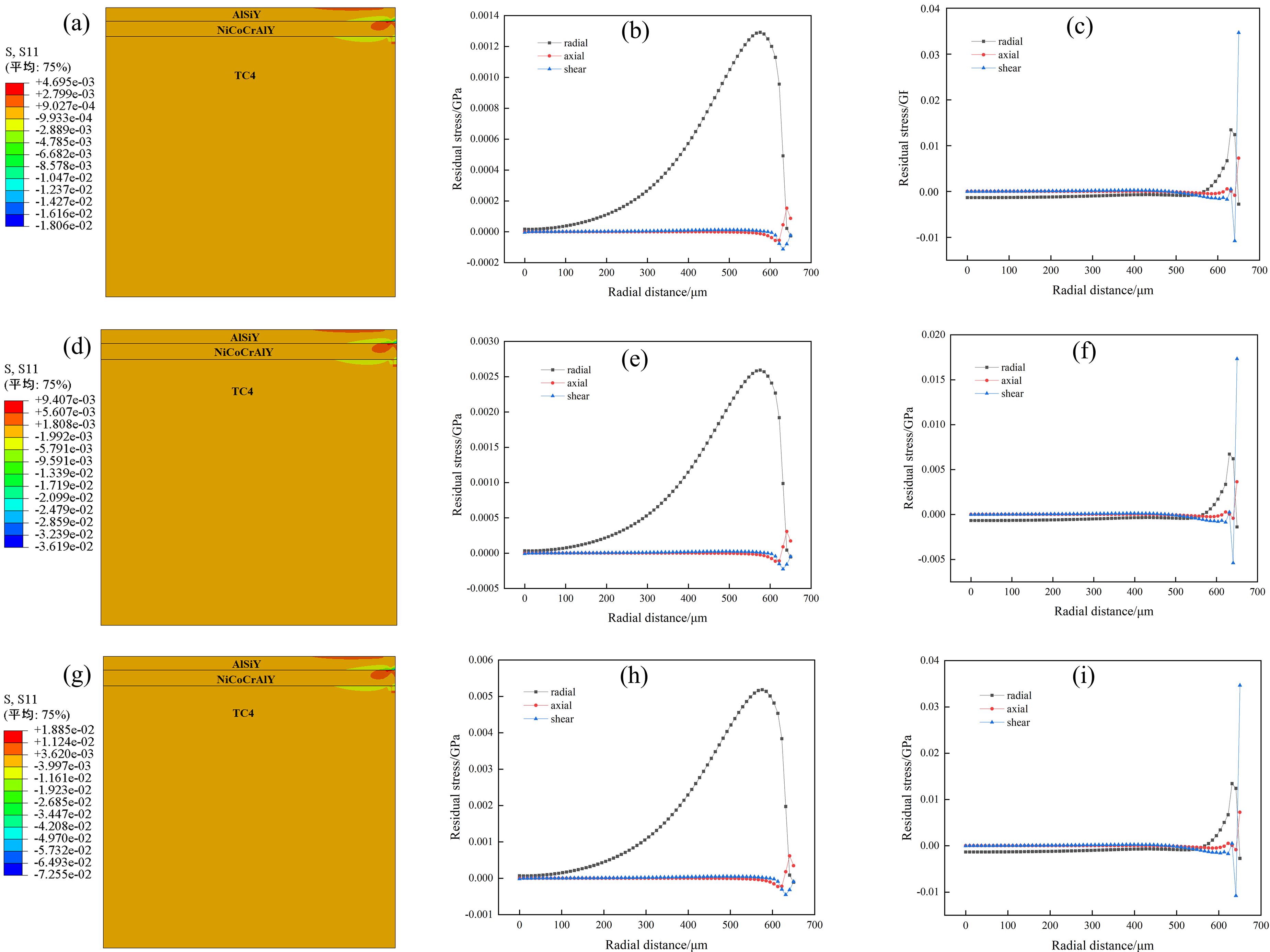
Residual stress contour plots and stress distribution profiles of the coating after different thermal cycles:(a, b, c) 40, (d, e, f) 80, (g, h, i) 160.
The axial residual thermal stress and the shear residual thermal stress are nearly zero. In the radial distance range X = 0 ∼ 572 μm, the radial residual thermal stress increases slowly to a maximum value of 1.29 × 10⁻³ GPa. From X = 572 μm to the edge, the radial residual thermal stress decreases rapidly from 1.29 × 10⁻³ GPa to −0.02 × 10⁻³ GPa. The finite element simulation results indicate that there is significant radial residual thermal stress on the surface of the NiCoCrAlY/AlSiY coating, with a sudden change from tensile to compressive stress at the edge of the coating. The gradient of the radial residual thermal stress is 1.31 × 10⁻³ GPa.
Figure 5(c) shows the distribution curve of each stress component at the interface of the NiCoCrAlY/AlSiY coating after 40 thermal cycles. From the diagram, it is evident that the interface radial residual thermal stress (S11) remains almost unchanged over the radial distance X = 0∼520 μm. However, from X = 520 μm to the radial edge, it rapidly increases from −0.21 × 10⁻³ GPa to 3.35 × 10⁻³ GPa, and then sharply decreases to −0.70 × 10⁻³ GPa.
Additionally, there is a sudden change in shear residual thermal stress (S12) at the edge of the interface, which increases sharply from −2.69 × 10⁻³ GPa to 8.64 × 10⁻³ GPa. The finite element simulation results indicate that there are significant radial residual thermal stress and shear residual thermal stress at the edge of the NiCoCrAlY/AlSiY coating interface, with stress gradients of 4.05 × 10⁻³ GPa and 11.33 × 10⁻³ GPa, respectively.
Figure 5(d) shows the radial residual thermal stress distribution cloud map of the coating surface after 80 thermal cycles. Figure 5(e) presents the distribution curve of each stress component along the X direction after 80 cycles. As depicted, the residual thermal stress on the surface of the NiCoCrAlY/AlSiY coating is primarily radial residual thermal stress. The axial residual thermal stress and shear residual thermal stress only change slightly at the edge position. At the radial distance X = 0∼575 μm, the radial residual thermal stress increases rapidly to a maximum value of 2.59 × 10⁻³ GPa. From X = 575 μm to the edge of the coating, the radial residual thermal stress decreases rapidly from 2.59 × 10⁻³ GPa to −0.054 × 10⁻³ GPa. The finite element simulation results show that after 80 thermal cycles, there is significant radial residual thermal stress on the surface of the NiCoCrAlY/AlSiY coating, with a sudden change from tensile to compressive stress at the edge, resulting in a stress gradient of 2.644 × 10⁻³ GPa.
Figure 5(f) shows the distribution curve of residual thermal stress at the interface of the NiCoCrAlY/AlSiY coating after 80 thermal cycles. The Figure indicates substantial residual thermal stress at the edge of the coating interface. The radial residual thermal stress remains close to zero from X = 0∼520 μm with no significant changes. From X = 520 μm to the edge, the radial residual thermal stress increases to 6.72 × 10⁻³ GPa, then rapidly decreases to −1.39 × 10⁻³ GPa, resulting in a radial residual thermal stress gradient of 8.11 × 10⁻³ GPa.
The axial residual thermal stress remains close to zero with no significant changes. The shear residual thermal stress, however, shows a significant change at the edge, increasing from −5.40 × 10⁻³ GPa to 17.33 × 10⁻³ GPa, with a stress gradient of 22.73 × 10⁻³ GPa. This shear residual thermal stress is much larger than the radial residual thermal stress.
Figure 5(g) presents the radial residual thermal stress distribution cloud map of the coating surface after 160 thermal cycles. Figure 5(h) shows the distribution curve of each stress component along the X direction after 160 cycles. The Figures illustrate that there is significant radial residual thermal stress on the surface of the coating, primarily as tensile stress, which gradually increases along the radial distance and rapidly decreases near the edge. The axial residual thermal stress and the shear residual thermal stress remain close to zero.
Within the radial distance X = 0∼575 μm, the radial residual thermal stress slowly increases to a maximum value of 5.18 × 10⁻³ GPa. Beyond X = 575 μm, it rapidly decreases from 5.18 × 10⁻³ GPa to −0.11 × 10⁻³ GPa. The finite element simulation results reveal a substantial radial residual thermal stress on the surface of the NiCoCrAlY/AlSiY coating, with a sharp transition between tensile and compressive stress at the coating's edge, resulting in a radial residual thermal stress gradient of 5.29 × 10⁻³ GPa.
Figure 5(i) illustrates the distribution curve of each stress component at the interface of the NiCoCrAlY/AlSiY coating after 160 thermal cycles. The radial residual thermal stress at the interface remains almost unchanged within the radial distance X = 0∼520 μm, but rapidly increases from X = 520 μm to the radial edge, rising from −0.87 × 10⁻³ GPa to 13.43 × 10⁻³ GPa before sharply decreasing to −2.72 × 10⁻³ GPa. Additionally, the shear residual thermal stress at the edge of the interface shows a sudden change, increasing dramatically from −10.79 × 10⁻³ GPa to 34.64 × 10⁻³ GPa.The finite element simulation results indicate that there are significant radial residual thermal stress and shear residual thermal stress at the interface edge of the NiCoCrAlY/AlSiY coating, with stress gradients of 16.15 × 10⁻³ GPa and 45.43 × 10⁻³ GPa, respectively.
Figure 6(a) illustrates the radial residual thermal stress distribution curve of the coating surface after 40, 80, and 160 thermal cycles. Figure 6 (b) shows the relationship between the radial residual thermal stress gradient on the coating surface and the number of thermal cycles. The Figures indicate that the radial residual thermal stress on the surface of the AlSiY coating is positively correlated with the number of thermal cycles, meaning it increases as the number of thermal cycles rises.
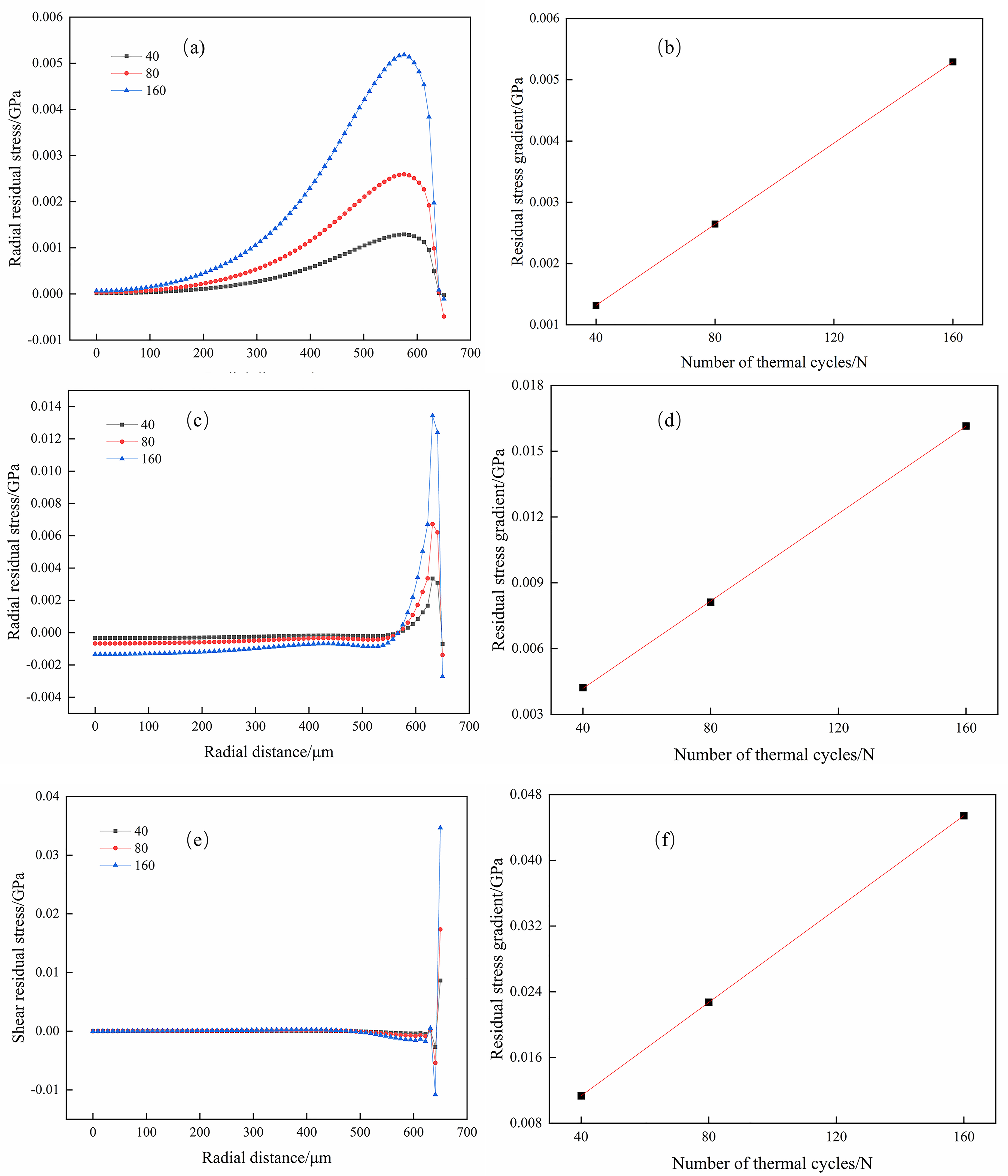
The residual thermal stress stress distribution and stress gradient diagram of the coating in different directions:(a, b) surface radial residual thermal stress, (c, d) interface radial residual thermal stress, (e, f) interface shear residual thermal stress.
A detailed analysis of Figure 11 reveals that with an increase in thermal cycles, the maximum radial residual thermal stress on the surface of the NiCoCrAlY/AlSiY coating escalates from 1.29 × 10⁻³ GPa after 40 thermal cycles to 5.18 × 10⁻³ GPa after 160 thermal cycles. Correspondingly, the radial residual thermal stress gradient increases from 1.31 × 10⁻³ GPa to 5.29 × 10⁻³ GPa. This suggests that as the number of thermal cycles grows, the volume expansion of the AlSiY coating intensifies, leading to an increase in radial residual thermal stress. Consequently, this increase in stress contributes to the initiation and further propagation of axial cracks.
Figure 6 (c) presents the radial residual thermal stress distribution curve of the interface after 40, 80, and 160 thermal cycles. Figure 6(d) shows the relationship between the radial residual thermal stress gradient at the interface and the number of thermal cycles. It can be observed from the Figures that the radial residual thermal stress at the interface of the NiCoCrAlY/AlSiY coating is positively correlated with the number of thermal cycles, meaning it increases as the number of thermal cycles rises.A detailed analysis of Figs. (c, d) reveals that with an increase in thermal cycles, the maximum radial residual thermal stress at the NiCoCrAlY/AlSiY interface escalates from 0.0782 × 10⁻³ GPa after 40 thermal cycles to 13.43 × 10⁻³ GPa after 160 thermal cycles. Correspondingly, the radial residual thermal stress gradient increases from 4.05 × 10⁻³ GPa to 16.15 × 10⁻³ GPa. This increase in stress is significant as it indicates that the thermal cycling process contributes to the buildup of residual thermal stress at the interface, which can have implications for the coating's durability and performance under high-temperature conditions.
Figure 6(e) illustrates the distribution curve of shear residual thermal stress at the coating interface after 40, 80, and 160 thermal cycles. Figure 6(f) shows the relationship between the shear residual thermal stress gradient at the coating interface and the number of thermal cycles. It can be observed from the Figures that the interfacial shear residual thermal stress of the NiCoCrAlY/AlSiY coating is positively correlated with the number of thermal cycles, meaning it increases as the number of thermal cycles rises.A detailed analysis of Figure 6(e, f) shows that as the number of thermal cycles increases, the maximum shear residual thermal stress at the interface of the NiCoCrAlY/AlSiY coating rises from 1.29 × 10⁻³ GPa after 40 thermal cycles to 5.18 × 10⁻³ GPa after 160 thermal cycles. Correspondingly, the shear residual thermal stress gradient increases significantly from 11.33 × 10⁻³ GPa to 45.43 × 10⁻³ GPa. This trend indicates that repeated thermal cycling significantly affects the buildup of shear residual thermal stress at the interface, which could impact the mechanical integrity and lifespan of the coating system under high-temperature operational conditions.
Comparing the radial residual thermal stress and the shear residual thermal stress of the NiCoCrAlY/AlSiY coating interface, it's evident that both values increase with the number of thermal cycles, but the shear residual thermal stress value is notably larger than the radial residual thermal stress. This observation suggests that the shear residual thermal stress is dominant at the interface. Additionally, the radial residual thermal stress and the axial residual thermal stress act synergistically, contributing to the initiation and propagation of radial cracks at the interface.
Analysis of surface and interface crack propagation results
Analysis of surface crack propagation results
The finite element simulation results indicate that the axial propagation of surface cracks primarily occurs during the heating stage. Figure 7 illustrates the crack propagation of the composite coating throughout the thermal cycle. It's evident from the Figure that the crack extends along the axial direction due to thermal mismatch stress. These simulation outcomes align well with experimental observations. With an increase in the number of thermal cycles, the crack steadily enlarges along the axial direction, eventually penetrating through the AlSiY layer into the NiCoCrAlY layer. Subsequently, it continues to propagate along the axial direction within the NiCoCrAlY layer.
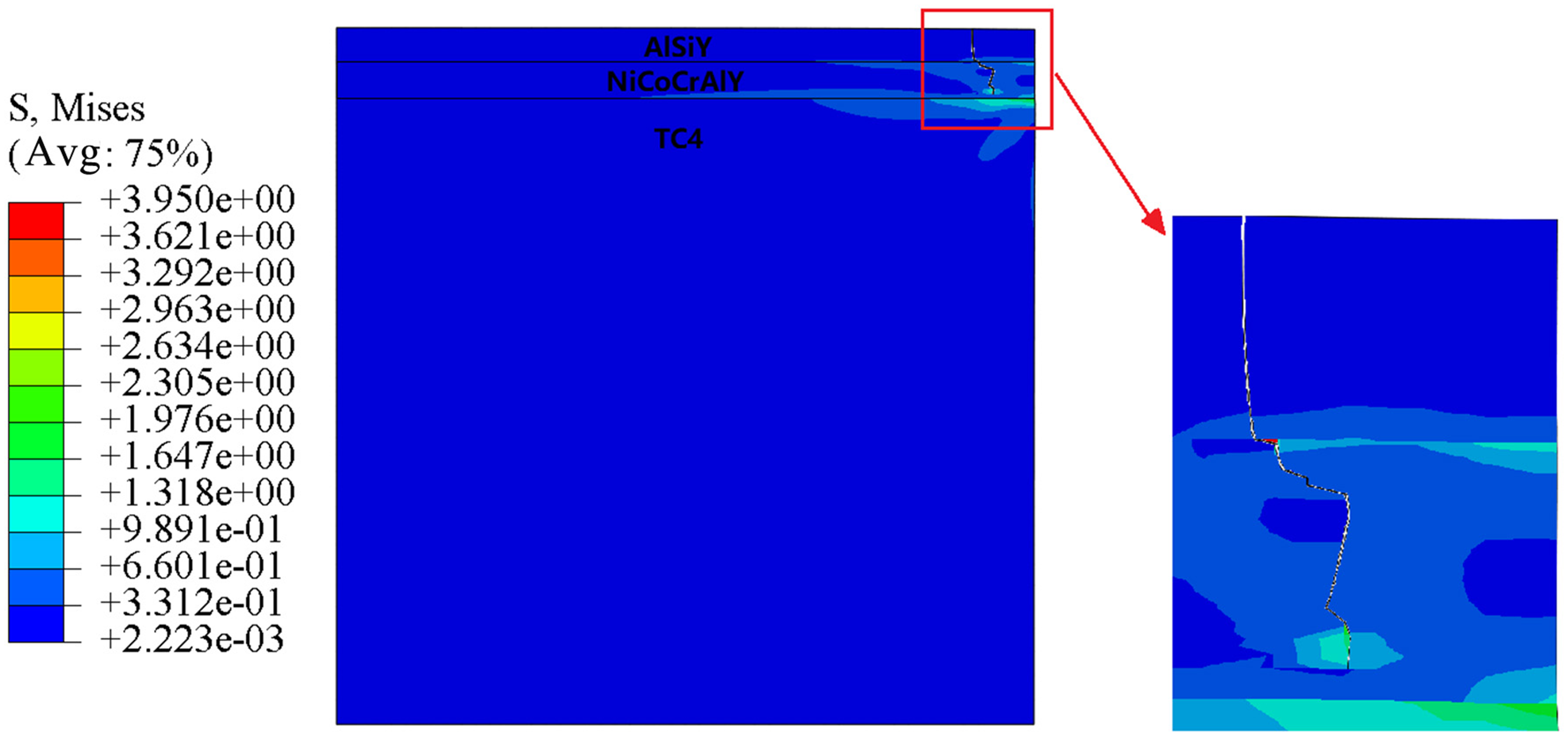
Coating crack extension.
To investigate the primary stress driving crack propagation, the stress value at the crack position of the AlSiY coating during heating was extracted. The stress distribution of the extracted crack is depicted in Figure 8(a). It's apparent from the diagram that the stress along the axial crack propagation direction is predominantly radial stress, mainly exhibiting tensile stress. The axial stress and shear stress exhibit minimal variations. Thus, it can be inferred that the radial tensile stress serves as the principal factor driving crack propagation. This type of crack is categorized as a type I open crack.
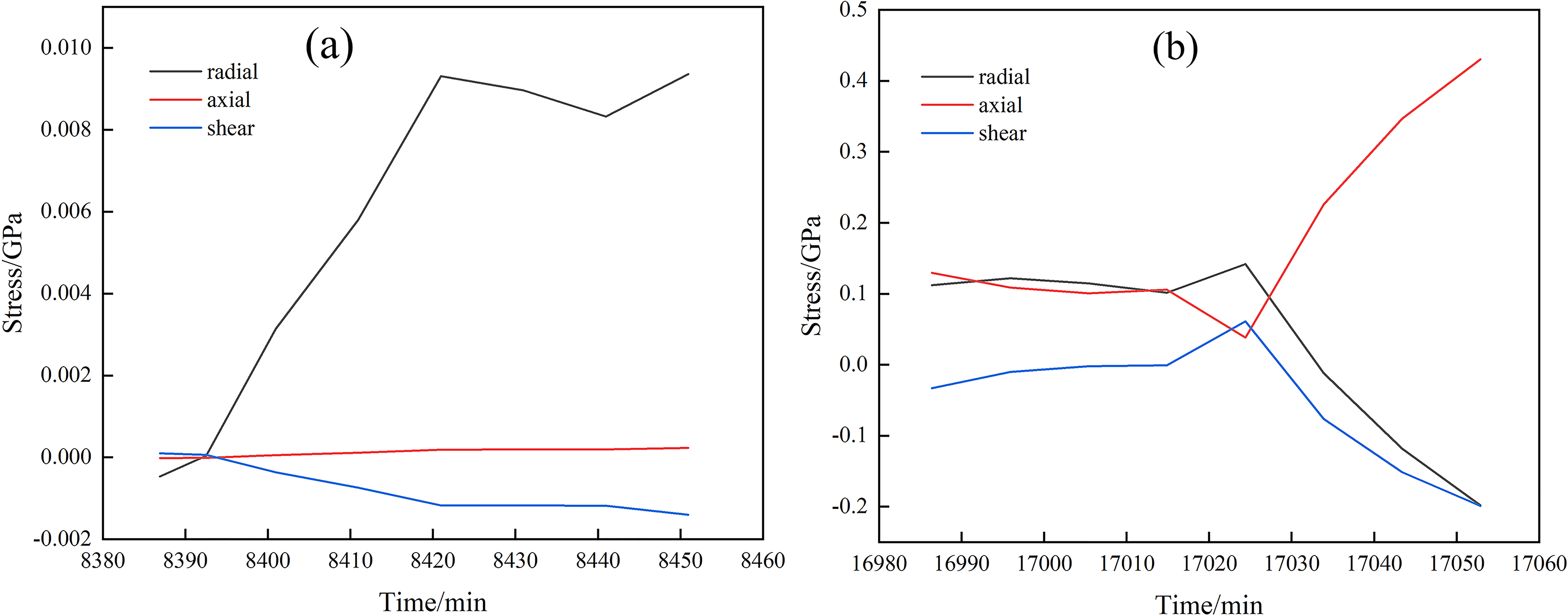
Anisotropic stress curve of coating crack location: (a) AlSiY coating (b) NiCoCrAlY coating.
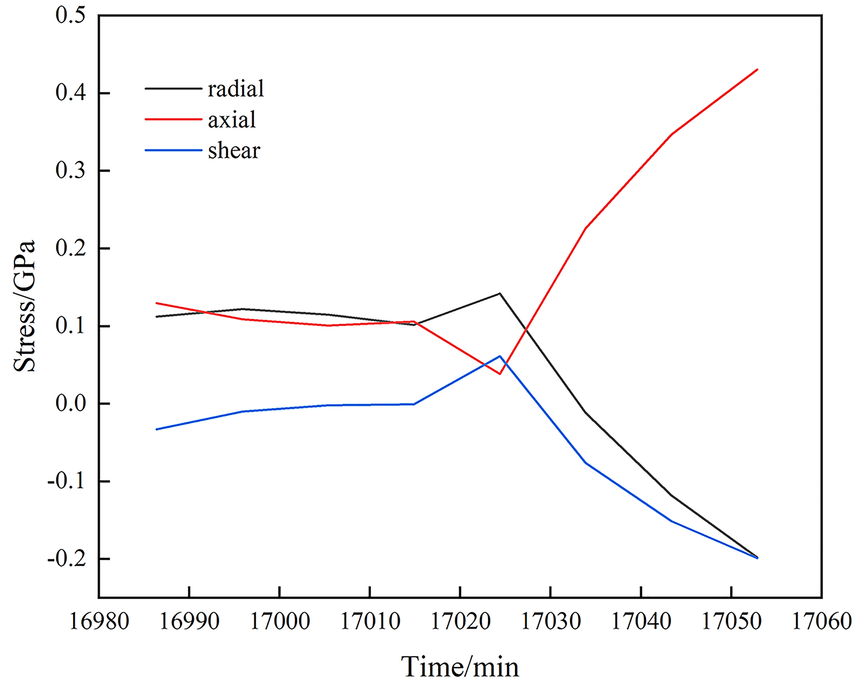
The finite element simulation results indicate that when the crack propagates within the AlSiY layer, its direction of propagation primarily aligns with the axial direction. However, upon reaching the NiCoCrAlY layer, the crack tends to propagate not only axially but also radially. To understand this phenomenon, the stress curve at the crack position of the NiCoCrAlY coating during the heating stage, with respect to the loading time under temperature load, was extracted, as depicted in Figure 8(b).
From the diagram, it's observed that over time, the radial stress (S11), axial stress (S22), and shear stress (S12) exhibit varying patterns. Notably, the axial stress (S22) gradually increases with time, indicative of tensile stress. Conversely, the radial stress (S11) and shear stress (S12) decrease with time. Specifically, the radial stress transitions from tensile stress to compressive stress, while the shear stress displays compressive stress. Consequently, it can be inferred that the crack within the NiCoCrAlY coating is a composite crack, resulting from the combined effects of these three stress components.
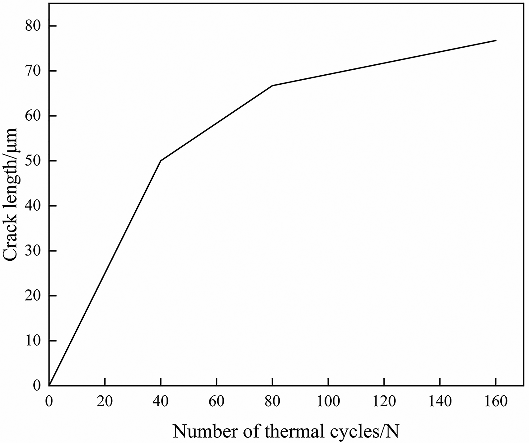
To further elucidate the propagation behavior of the axial crack with an increasing number of thermal cycles, a curve depicting the relationship between the axial crack length and the number of thermal cycles is plotted, as shown in Figure 9. Analysis of the Figure reveals that the axial crack length augments with the escalating number of thermal cycles. Notably, the crack exhibits the fastest propagation during the initial thermal cycle, followed by a gradual deceleration in the propagation speed. This observation suggests that the energy required for the initial crack expansion is relatively minimal, facilitating easy expansion. However, as the crack length increases, the energy necessary for its expansion also escalates. Consequently, multiple thermal cycles accumulate energy, enabling further crack expansion.

Relationship of crack length with the number of thermal cycles.
Figure 10 illustrates the energy release rate at the crack tip under varying crack lengths. It is observed that as the crack length increases, the energy release rate at the crack tip proportionally increases. This trend signifies that longer crack lengths demand greater energy for propagation, thereby resulting in a slower propagation rate. Ultimately, the failure mode of the crack entails continuous expansion of both the surface and interface cracks, culminating in joint failure. The combined effect of these factors precipitates coating spalling failure.
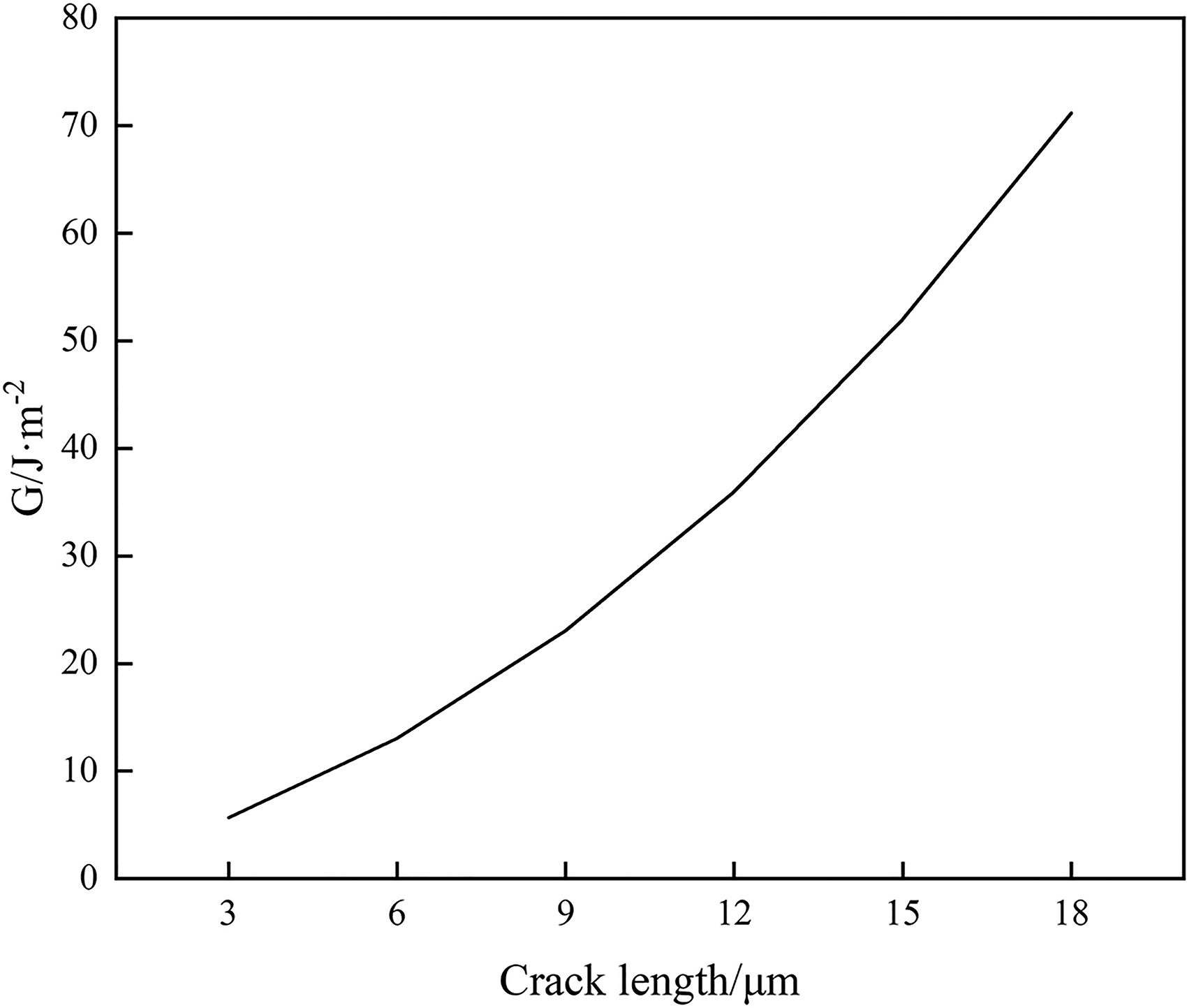
Relationship between energy release rate at crack tip and crack length.
Analysis of interface crack propagation results
When the coating is initially free of stress and defects, the initiation and propagation of interface cracks in the NiCoCrAlY / AlSiY coating under thermal cycling load are depicted in Figure 11. Under the influence of thermal mismatch stress, interface cracks in the coating first appear at the edge position and internally. Subsequently, the cracks at the interface edge expand internally, while internal cracks propagate in both directions. Eventually, the internal and interface edge cracks converge and merge.
Figure 11 illustrates the evolution of crack length with the progression of thermal cycles. It is evident from the Figure that crack propagation is most rapid during the initial 40 thermal cycles, followed by a deceleration in propagation speed. This trend indicates that the energy required for the initial crack initiation and propagation is relatively low. As the crack length increases further, the energy needed for propagation escalates, necessitating multiple thermal cycles to accumulate sufficient energy for further propagation.
Figure 12 displays the stress distribution curve at the interface crack position during the cooling phase. Analysis of Figure 12 reveals that the stress at the interface crack position during cooling primarily consists of radial stress, which is tensile stress. Conversely, axial stress and shear stress tend toward zero. Moreover, the direction of radial stress aligns parallel to the interface crack direction. Hence, it can be inferred that the interface crack predominantly exhibits type II sliding characteristics.
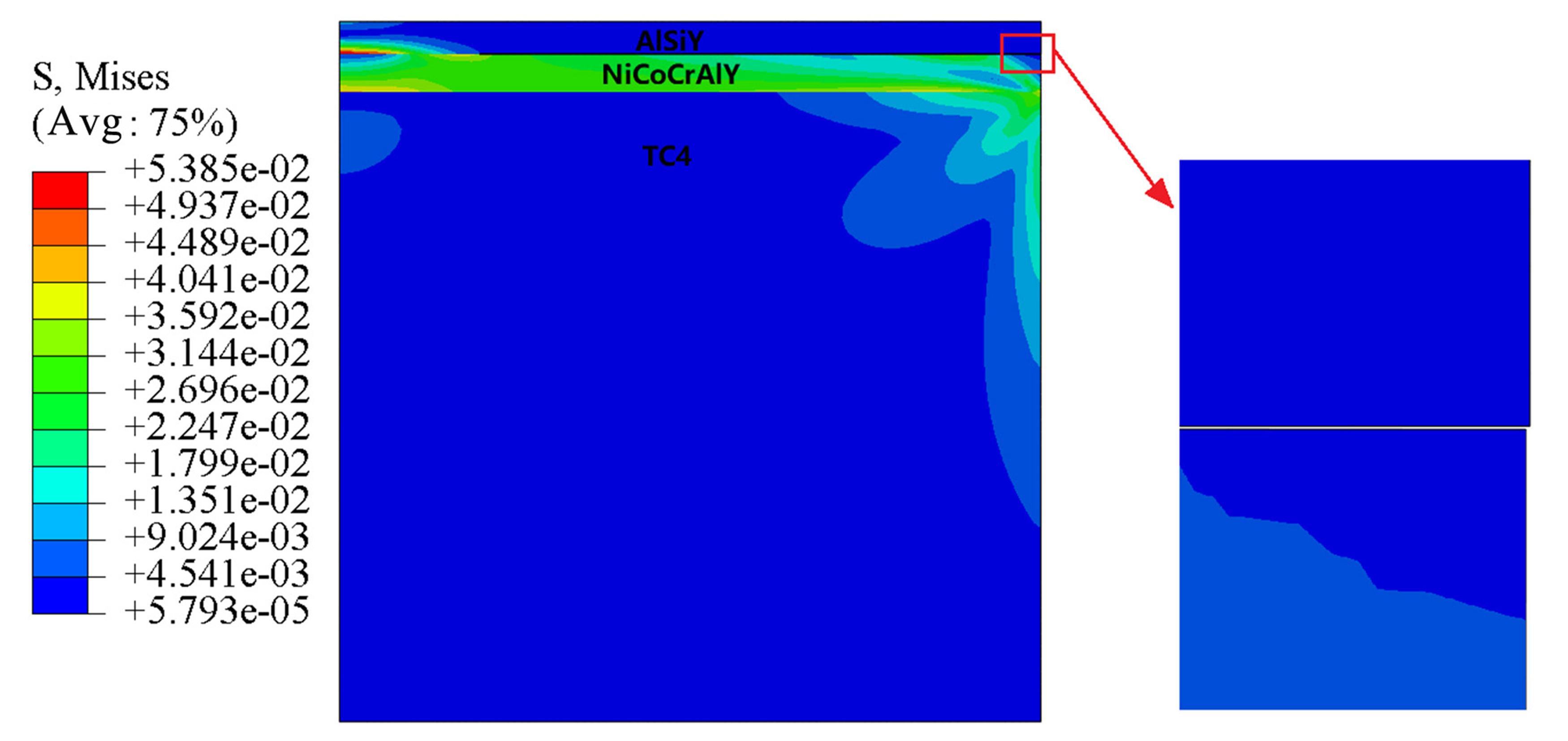
Interface cracking.
Variation of crack length with the number of thermal cycles.
(Figure 13).
Interfacial crack location isotropic stress curve.
Conclusion
This study investigated the thermal residual stress evolution and microcrack initiation and propagation mechanisms of NiCoCrAlY/AlSiY coatings in the as-deposited condition under high-temperature cyclic oxidation through a combination of experimental characterization and finite element simulation. The main findings are summarized as follows:
High-temperature cyclic oxidation induces significant surface and interfacial crack evolution in NiCoCrAlY/AlSiY coatings. Cracks initiate from local stress concentrations caused by thermal expansion mismatch and subsequently propagate toward the substrate with increasing cycles. Radial tensile stress at the coating surface and interfacial shear stress are the primary driving forces for crack initiation and growth. Surface cracks mainly form during the heating stage (mode I), while interfacial cracks predominantly occur during the cooling stage (mode II). The combined action of surface and interfacial cracks leads to coating degradation and eventual spallation. This work provides a mechanistic foundation for optimizing coating design, thickness conFig.uration, and post-treatment processes, contributing to the enhancement of thermal fatigue resistance of TC4-based coatings. Future studies may further refine the predictive modeling of crack initiation and propagation by incorporating diffusion effects and multi-scale damage mechanisms.
Footnotes
Acknowledgments
The work described in this paper is supported by the National Key Research and Development Program (2021YFB3702004).
Author contribution(s)
Funding
The work described in this paper is supported by the National Key Research and Development, (grant number 2021YFB3702004).
Declaration of conflicting interests
The authors declared no potential conflicts of interest with respect to the research, authorship, and/or publication of this article.