
Abstract
In this study, wave absorption-heat conduction composites were prepared by modifying graphene oxide (GO), followed by ultrasonic mixing with carbonyl iron powder (CIP). The composites (0.1 wt% Cu-coated GO) exhibited a minimum reflection loss (RLmin) of −16.47 dB at 2.0 mm and an effective absorption bandwidth (EAB) exceeding 1.44 GHz, while the thermal conductivity reached 2.83 W/(m·K), surpassing that of pure carbonyl iron powder (2.66 W/(m·K)). Increasing the content of Cu-coated GO significantly enhanced the thermal conductivity but the absorption properties exhibited a slight decline. At the thickness of 1–2 mm, the reflection loss peaks for the composites are entirely within the S-band. Therefore, the CIP/Cu-coated GO composites demonstrate strong potential for S-band applications.
Introduction
With the increase of communication devices and electronic equipment, the electromagnetic radiation (EMR) poses a potential threat to human health and surrounding electronic systems.1–4 The electromagnetic wave (EMW) absorbing materials are capable of converting electromagnetic energy into heat or other forms, which can be considered a reliable method to resolve the hazards of EMR.5,6
Excessive heat accumulation induces device overheating, which leads to the reduction of operational efficiency and long-term reliability of electronic devices.7–9 Moreover, the high integration and miniaturization of electronic equipment further increase the demand for heat dissipation.10,11 The thermal conductivity of materials has become a significant factor in the development of absorbing material.12,13 Therefore, wave absorption-heat conduction composites with dual functionality are urgently needed in application fields such as microelectronic packaging and fifth-generation (5G) wireless systems.14,15
The thermal conductivity of absorbing materials has been shown to be significantly enhanced by adjusting the type of materials, size, shape, and mass ratio of thermally conductive fillers, with interesting results. 16 For instance, the ZnO/exfoliated graphite (EG)/epoxy composites have been prepared with integrated thermal conduction and EMW absorption, as reported by Singh et al.. 17 Li et al. 18 also reported that the MXene/Co/PVDF composites with integrated thermal conduction by incorporating MXene and Co into the PVDF matrix. Pan et al. reported that the PMMA/Ni@GNP nanocomposites show a good EMW absorbing property. Notably, the composite with 30 wt% Ni@GNP displays the best EMW absorption performance and good thermal conductivities. 19
Carbonyl iron powder (CIP) was widely used as materials for wave absorption due to moderate electrical conductivity and high saturation magnetization strength.16,20 However, they suffer from the inherent drawback of relatively low thermal conductivity, excessive density, poor impedance matching.16,21 Carbon-based materials such as graphite, 22 graphene, 23 and carbon nanotubes (CNTs) 24 display a great potential as a thermal conductive filler due to their large thermal conductivity.
Although GO does not possess the high thermal conductivity of above carbon-based materials, its unique properties make it a highly promising thermal conductive filler.25,26 GO is usually synthesized via the Hummers’ method, which involves exfoliating graphite in a concentrated acid and oxidizing environment. 27 In this way, the GO contains more oxygen-containing functional groups that lead to its excellent dispersibility, hydrophilicity and facile modification to produce other graphene-based materials. 28 Its excellent dispersibility ensures uniform distribution on the matrix and promotes the formation of an efficient thermal network. The ease of surface modification allows GO to be combined with other high thermal conductivity materials. Furthermore, its extremely high specific surface area enables it to bond tightly with high thermal conductivity materials, thereby enhancing the thermal conductivity of the composite. Additionally, GO offers low density and mechanical strength, which makes it particularly well-suited for advanced applications pursuing lightweight design and multifunctional integration. 25 Therefore, GO has been extensively used. For example, Liu et al. 29 reported that the SnS/GO hybrid was fabricated via a solvothermal method, which demonstrated excellent electromagnetic wave absorption capabilities. Similarly, Jiang et al. 30 fabricated low-density graphene@SiC aerogels through directional freeze-casting and thermal reduction of GO-coated SiC whiskers, enhancing microwave absorption. Xiao et al. 31 prepared Fe3O4/graphene nanocomposites via solvothermal method by embedding Fe3O4 nanospheres into GO sheets to balance dielectric and magnetic properties.
GO also has some limitations. GO exhibits thermal instability and can readily undergo self-propagating disproportionation reactions to yield chemically modified graphene or reduced graphene oxide (r-GO) under mild heating conditions. 32 Moreover, the presence of oxygen-containing functional groups on the surface of GO significantly diminishes π–π stacking interactions, which will reduce conductivity and introduces lattice defects within GO. 33
Electroless plating, a chemical deposition technology, enhances the oxidation resistance, corrosion resistance, conductivity, and wear resistance of the substrate material by depositing metals from solutions without external voltage.34,35 Copper, with the second lowest resistivity in nature and a high free electron density, has attracted the attention of researchers due to its low cost, solderability, electro-migration resistance, and high electrical and thermal conductivity. 36 Electroless copper plating with its excellent conductivity, corrosion resistance and shielding capabilities is also widely used in absorbing materials. Li et al. 37 reported that ultrasonic electroless copper plating of CIP in non-woven FCAM effectively enhanced microwave absorption properties. Xie et al. 38 reported that the Cu-coated carbonyl iron/Co composite powders were prepared by ball milling and electroless plating, which enhanced absorbing stability and corrosion resistance. Li et al. 39 reported that the Fe/Cu composite samples, prepared by chemical plating of Cu particles on carbonyl iron sheets with the excellent microwave absorbing at an optimal plating time of 30 min.
To overcome the inherent limitations of GO, it is usually modified before practical application. 40 For instance, Yang et al. 41 reported that the acidulated GO was synthesized through esterification followed by substitution of surface hydroxyl groups on graphene oxide. Bhunia et al. 42 used hydrazine as a reducing agent to selectively remove hydroxyl groups and epoxy bonds from graphene oxide while retaining carboxyl anions. Bonanni et al. 43 eliminated oxygen-containing groups from GO via a reduction process and consequently reintroduced carboxyl groups onto the graphene surface.
To date, experimental studies on the modification of GO via electroless copper remain limited. In this work, the Cu-coated GO/CIP composite as a dual-functionalized composite for wave absorption and thermal conductivity was successfully designed and prepared by electroless copper plating process and ultrasonic mixing. This work aims to investigate the relationship between the wave absorption/thermal conductivity properties and the GO filler. The effect of doping content of GO filler on the microstructure, wave-absorbing, and thermal conductive properties was also studied.
GO was modified by chemical copper plating as the thermal filler. The chemical copper plating can modulate dielectric, thermal conductivity property of GO. The filler can reduce contact between CIP particles, leading to increased interface losses and polarization losses. Moreover, at low filler levels (≤1 wt%), slightly impact on wave absorption properties, maximized the thermal conductivity of the absorbing composites. In summary, the cost-effective and easy preparation method for wave absorption-heat conduction materials was provided in this work, which is also suitable for engineering applications.
The whole manuscript is divided into four sections. The background, motivation, and the novelty of the work were described in the introduction (section 1). The experiment steps, technique parameters, measurement methods were described in experiment (section 2). The results and discussions (section 3) are composed of the experimental results and related discussions, covering the morphological characteristics, absorption properties, and thermal conductivity of the composites. Finally, the conclusions (section 4) summarize the experimental results and potential applications.
Experiment
Materials
The graphene oxide (GO) powders were purchased from Jiangsu XFNANO Materials Tech Co., Ltd (Nanjing, China). EDTA-2Na, sodium hydrate (NaOH), hydrochloric acid (HCl), Formaldehyde (HCHO), Tin chloride (SnCl2), Palladium chloride (PdCl2) and Copper sulfate pentahydrate (CuSO4·5H2O) were purchased from Sinopharm Chemical Reagent Co., Ltd The Anhydrous ethanol was purchased from Wuxi City Yasheng Chemical Co., Ltd The carbonyl iron powder (CIP) was purchased from Jiangsu Tianyi Ultra-fine Metal Powder Co., Ltd
Preparation of electroless copper plating Go
The GO powders (0.5 g) were put in deionized water (1 L), after that the ultrasonic dispersion was operated for 5 min. The dispersed GO powders were filtrated and dried at 50°C for 2 h. The sensitizing solution consisting of 40 mL/L HCl and 20 g/L SnCl2 was used. The GO and the sensitizing solution at a ratio of 0.5 g:1 L were placed into a beaker for GO sensitization. With magnetic stirring, the beaker was immersed in a water bath maintained at 85°C for 60 min. After that, the sensitized GO was washed with deionized water, and dried at 50°C for 2 h.
The activating solution was prepared by 40 ml/L HCl and 0.5 g/L PdCl2. The sensitized GO and the activating solution at a ratio of 0.5 g:1 L were placed into a beaker. The temperature, magnetic stirring, and the process time for activation are similar to those of sensitization. After that, the activated GO was washed with deionized water, and dried at 50°C for 2 h.
The copper plating solution was prepared with the following components: 10 g/L CuSO4·5H2O, 15 g/L EDTA-2Na and 15 g/L NaKC4H4O6. The activated GO and the copper plating solution at a ratio of 0.5 g:1 L were placed into a beaker. Under the temperature of 80°C, the electroless plate was started by maintaining the pH range of 12.0 to 12.5, which is tuned by titrating NaOH solution. Moreover, the 10 mL/L HCHO was titrated during plating process. The reaction was continued for 10 min. After that, the plated products were washed three times with anhydrous ethanol and dried at 50°C for 2 h. Then, the Cu-coated GO was obtained.
Synthesis of thermal conductive wave-absorbing composites
The CIP was thoroughly blended with the Cu-coated GO by the ultrasonic mixing in anhydrous ethanol (120 W, 10 min). After that, the mixture was dried under vacuum at 50°C for 8 h. The thermal conductive wave-absorbing composite was obtained. By repeating the above steps, the series of composite materials (0.1 wt%, 0.3 wt%, 0.5 wt%, 0.8 wt%, and 1.0 wt%) were fabricated.
Characterizations
The crystal structures of the samples were detected by X-ray diffraction (XRD). The morphology was characterized by scanning electron microscopy (SEM, Zeiss EVO-18). The complex permittivity and complex permeability were measured by using Vector Network Analyzer (VNA) in the range of 1–18 GHz. The thermal conductivity of the absorbing materials was measured by using Quick Thermal Conductivity Meter. Thermal conductivity measurements were conducted on the disk of composite (5 wt% paraffin, 30 mm diameter × 2 mm thickness), which is molded under the pressure of 20 MPa. The composite powders for electromagnetic measurements were wax composites at a mass ratio of 85 wt%,and then the powder/paraffin composites were die-pressed to form cylindrical toroidal specimens with 7.0 mm outer diameter, 3.04 mm inner diameter and 3 mm thickness. Based on the transmission line theory, the reflection loss (RL) can be calculated by the following equation.
44

Here,
Results and discussion
The XRD pattern of the composites is shown in Fig. 1. The XRD pattern of Cu-coated GO sample exhibits three different distinct diffraction peaks compared to that of GO. The first diffraction peak appears approximately at 25.08°, which is significantly different from the characteristic (001) peak of GO at 10.9°. The notable variation in diffraction angles can be attributed to the electroless copper plating process, which impacts the interlayer spacing (
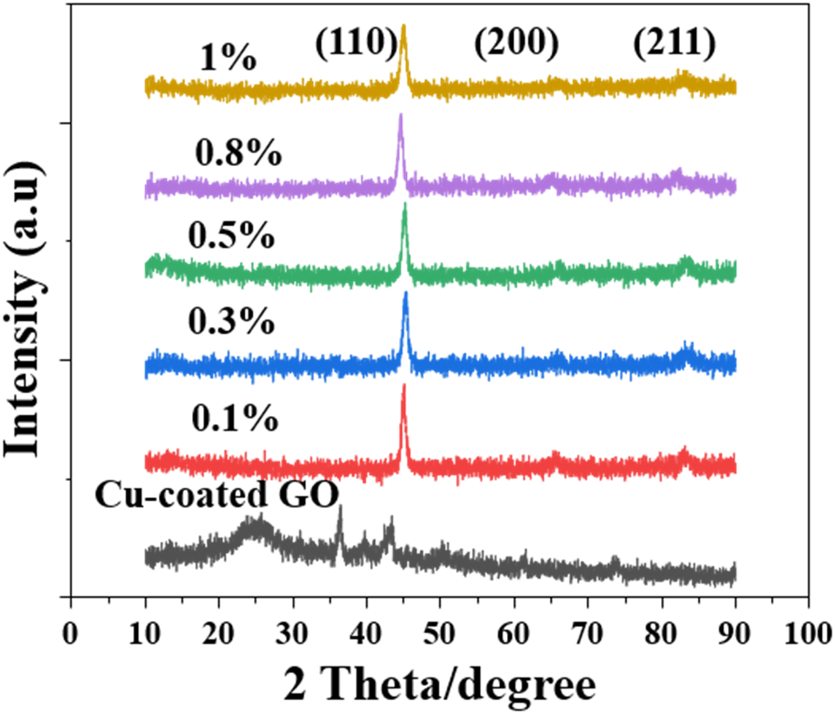
The XRD pattern of the composites and filler.
The SEM images of the Cu-coated GO and CIP/Cu-coated GO composites are shown in Fig. 2. As illustrated in Fig. 2(a), the Cu-coated GO samples exhibit a relatively small particle size ranging from 30 to 40 µm. The particles of Cu-coated GO displayed the sheet-like structure, which is similar to that of GO.52,53 It is well known that a flake-like absorbing material exhibiting shape anisotropy can exceed the Snoek limit. 54 It is indicated that the chemical plating process primarily affects GO by modifying its functional groups and interlayer interactions, rather than altering its microstructural characteristics. 55 Meanwhile, the surface roughness of GO particles increases after chemical copper plating. Figure 2(b)–(f) show the CIP/Cu-coated GO composites with varying mass fraction of Cu-coated GO. The particle size of composites is approximately 10–20 µm, as measured by the Nano Measurer. It can be seen that after ultrasonic mixing, the shape of the composites is significantly different from that of pure CIP. 56 The composites also exhibit a flake structure, demonstrating a localized agglomeration phenomenon.
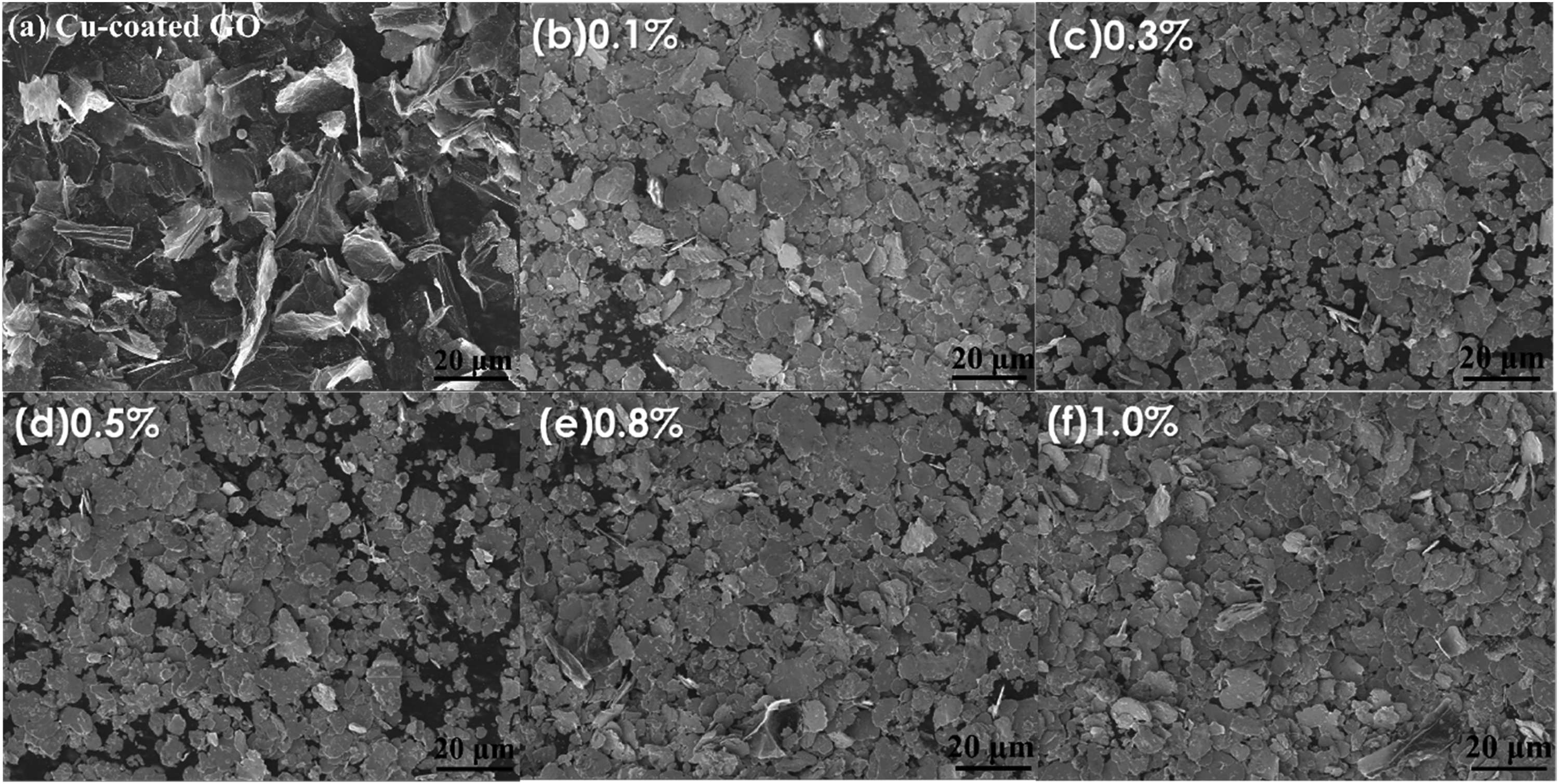
SEM images of the composites: (a) Cu-coated GO and (b)-(f) CIP/Cu-coated GO composites.
The Raman spectra of all samples, CIP and Cu-coated GO are shown in Fig. 3. The Cu-coated GO composites only display one strong signal centered at 1303 cm−1, which corresponds to the D band (the vibration of sp3 defects and the disorder sites) of carbon. 51 Compared to carbon, the composites after the chemical copper plating process exhibit the absence of the G band (the ordered state of sp2-hybridized carbon lattice). 57 The phenomenon may be attributed to the reducing agents in the chemical plating solution, which leads to the decrease of sp2 domain size after the reduction process. 58 The Raman spectra of the composites in this work exhibit characteristics that differ from those reported in previous studies. For instance, Liu et al. 29 reported that SnS/GO hybrids show both D and G bands with an ID/IG ratio of about 1.06, and this change suggests the presence of increased defects and relevant lattice deformation on GO plates. Similarly, Jiang et al. 30 reported that the clear D and G bands were shown in GO@SiC aerogels, with an ID/IG ratio of 1.15, which is close to that of pristine GO. Moreover, the CIP with different doping contents has also one characteristic Raman peak near 1303 cm−1, which also corresponds to the D band of carbon. The D band of CIP with different doping contents may originate from carbonyl groups in CIP. 59
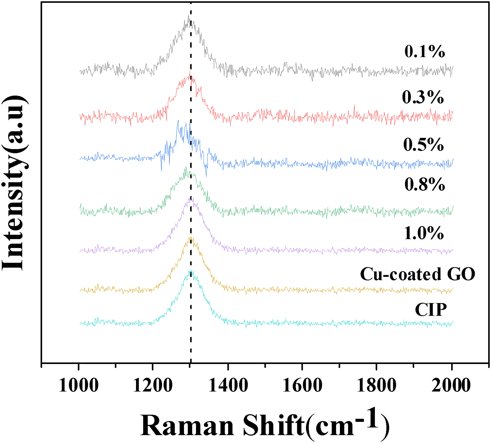
Raman spectra of the CIP/Cu-coated GO composites, Cu-coated GO and CIP.
The complex permittivity and complex permeability of all samples within the frequency range of 1–18 GHz are shown in Fig. 4. The complex permittivity is expressed as
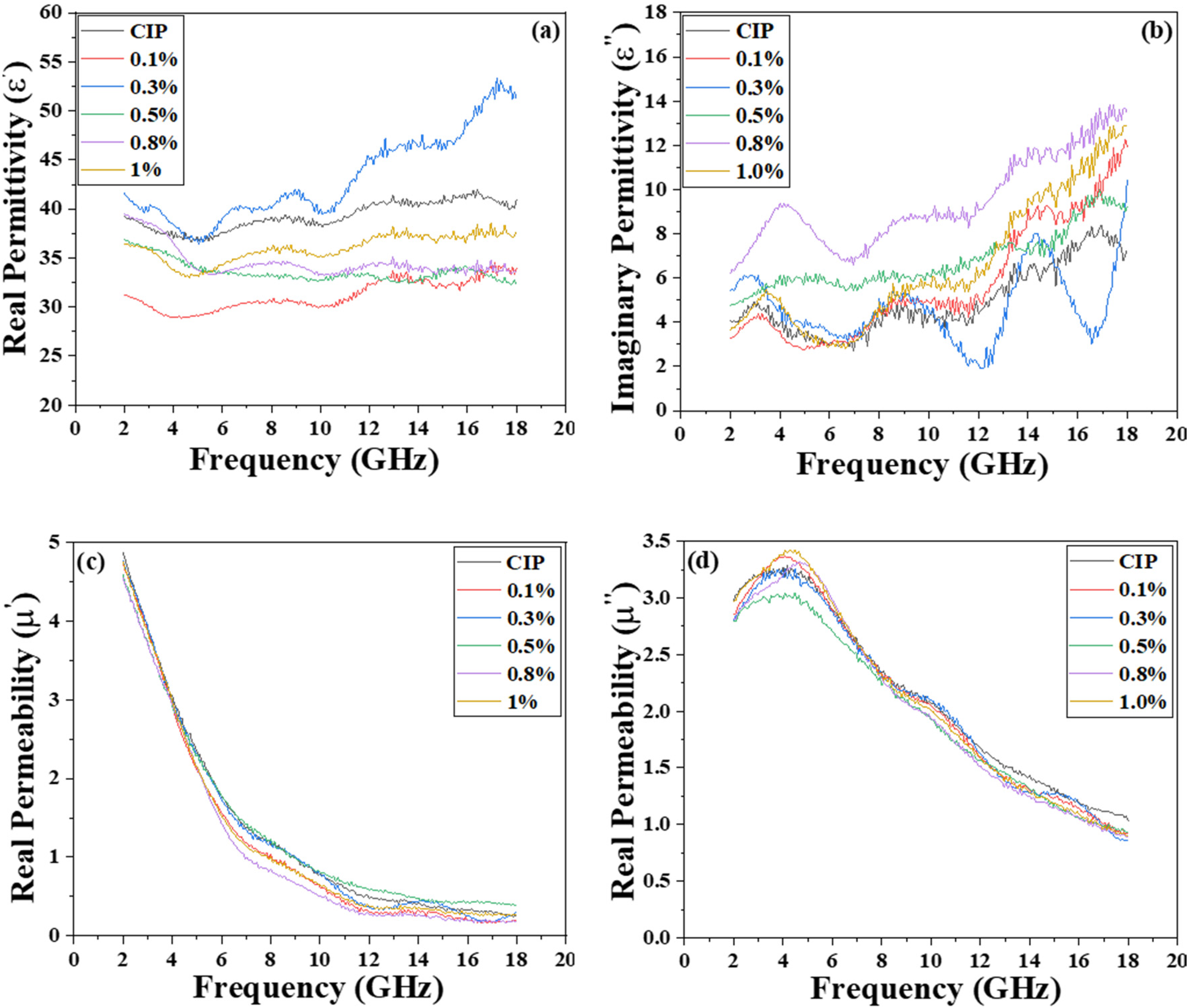
Complex permittivity of the CIP and CIP/Cu-coated GO composites: (a) real
The real permittivity (
The imaginary permittivity (
Figure 4(c) shows the frequency dependence of
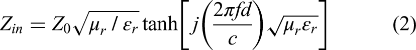
The parameter
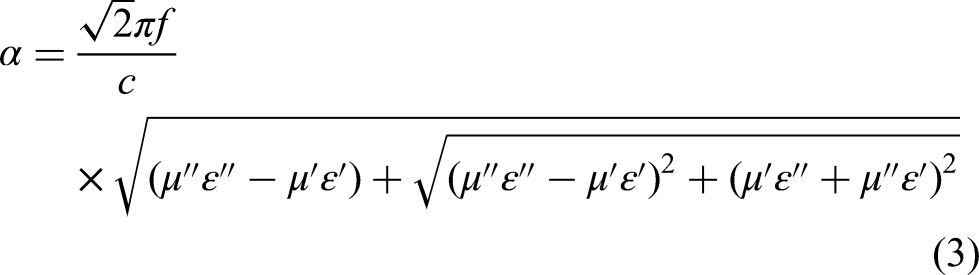
Here, f represents the frequency, while c represents the speed of light in free space.
The increased values of
The attenuation constant (
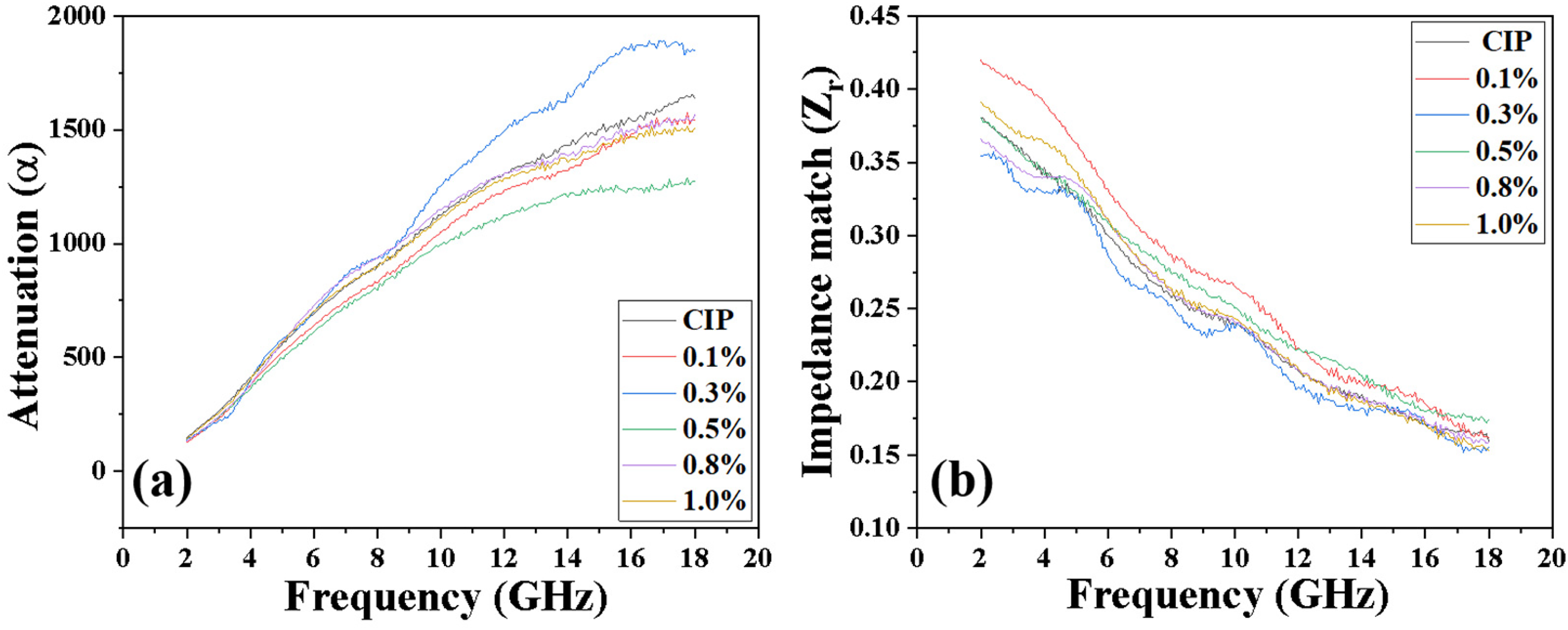
(a) Attenuation constant (
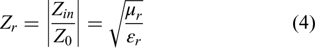
The impedance matching ratio (
The eddy current loss (
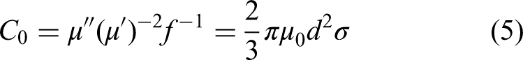
The eddy current loss contribution to the imaginary part permeability is related to thickness (
The values of
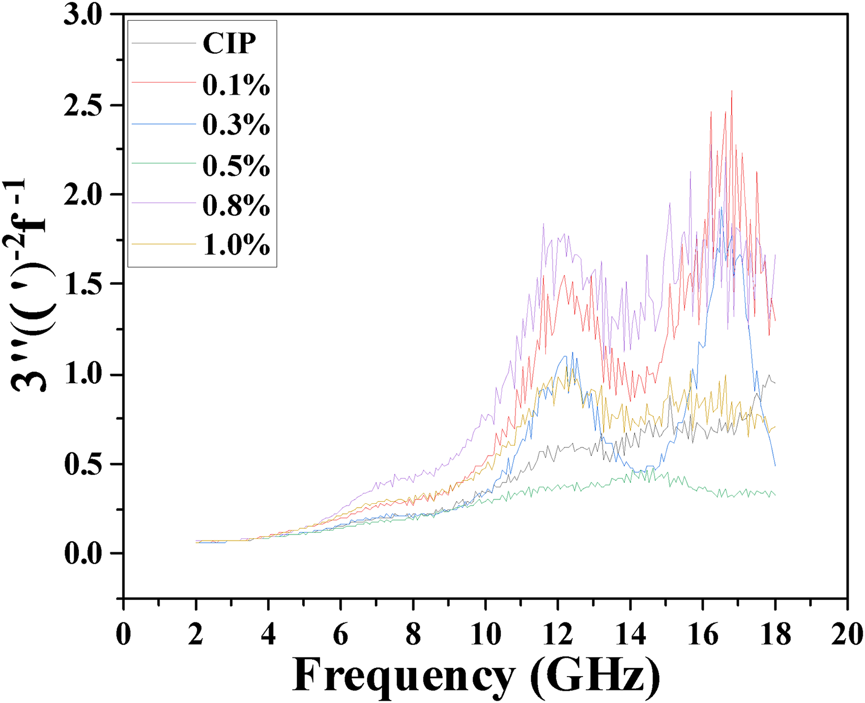
Figure 7 shows the reflection loss (RL) VS frequency for all samples. The RL peaks for all samples are located within S-band. It can be seen from Fig. 7(a) that with the increase in Cu-coated GO doping content, the values of RLmin first decrease and then increase, and the RL peaks shift to the higher frequency. At the thickness of 1.5 mm, the CIP has an RLmin value of −12.13 dB at 3.28 GHz. It can be seen that the composite (0.1 wt% doped) achieves a minimum reflection loss (RLmin) of −12.32 dB at 3.76 GHz. Moreover, the composites (0.3%, 0.5%, 0.8% and 1%) demonstrate higher RLmin values with peaks around 3.28 GHz, as shown in Figure 7(a). An RL value below −10 dB indicates that the material dissipates 90% of the incoming electromagnetic wave energy. 86
The reflection loss of the CIP and CIP/Cu-coated GO composites at thicknesses of 1.5 and 2 mm.
Additionally, at the thickness of 2 mm, the values of RLmin for all samples are below −14 dB within the S-band. It is evident that the doping content does not alter the frequency range of the RL peaks of the CIP, which remains within the S-band. Moreover, the influence of doping content on the values of RLmin is the same as that in Fig.7(a). In contrast to the CIP@TiO2 composite reported by Su et al., 87 which achieved an RLmin of −46.07 dB at 5.04 GHz but required a high filler loading of 50 wt% and a thickness of 3.1 mm. The sample with only 0.1 wt% filler also exhibits good absorptive performance in the S-band (−16.47 dB at 2.8 GHz). It is indicated that the samples in this study possess significant advantages for practical lightweight applications. Lai et al. 88 reported that the CIP/ABS composite exhibits a broader EAB of 4.1 GHz (below −10 dB), the narrower EAB (1.44 GHz) observed in our sample enables more precise absorption in the S-band. In summary, the samples exhibit excellent absorption performance in the S-band.
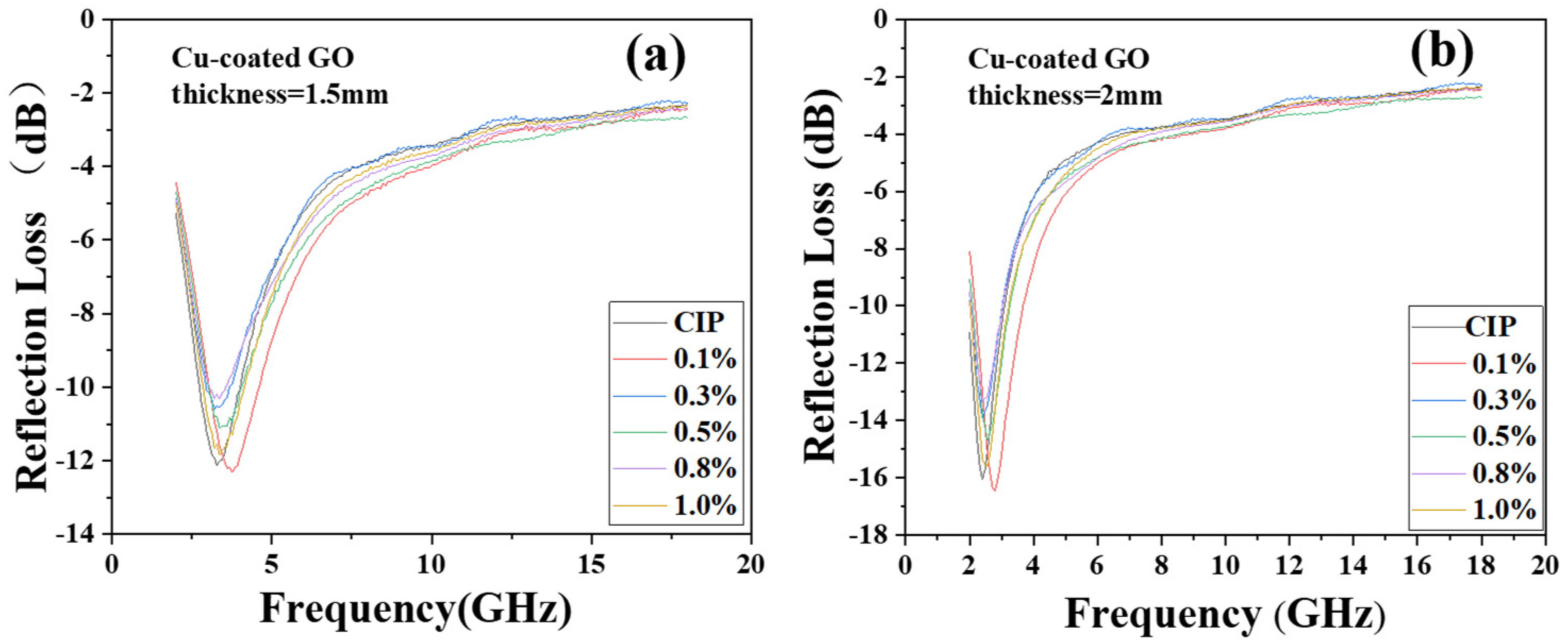
To further explore the RL characteristics of samples at varying thicknesses in the S-band, the 3D relationship map of the RL versus frequency and thicknesses for samples is shown in Fig. 8. The thickness varies from 1.0 mm to 2.0 mm, and the frequency ranges from 2 GHz to 18 GHz. It can be seen that the RL peaks of all the samples decrease with increasing of thickness, which can be explained by the quarter matching model. 89 Additionally, the peak frequency consistently falls within the S-band (2–4 GHz). It is indicated that the absorption properties of the samples can be modulated by varying both the thickness and the content of Cu-coated GO. The properties of the composites facilitate precise control of the wave-absorbing performance in the S-band.
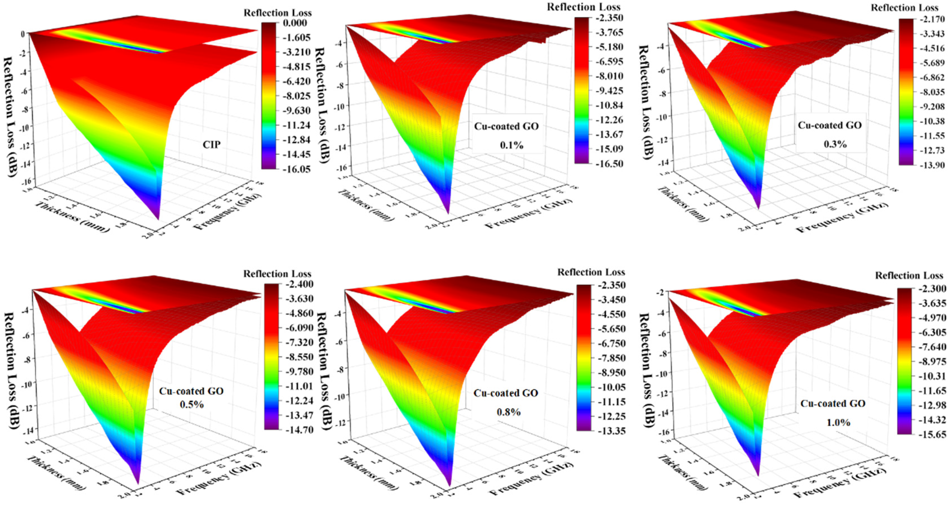
Frequency dependence of RL values at different thicknesses for the CIP and CIP/Cu-coated GO composites: 3D plot.
In wave-absorbing materials, the thickness of the sample is a critical factor influencing the property of wave absorption. In the instance of electromagnetic waves traversing wave-absorbing material, a fraction of the energy is absorbed by the material, while the remainder is reflected. Many studies have demonstrated that the thickness of the sample has a significant effect on the reflection and absorption of electromagnetic waves. For example, the sample with a thickness of 20 mm had the best electromagnetic wave absorption characteristics among the three sets of thickness samples was reported by Xie et al. 90 Chai et al., 91 also reported that the effect of sample thickness on the electromagnetic wave absorption properties of wave-absorbing materials. In general, an increase in thickness of the sample results in an enhancement of the absorption effect. 92 However, this is accompanied by an increase in the weight and cost of the material.
The matching thickness of the wave absorbing material is an important factor affecting the absorption effect. By selecting the correct thickness, the best absorption effect can be realized, and the matching thickness can be calculated by the following equation.
93
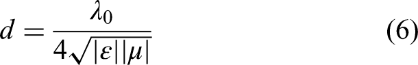
Figure 9 shows the frequency dependence of the matching thickness at 2–18 GHz. The matching thickness of all samples decreases with increasing frequency, with small differences among the curves. Notably, the sample (0.1 wt%) has the largest matching thickness value. This indicates that Cu-coated GO does not significantly alter the matching thickness of the composites.
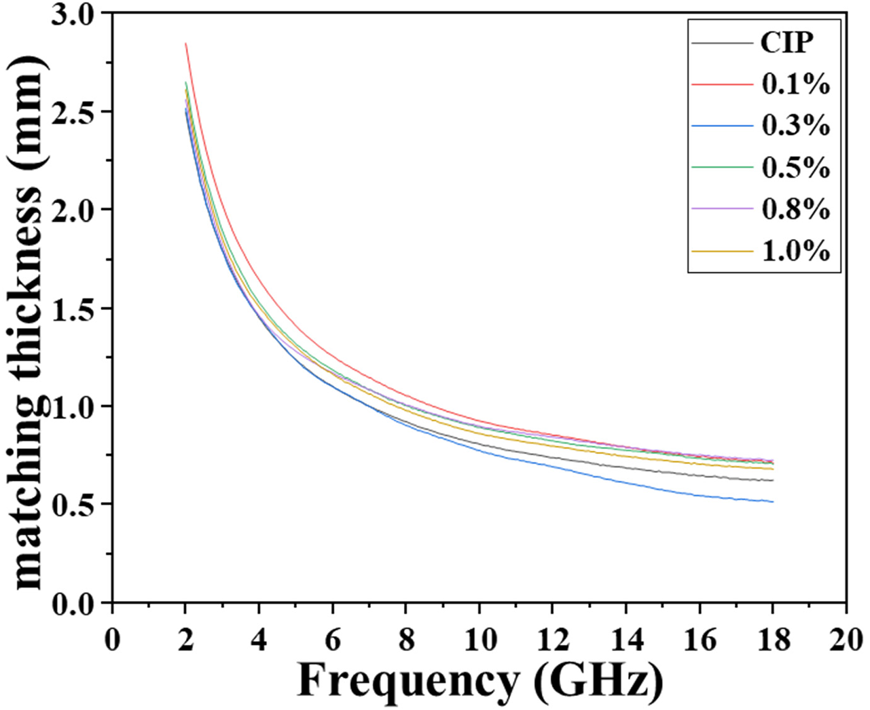
Correlation between the matching thickness and frequency of the CIP and CIP/Cu-coated GO composites.
When the thickness is 1.5 mm, the frequency of minimum RL is 3.76 GHz. From Fig. 9, the frequency corresponding to a matching thickness of 1.5 mm is 4.56 GHz. The significant discrepancy is mainly due to the mismatch at the air-material interface, as the matching thickness is based on ideal reflection conditions (
The thermal conductivity of composites is primarily influenced by the matrix properties and microscopic structures. 95 However, the thermal conductivity can be enhanced by doping fillers that have thermal conductivities higher than those of metals. 96 In this study, Cu-coated GO composites are used as thermally conductive fillers to enhance the thermal conductivity of the composites.
Figure 10 shows a bar graph that depicts the correlation between thermal conductivity and the level of doping content. The thermal conductivity of the CIP is 2.66 W/m·K VS that of composites increases to 2.83, 3.02, 3.25, 3.51, and 3.73 W/m·K, with the doping content of Cu-coated GO is 0.1 wt%, 0.3 wt%, 0.5 wt%, 0.8 wt%, and 1.0 wt%, respectively. It is indicated that the thermal conductivity of the composites is positively correlated with the weight fraction of Cu-coated GO. Although the Cu-coated GO significantly enhanced the thermal conductivity, at the low filler content range (≤1 wt%), the thermal conductivity of the composites remains limited by the relatively low thermal conductivity of the CIP matrix itself (2.66 W/m·K) and the persistent interfacial resistance. 97
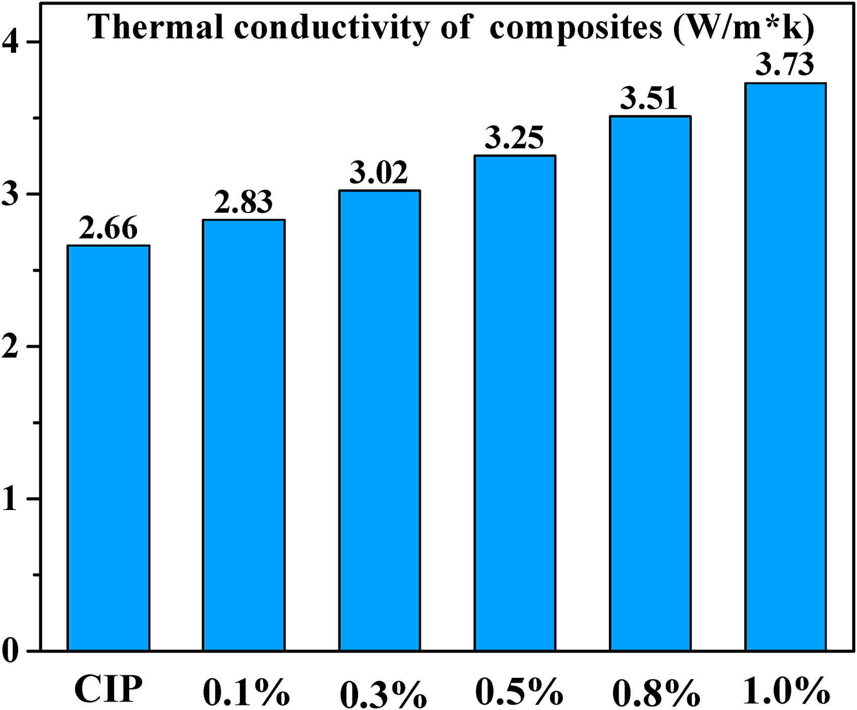
Thermal conductivity of the CIP and CIP/Cu-coated GO composites.
In practical applications, the main approach for enhancing the thermal conductivity of composites is utilizing high filler concentrations (50 wt%–95 wt%). The high content addition of thermal conductivity fillers, such as h-BN, 98 NICFs 99 and Al2O3@AgNPs, 100 can significantly enhance the thermal conductivity of composites. However, the excessive incorporation of thermally conductive fillers in composites may result in the decline in material's processability, mechanical and absorbing properties..101,102 As the thermal conductive wave-absorbing materials, it is should avoid excessively pursuing any single properties.
In this study, the results indicated that the lower filler content (ranging from 0.1 wt% to 1 wt%) could still significantly enhance the thermal conductivity of the CIP/Cu-coated GO composites. Meanwhile, the influence on the absorption properties is negligible. Therefore, the absorbing materials with excellent thermal conductivity and absorption properties have been obtained, achieving an optimal balance between these properties.
Conclusions
In summary, the wave absorption-heat conduction composites have been successfully synthesized by a two-step synthesis route, which combines chemical copper plating with ultrasonic mixing. The microstructure, wave absorption properties and thermal conductivity of the CIP/Cu-coated GO composites were studied. From XRD spectra, the composites all exhibit the
Footnotes
Nomenclature
Author contribution(s)
Funding
The authors disclosed receipt of the following financial support for the research, authorship, and/or publication of this article: National Natural Science Foundation of China (NSFC) (11974188 and 11304159); QingLan Project of Jiangsu Province.
Declaration of conflicting interests
The authors declared no potential conflicts of interest with respect to the research, authorship, and/or publication of this article.
Data availability statement
All data generated or analyzed during this study are included in this published article.