





Abstract
This study investigates the effects of a step aging treatment on 18Ni300 maraging steel aiming to improve ductility while retaining ultra-high strength. The step aging treatment effectively controls the morphology, volume fraction, and size of precipitates and the reversed austenite. The first-stage aging at 480 °C promotes the nucleation of nano-sized η-Ni3Ti precipitates, while the second-stage aging at 560 °C induces the formation of the Laves-Fe2Mo phase and thin-film reversed austenite. Compared with single-stage peak aging, the sample aged at 480 °C for 3 h followed by 560 °C for 1 h exhibited a significant increase in elongation from 3.12% to 6.01%, with a moderate reduction in strength. This enhancement is mainly attributed to the ductility-enhancing effect of thin-film reversed austenite.
Keywords
Introduction
18Ni maraging steels are characterized by ultra-high strength, reasonable ductility, high corrosion resistance, and excellent weldability, which have attracted considerable attention in fields such as aerospace, military equipment, and automotive industry.1–4 Unlike conventional carbon steels, 18Ni maraging steels contain very low carbon (typically <0.01 wt.%), and their strengthening relies on the precipitation of nanoscale intermetallic phases (e.g., Ni3Ti, Ni3Mo, Fe2Mo) rather than carbides.5,6 Extensive studies have been conducted on aging treatment of maraging steels, 7 the peak-aging conditions for commercial grades such as 18Ni200, 250, 300, and 350 have been well established. However, with increasingly harsh service environments and more demanding performance requirements, the major challenge for maraging steels is to enhance ductility while retaining ultra-high strength, thereby achieving an optimal balance between strength and toughness.
Grain refinement is a well-established method for simultaneously improving strength and toughness. 8 Yang et al. 9 reported that rolling reduced the size of prior austenite grains in low-carbon martensitic steel under identical solution conditions, achieving an excellent strength-toughness balance. Similarly, Huang et al. 10 found that cyclic pre-quenching reduced ferrite grain size from 2.4 μm to 1.3 μm in low-alloy TRIP-aided steel, significantly enhancing tensile strength and elongation. These results demonstrate that cold deformation and cyclic heat treatments effectively refine grain size and improve mechanical performance. In addition, tailoring heat treatment to promote the formation of reversed austenite is another effective approach to enhance ductility. 11 Chen et al. 12 studied additively manufactured martensitic stainless steel and revealed that nanoscale reversed austenite dispersed in the martensitic matrix improved strength-toughness combination and fatigue resistance. Zhang et al. 13 examined the effect of aging temperature on 18Ni200 maraging steel and found that higher temperatures increased both volume fraction and size of reversed austenite. An optimal aging temperature enhanced toughness without sacrificing strength, whereas excessive temperatures caused severe strength degradation.
Overall, the combination of cold deformation, cyclic solution treatment, and controlled aging has proven effective in improving the strength and toughness of maraging steels. 14 Notably, volume fraction and size of reversed austenite are highly sensitive to both aging time and temperature, exerting a significant influence on mechanical properties. Merely adjusting a single parameter often fails to achieve desired reversed austenite. Step aging provides a promising solution. The low-temperature stage promotes precipitate nucleation while suppressing growth, and the subsequent high-temperature stage enables uniform growth of these extensively dispersed nuclei. 15 Concurrently, high-temperature aging encourages reversed austenite formation. 16 Although step aging is widely employed in aluminium alloys, 17 its application in maraging steels remains limited. In particular, the evolution of reversed austenite and precipitates during step aging, along with their contributions to mechanical performance, require further investigation.
Therefore, this study employs step aging in combination with cold deformation and cyclic solution treatment to tailor the microstructure of 18Ni300 maraging steel. The microstructural evolution and mechanical behaviour are systematically characterized, and the strengthening and toughening mechanisms are elucidated.
Experimental procedures
Materials
The chemical composition of studied 18Ni300 maraging steel, determined by X-ray fluorescence spectroscopy, is Fe-18.1Ni-10.4Co-4.5Mo-0.66Ti-0.10Al (wt.%). The ingots were sectioned into plates with dimensions of 200 mm × 50 mm × 5 mm. To eliminate residual stresses from prior forging and to prepare for subsequent processing, the plates were annealed at 1100 °C for 20 min, followed by furnace cooling to room temperature.
Figure 1(a) shows the schematic diagram of the heat treatment process. After annealing, the plates were cold-rolled along the longitudinal direction to a total reduction of 30%, achieved through multiple passes with a constant rolling direction. The dilatometric curve of the steel is shown in Figure 1(b). The austenite start (As) and finish (Af) temperatures were measured as 570 °C and 800 °C, respectively, while martensite start (Ms) and finish (Mf) temperatures were 210 °C and 90 °C, respectively. As illustrated in Figure 1(c), three inflection points were observed. The first inflection point, between 480 °C and 570 °C, is related to diffusion-controlled phase transformation caused by precipitation of intermetallic compounds. The second and third inflection points, between 570 °C and 800 °C, correspond to martensite-to-austenite transformation. 18 The presence of two distinct inflection points for austenite transformation is attributed to the inhomogeneous distribution of Ni in the matrix. According to non-equilibrium Fe-Ni phase diagram, increasing Ni content reduces As temperature. Therefore, the second and third inflection points correspond to Ni-rich and Ni-lean regions, respectively.
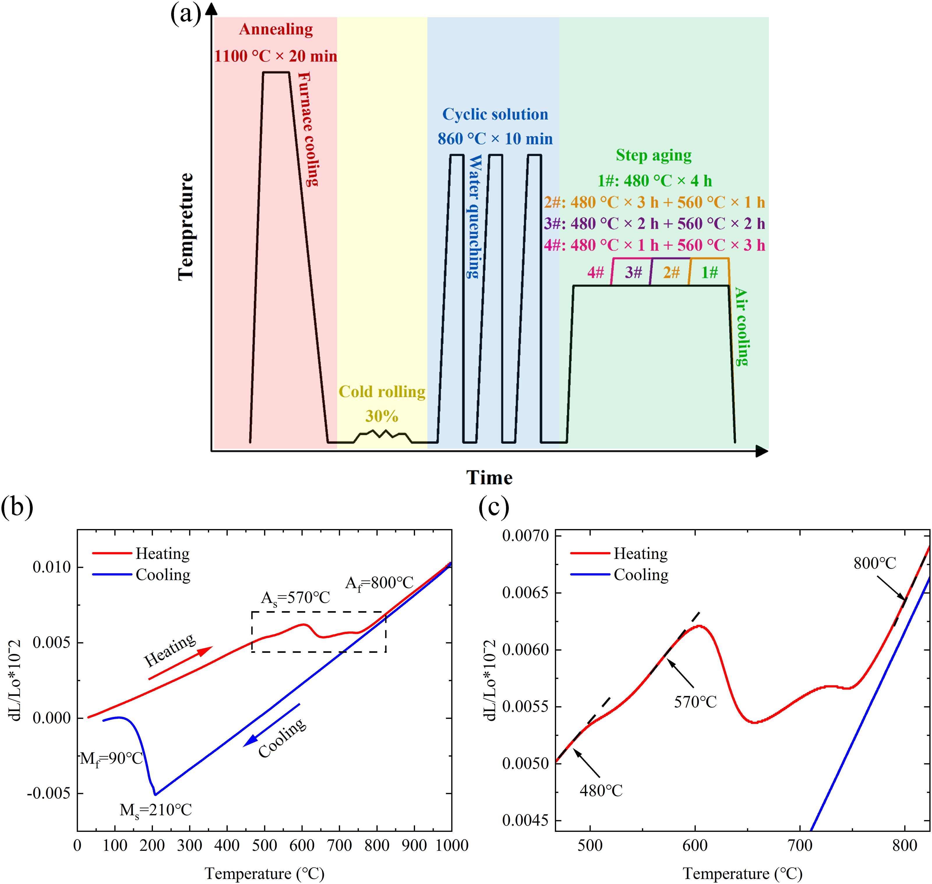
(a) the schematic diagram of the heat treatment process; (b) the dilatometric curve; (c) magnification of the area defined by the dotted square in (b).
Based on the dilatometric results, solution treatment temperature was selected as 860 °C for 10 min, followed by water quenching to room temperature. The cyclic solution treatment was repeated three times. Step aging treatment comprised a first-stage at 480 °C and a second-stage at 560 °C, both followed by air cooling to room temperature. The total aging time was fixed at 4 h to match the conventional peak-aging condition (480 °C for 4 h), thereby minimizing variables. The second-stage temperature of 560 °C was selected because it is slightly below As temperature (570 °C), which is beneficial for forming a small amount of reverse austenite. Four heat treatment schedules were designed: 480 °C × 4 h (Sample 1#), 480 °C × 3 h + 560 °C × 1 h (Sample 2#), 480 °C × 2 h + 560 °C × 2 h (Sample 3#), and 480 °C × 1 h + 560 °C × 3 h (Sample 4#). The detailed specific process parameters are summarized in Table 1.
The detailed specific process parameters.

Mechanical tests
The sampling locations for mechanical and microstructural characterization, as well as the dimensions of room-temperature tensile samples, are illustrated in Figure 2. Room-temperature tensile tests were performed using a Z050 universal testing machine with a crosshead speed of 0.5 mm/min. The samples were machined according to the GB/T228.1-2021 standard into flat dog-bone samples with a gauge length of 20 mm, width of 10 mm, and thickness of 1 mm. The yield strength was determined by the 0.2% offset plastic strain. Three samples were prepared for each condition, and the best result from each group was presented after removing outliers. The fracture surfaces after tensile testing were examined using a Zeiss Ultra Plus field-emission scanning electron microscope (FE-SEM). Microhardness measurements were performed on an HV-1000A microhardness tester with a load of 200 g and a dwell time of 5 s. For each sample, 25 indentations were made in a 5 × 5 grid pattern with consistent spacing. Hardness distribution maps were plotted using Origin software, from which the average values and standard deviations were calculated.
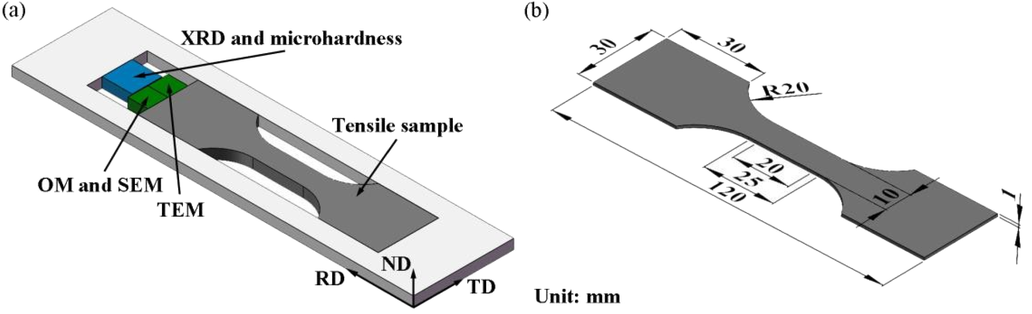
(a) sampling locations for mechanical properties and characterisation samples; (b) dimensions of room temperature tensile samples.
Microstructural characterization
Samples for microstructural characterization were prepared by mechanical grinding and polishing. Microstructural characterization was performed using an Axio Scope A1 optical microscopy (OM) and a Zeiss Ultra Plus scanning electron microscopy (SEM) in backscattered electron (BSE) mode. The OM and SEM samples were etched in 4 vol.% nital for 10–15 s before examination. Quantitative analysis of morphological features was conducted using ImageJ software. Transmission electron microscopy (TEM) was employed using a FEI Tecnai G2 F20 TEM to acquire bright-field (BF), dark-field (DF), and high-resolution TEM (HR-TEM) images. TEM foils were mechanically thinned to approximately 100 μm in thickness, followed by ion milling using a Gatan 695 precision ion polishing system . The acquired TEM data were processed using GMS 3 software. ImageJ software was used to quantitatively analyse the volume fraction of precipitates in TEM images. The precipitates were segmented using a global thresholding method, and the area fraction of the precipitates was measured, which is equivalent to the volume fraction. Phase identification was conducted using an Empyrean X-ray diffraction (XRD) with Cu-Kα radiation at a scanning speed of 10°/min over a 2θ range of 30° to 90°. The volume fractions of martensite and austenite were calculated from the integrated intensities of their respective diffraction peaks using the following equations (1) and (2)
19
:

Results
Microstructure evolution of reversed austenite
The OM and SEM images of four aged samples are shown in Figure 3. The martensitic matrix appeared as dark and grey regions, while the austenite appeared as white regions. In sample 1# (Figure 3(a) and (e)), only a small amount of granular retained austenite (∼1 μm) was observed. This phase was identified as retained rather than reversed austenite, as the aging temperature of 480 °C is far below As (570 °C), precluding its formation. This identification is further supported by its granular morphology, which contrasts with the thin-film morphology typical of reversed austenite. In sample 2# (Figure 3(b) and (f)), a small amount of thin-film reversed austenite formed along the prior austenite grain boundaries. These films were typically 3–6 μm in length and 10–100 nm in thickness. A minor fraction of granular retained austenite also persisted. In sample 3# (Figure 3(c) and (g)), the amount of reversed austenite increased compared to sample 2#, though the dimensions remained similar. In contrast, sample 4# (Figure 3(d) and (h)) exhibited a marked increase in the volume fraction of reversed austenite, which coarsened and aggregated. The films thickness reached 200–300 nm, indicating substantial growth.
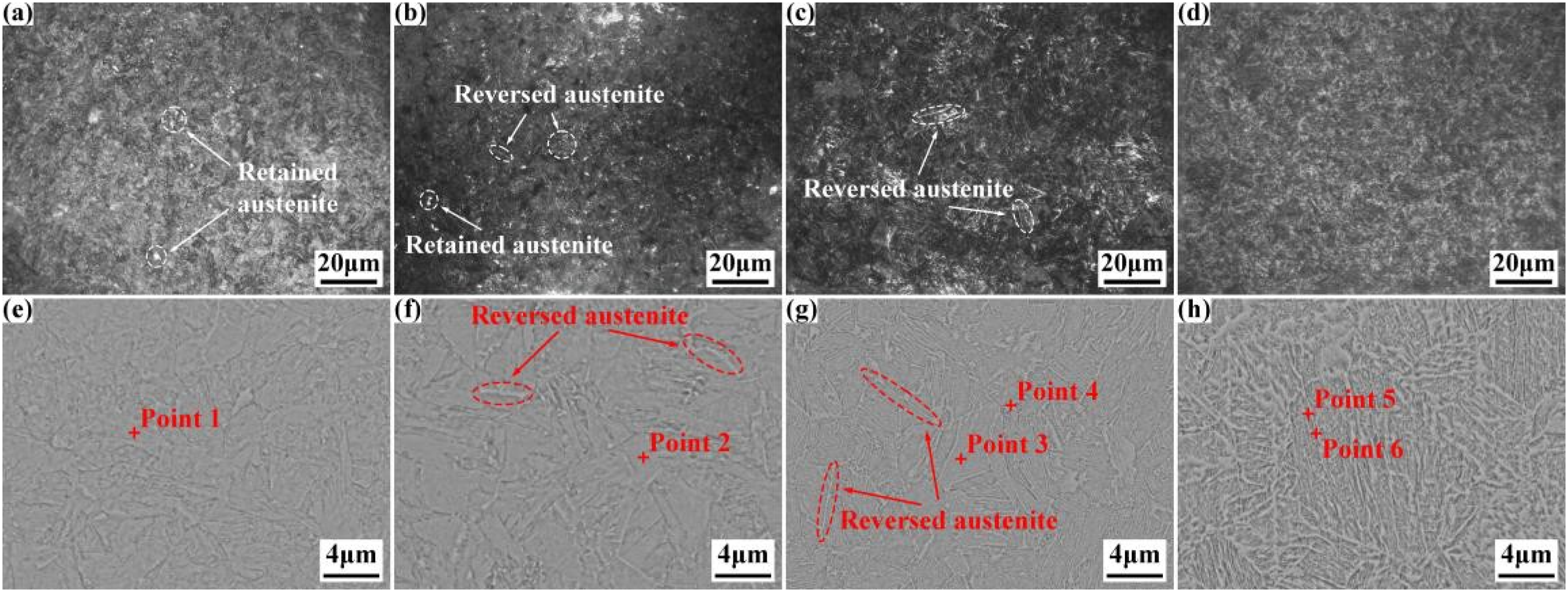
The OM and SEM images of four aged samples (a, e) 1#; (b, f) 2#; (c, g) 3#; (d, h) 4#.
EDS point analyses of the martensitic and austenitic regions are summarized in Table 2. The Ni content in martensite was similar for samples 1# and 2# (18.00 wt.% and 18.59 wt.%, respectively). In contrast, martensite in samples 3# and 4# exhibited slightly lower Ni contents (17.54 wt.% and 17.91 wt.%, respectively). Meanwhile, the reversed austenite in samples 3# and 4# was enriched in Ni (19.38 wt.% and 22.97 wt.%, respectively). This enrichment became more pronounced with prolonged second-stage aging, due to enhanced atomic mobility at grain boundaries that promoted the migration of Ni from martensite into austenite. As an austenite stabilizer, the accumulated Ni at grain boundaries not only locally depressed the As temperature but also facilitated the coarsening of the thin-film reversed austenite. 20
Results of EDS analysis shown in Figure 3.
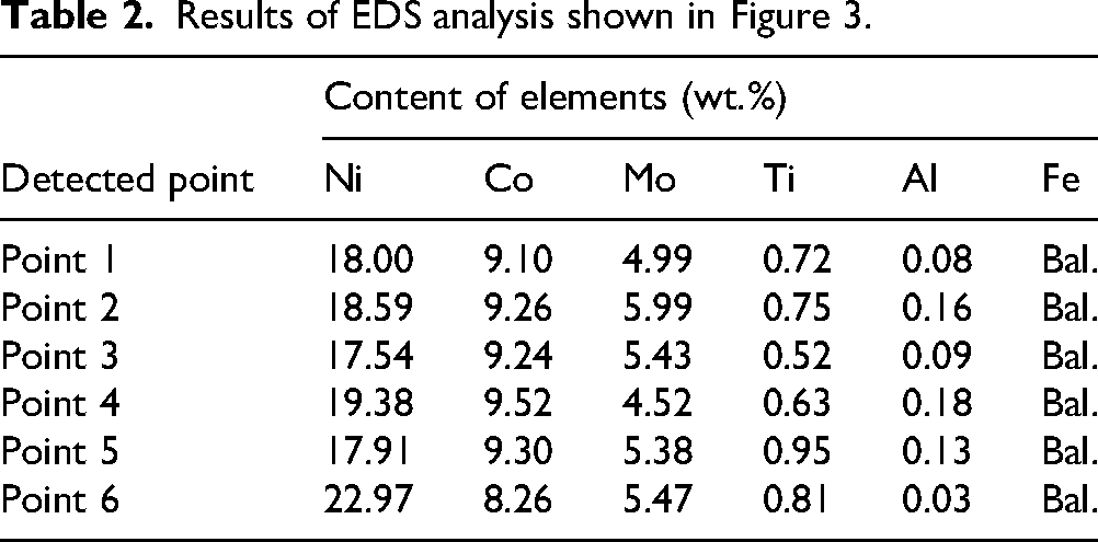
Figure 4 shows the TEM image of reversed austenite in sample 3#. From bright field (BF) image (Figure 4(a)), the film-like reversed austenite exhibited a thickness of approximately 10 nm, and no coarsening was detected. Selected area electron diffraction (SAED) patterns (Figure 4(b)) verified its face centred cubic (FCC) structure. A Nishiyama-Wassermann (N-W) orientation relationship (011)′//(11̅1)γ; [100]γ′// [1̅1̅0]γ was identified between reversed austenite and martensitic matrix.
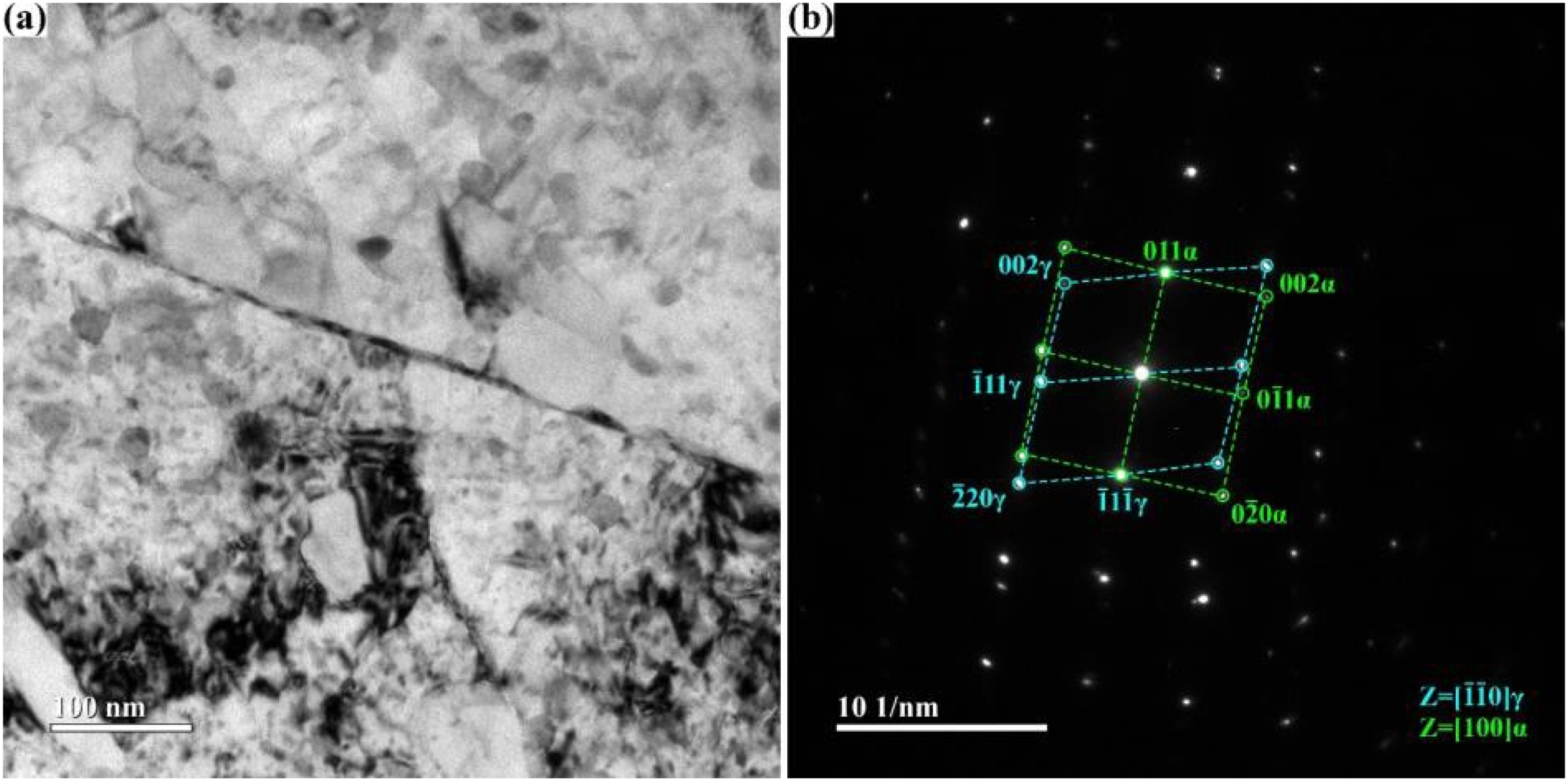
TEM image of reversed austenite in sample 3# (a) BF image; (b) SAED.
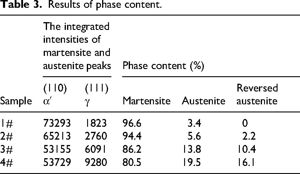
XRD patterns of the four samples are presented in Figure 5. Both martensite and austenite phases were detected, with corresponding main diffraction peaks at (110)α′ and (111)γ. As the second-stage aging time increased, the intensity of austenite diffraction peaks, especially (111)γ, gradually increased. Accordingly, the intensity of martensite diffraction peaks decreased, with the most notable change observed for (110)α′ peak. The calculated phase contents are listed in Table 3. The austenite content increased with prolonged second-stage aging. The 3.4% austenite detected in sample 1# is attributed to retained austenite. By subtracting this baseline value, the content of reversed austenite was estimated to be 2.2% in sample 2#, increasing significantly to 16.1% in sample 4#, which is consistent with the microstructural observations.
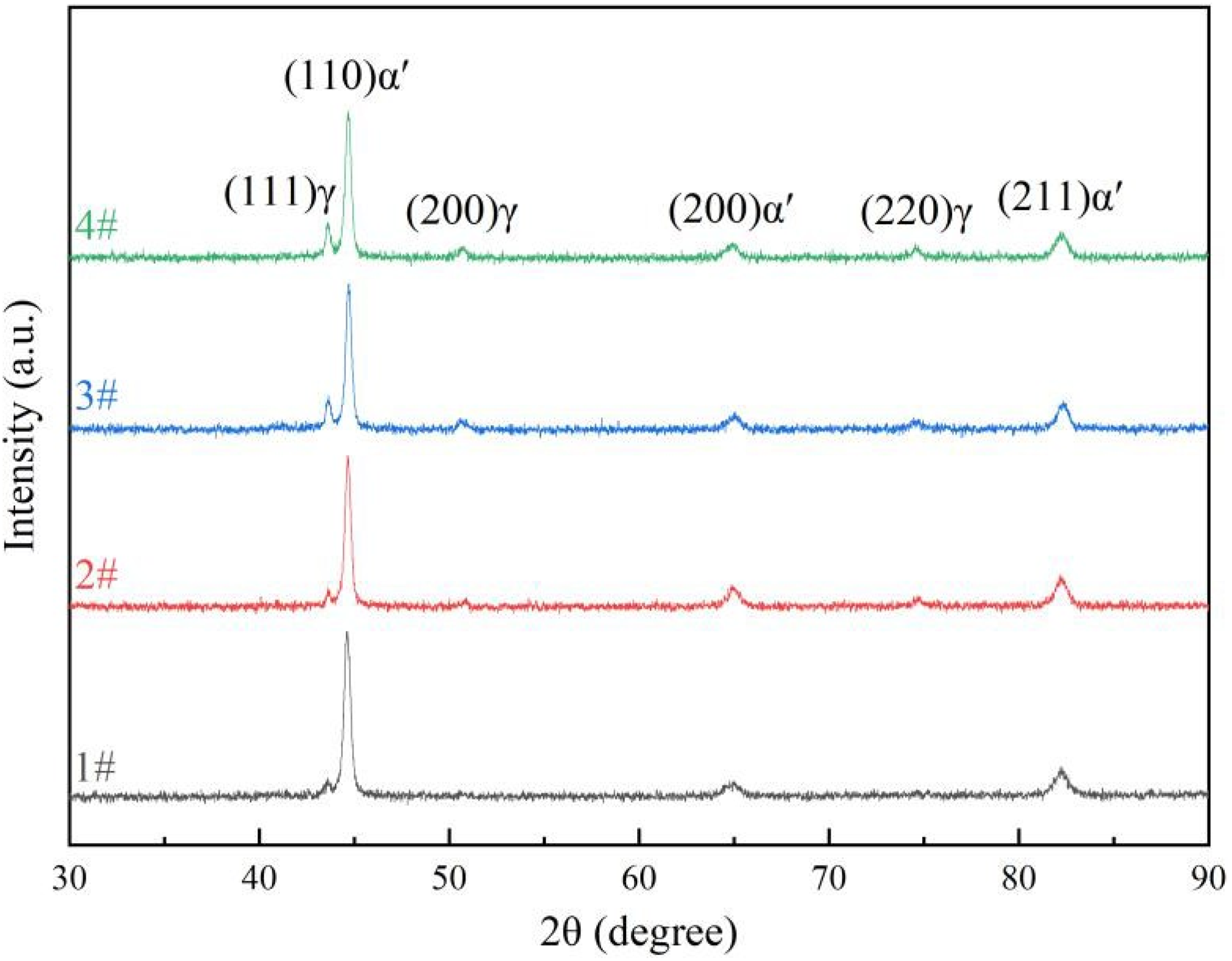
XRD patterns of the four samples.
Results of phase content.
The characterization of precipitation
The precipitation characteristics of samples 1# and 3# were examined by TEM, as shown in Figure 6. In sample 1#, BF image (Figure 6(a1)) revealed numerous rod-like precipitates dispersed within the martensitic matrix, with average length, width, and equivalent circular radius of 21.57 nm, 3.54 nm, and 5.03 nm, respectively. These precipitates were identified as Ni3(Ti, Mo). 21 High-resolution TEM (HRTEM) image of rod-like precipitate are shown in Figure 6(a3). Through measurement of the interplanar spacing, two values of 2.344 Å and 2.225 Å were obtained. Corresponding fast Fourier transform (FFT) image (Figure 6(a4)) confirmed a hexagonal structure. In PDF card of η-Ni3Ti (00-005-0723), the interplanar spacings of (011̅3̅) and (2̅200) planes are 2.347 Å and 2.204 Å, respectively. This is almost identical to the actual measured value. Elemental mapping (Figure 6(c)) further showed enrichment of Ni and Ti and depletion of Fe and Mo in the precipitates, supporting their identification as η-Ni3Ti rather than Ni3Mo.

TEM images of samples 1# (a, c) and 3# (d, b) (a1, b1) BF images; (a2, b2) SAED; (a3, b3) HRTEM; (a4, b4) FFT; (c, d) EDS surface analysis.
In sample 3#, both rod-like and spherical precipitates were observed (Figure 6(b1)). The average equivalent circular radius of the spherical precipitate was 11.10 nm. These precipitates were identified as Laves-Fe2Mo. 22 The average length, width, and equivalent circular radius of the rod-shaped precipitate were 38.29 nm, 5.59 nm, and 8.52 nm, respectively. Figure 6(b3) shows the HRTEM image of the spherical precipitate, the FFT of it (Figure 6(b4)) exhibited a hexagonal lattice structure. Elemental mapping (Figure 6(d)) confirmed that the spherical precipitates were enriched in Mo and depleted in Fe, consistent with Laves-Fe2Mo. Thin-film reversed austenite was also detected, enriched in Ni and depleted in Fe and Co. These results demonstrate that the second-stage high-temperature aging promoted the partial transformation of η-Ni3Ti into Laves-Fe2Mo, concurrently facilitating the formation of reversed austenite.
Mechanical properties and fracture feature
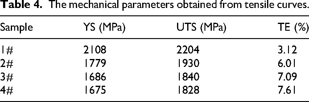
The room-temperature tensile stress-strain curves of the four samples are shown in Figure 7, with the corresponding mechanical properties summarized in Table 4. Sample 1# exhibited the highest strength, with a yield strength (YS) of 2108 MPa and an ultimate tensile strength (UTS) of 2204 MPa, but it possesses the lowest total elongation (TE) of 3.12%. In contrast, Sample 2#, subjected to step aging, shows a YS of 1779 MPa and a UTS of 1930 MPa, while its TE increases significantly to 6.01%. With further extension of the second-stage aging time, samples 3# and 4# exhibited continued reductions in strength but further increases in ductility. Obviously, single-stage peak aging leads to maraging steel exhibiting the highest strength but the poorest ductility. Step aging effectively improves the ductility of maraging steel, but simultaneously reduces their strength.
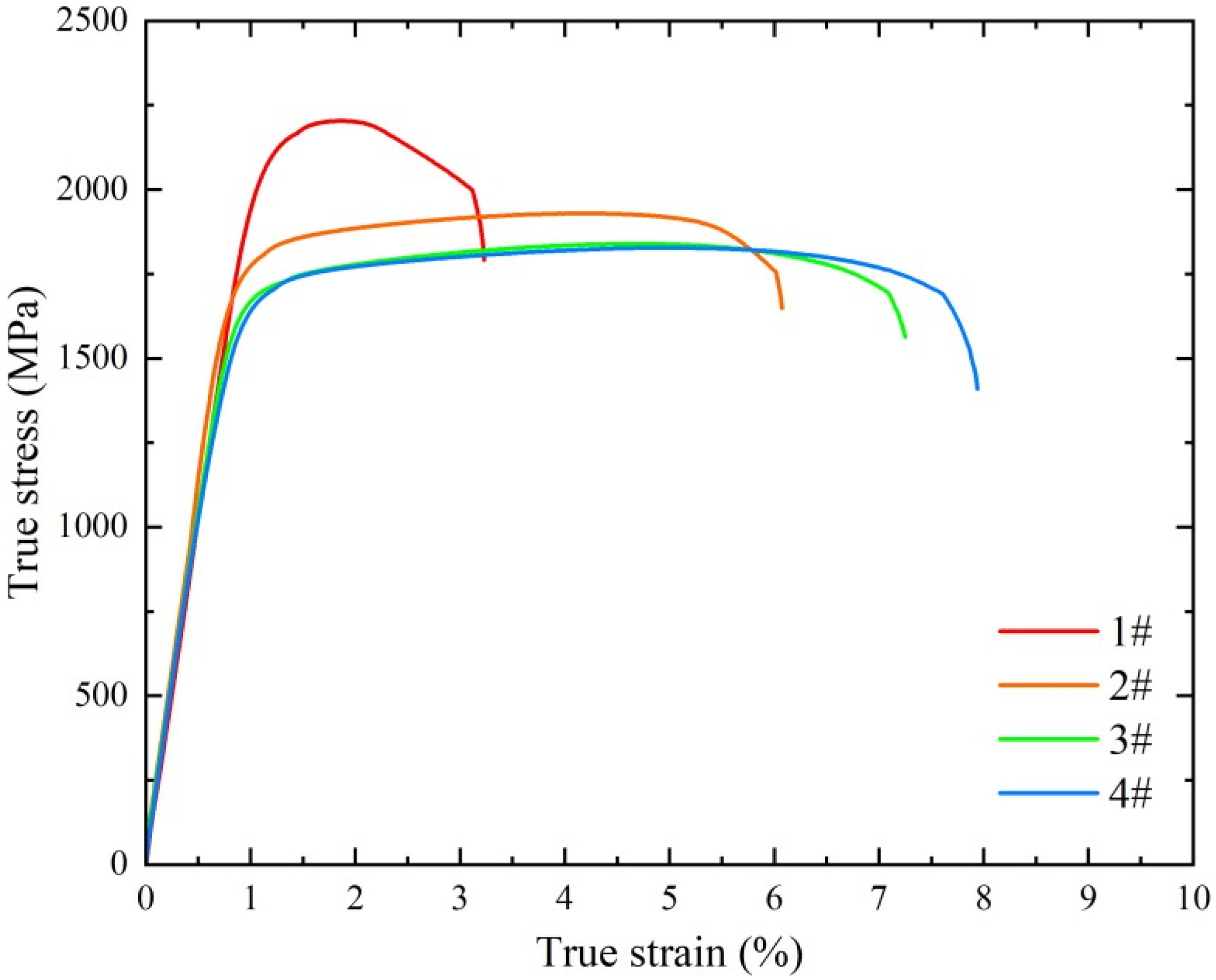
The room-temperature tensile stress-strain curves of four samples.
The mechanical parameters obtained from tensile curves.
The fracture morphologies of the four samples are shown in Figure 8. Sample 1# (Figure 8(a)) exhibited shallow dimples, deconstructive surfaces, and river patterns, characteristic of a quasi-cleavage fracture mode with predominantly brittle features. Sample 2# shows predominantly ductile fracture with numerous dimples, though their sizes were heterogeneous. Sample 3# also exhibited many dimples, more uniform in size than in sample 2#, though some large dimples were present. Sample 4# displays a fully ductile fracture with fine, uniformly distributed dimples formed by microporous polymerization. The fracture morphology is consistent with the tensile results. Furthermore, the fracture behaviour of alloy exhibits significant sensitivity to the content of reversed austenite. Samples 2# to 4#, which include reversed austenite, all demonstrate characteristics of tough fracture.
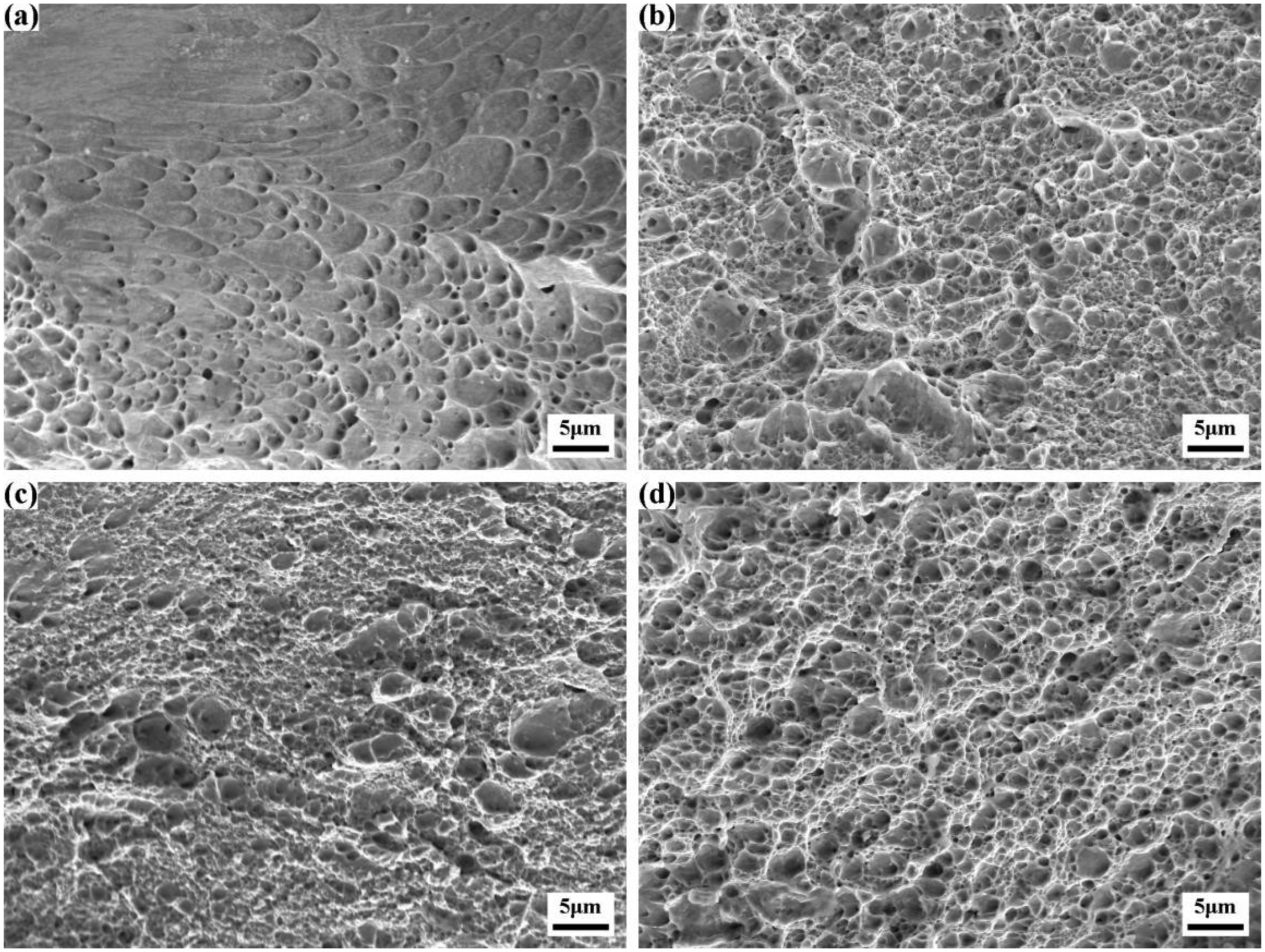
The fracture morphologies of the four samples (a) 1#; (b) 2#; (c) 3#; (d) 4#.
Microhardness
The microhardness distribution maps of the four samples are displayed in Figure 9, with hardness values ranging from 530 to 640 HV. Consistent with the tensile strength trend, the average microhardness decreases with increasing second-stage aging time, from 627.3 ± 5.8 HV in sample 1# (peak-aged) to 549.3 ± 6.4 HV in sample 4#. In all samples, hardness distribution was relatively uniform, with small standard deviations, confirming the homogeneity of microstructure after treatment.
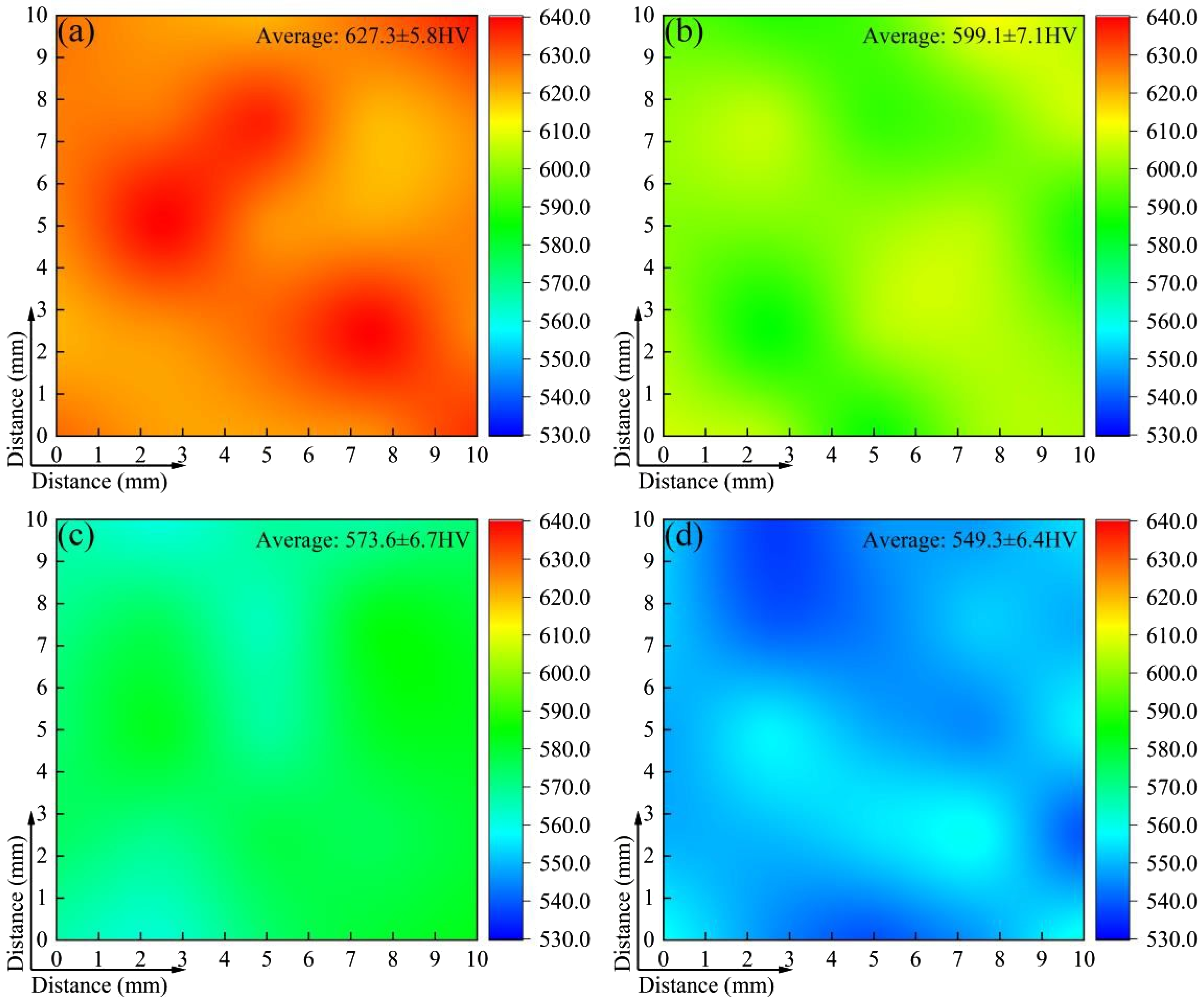
The microhardness distribution maps of four samples (a) 1#; (b) 2#; (c) 3#; (d) 4#.
Discussion
Reversed austenite and precipitates
Step aging was effective in controlling the formation and evolution of reversed austenite. Although the second-stage aging temperature (560 °C) was slightly below As (570 °C), reversed austenite formed due to local Ni enrichment at grain boundaries. Enhanced atomic mobility at grain boundaries relative to the grain interior promoted Ni migration and accumulation in these regions, thereby locally depressing the As temperature. 16 Furthermore, Ni enrichment increases the stacking fault energy (SFE), which suppresses the formation of martensitic shear bands and martensite nucleation sites, thereby stabilizing austenite and allowing it to be retained during subsequent cooling. 23 TEM analysis of sample 3# confirmed that reversed austenite obeyed the N-W orientation relationship with martensitic matrix, which reduces lattice distortion and interfacial energy, facilitating the martensite-to-austenite reverse transformation. 24
No reversed austenite formed in sample 1# due to the low aging temperature. In sample 2#, a small volume fraction (2.2%) of thin-film reversed austenite was detected. The increased aging temperature enhanced Ni diffusion towards grain boundaries. The confined geometry of these boundaries favoured the formation of thin-film reversed austenite. Furthermore, the smaller the martensite plate size, the smaller the dimensions of the resulting film-like reversed austenite. The thin-film morphology benefits the induction of multi-directional deflection at the crack tip, reducing local stress concentration through stress redistribution effects. This mechanism extends the crack propagation path and achieves attenuation of the crack growth rate. With longer second-stage aging, the reversed austenite fraction increased significantly, reaching 10.4% in sample 3# and 16.1% in sample 4#. As a result of prolonged high-temperature aging, the precipitates containing Ni underwent transformation and decomposition. 25 In addition, atomic diffusion was enhanced and Ni segregation was accelerated, leading to the thickening and even blocky morphology of reversed austenite. Coarsened blocky austenite acts as preferential sites for crack initiation and propagation, reducing toughness. Thus, controlling the fraction and size of reversed austenite is critical.
Step aging also significantly influenced precipitation behaviour. During the first-stage low-temperature aging, slow diffusion promoted the nucleation of fine precipitates, particularly at dislocations introduced by cold deformation and cyclic solution treatment. Subsequently, the second-stage higher-temperature aging facilitated the growth of these pre-existing nuclei, leading to an increased total volume fraction of precipitates. Sample 3# contained a larger overall volume fraction of precipitates than sample 1#, but with larger sizes. Importantly, longer second-stage aging led to partial transformation of η-Ni3Ti into Laves-Fe2Mo, as confirmed by TEM and EDS. This process also released Ni into the matrix, increasing segregation at martensite lath boundaries and thereby promoting the formation and coarsening of reversed austenite. Therefore, the second-stage aging time should not be excessively long. Employing a step aging process combining prolonged low-temperature treatment with brief high-temperature treatment may achieve superior results.
Strengthening and toughening mechanisms
The strengthening effect of step aging in maraging steel is primarily derived from precipitation strengthening, wherein the precipitates effectively hinder dislocation motion under applied stress. Concurrently, the formation, transformation, and decomposition of precipitates, as well as the formation of reversed austenite, alter the alloying element content in the martensitic matrix, thereby influencing solid solution strengthening. Furthermore, as the aging temperatures employed in this study exhibited minimal difference (480 °C and 560 °C) and the total aging duration was uniformly 4 h, significant effects on grain size are unlikely. Consequently, the primary focus of this analysis is on the first two factors.
Solid solution strengthening arises from lattice distortion caused by solute atoms, which impedes dislocation motion.
26
Its contribution σss can be estimated using Fleischer equation (3)
27
:
The contributions of solute atoms were calculated from the measured compositions (Table 2). The solid solution strengthening contribution values σss for samples 1# to 4# were 477 MPa, 510 MPa, 472 MPa, and 507 MPa, respectively. Although the latter exhibited a lower Ni content than the former, other elements such as Ti are present in greater quantities. The strengthening constants of Ni and Ti relative to Fe are 334 and 2628. Despite the greater disparity in Ni content compared to Ti across different specimens, the latter still demonstrates a higher solid solution strengthening contribution than the former. In summary, the maximum difference in the solid solution strengthening contribution values for samples 1# to 4# was merely 38 MPa. This indicates that step aging has little effect on solution strengthening.
The ultra-high strength of maraging steel originates predominantly from precipitation strengthening, the efficacy of which depends on the type, size, and volume fraction of the precipitates. The operative strengthening mechanism is determined by the relationship between the precipitate radius R and the Burgers vector b. 29 For precipitates with R < 15b, shearing via the Ashby mechanism is favoured, typically when a coherent/semi-coherent interface is maintained. When R ≥ 15b, the growth of the precipitate disrupts its coherent relationship with the matrix. the loss of coherency makes bypassing via the Orowan mechanism more favourable.
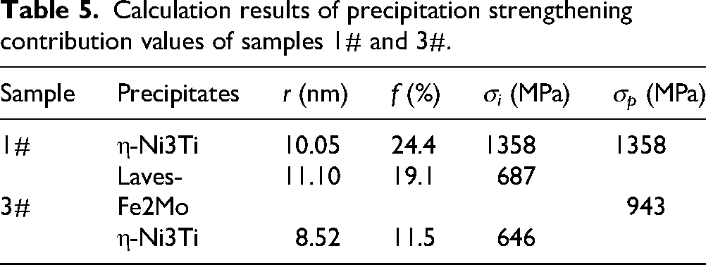
In sample 1#, the η-Ni3Ti precipitates had an average radius of 5.03 nm, slightly above the critical value (= 15b, 3.735 nm), indicating that the Orowan bypass mechanism was dominant. In sample 3#, both η-Ni3Ti and Laves-Fe2Mo precipitates were coarser (8.52 nm and 11.10 nm, respectively), clearly exceeding the critical value, confirming that dislocation bypassing was the primary mechanism. The precipitation strengthening contribution σ
p
can be estimated using the Orowan equation (4)
30
:
Composite strengthening effects should be considered when multiple precipitates are present. The total precipitation strengthening contribution can be calculated using the following equation (5)
31
:
The precipitation strengthening contributions were calculated as 1358 MPa for sample 1# and 943 MPa for sample 3#, as listed in Table 5. Compared to the actual measured yield strengths of sample 1# (2108 MPa) and sample 3# (1686 MPa), the precipitation hardening contributions accounted for 64.4% and 55.9%. Additionally, the difference (415 MPa) closely matched the experimental yield strength difference (422 MPa), confirming that the strength variation among different step aging schedules primarily arises from differences in precipitate. Although the total precipitate fraction in sample 3# exceeded that in sample 1#, coarsening reduced strengthening efficiency, demonstrating the critical importance of size control.
Calculation results of precipitation strengthening contribution values of samples 1# and 3#.
Toughening was strongly associated with the presence of reversed austenite. The thin-film reversed austenite absorbs and redistributes stress, reducing local stress concentrations and delaying crack propagation. Additionally, stresses generated during deformation compensate for the insufficiency of phase transformation driving forces, inducing a part of austenite to martensite transformation. The stresses are thus distributed, thereby enhancing ductility. Sample 1#, which contained only residual austenite, exhibited poor elongation (3.12%). In sample 2#, even a small amount of reversed austenite (2.2%) nearly doubled elongation (6.01%), with only a moderate strength decrease. This demonstrates the strong ductility-enhancing effect of fine reversed austenite. However, excessive and coarsened reversed austenite led to a marked reduction in yield strength in sample 4# (1675 MPa compared with 2108 MPa). This highlights the detrimental effects of overgrowth.
In summary, step aging tailors the balance between strengthening and toughening mechanisms in maraging steel. Optimal results were achieved with a schedule of 480 °C × 3 h + 560 °C × 1 h. It promoted sufficient reversed austenite for ductility without excessive precipitate coarsening or reversed austenite overgrowth.
Conclusions
Based on systematic microstructural characterization (OM, SEM, TEM, and XRD) and mechanical property evaluations (tensile testing and microhardness measurements), the effects of step aging on 18Ni300 maraging steel subjected to cold deformation and cyclic solution treatment were investigated. The following conclusions were drawn.
Step aging effectively controls the formation and evolution of reversed austenite. Even when the second-stage aging temperature is slightly below As, reversed austenite preferentially forms at martensite grain boundaries. Its volume fraction and thickness increase with prolonged second-stage aging. The thin-film reversed austenite significantly improves ductility, whereas excessive coarsening into blocky morphologies severely degrades strength and hardness. Step aging promotes abundant precipitation. The first-stage low-temperature aging favours the nucleation of fine precipitates, while the subsequent higher-temperature stage accelerates their growth, increasing the total precipitate volume fraction. However, prolonged high-temperature aging alters the precipitate population from single-phase η-Ni3Ti to dual-phase η-Ni3Ti and Laves-Fe2Mo, accompanied by coarsening. An optimized schedule involving prolonged low-temperature aging followed by a brief high-temperature treatment yields the most favourable microstructural balance. Peak aging at 480 °C × 4 h resulted in the highest strength (UTS 2204 MPa) and hardness (627.3 ± 5.8 HV) but the lowest elongation (3.12%). In contrast, the step aging treatment of 480 °C × 3 h + 560 °C × 1 h reduced the UTS and hardness by only 12.4% (1930 MPa) and 4.5% (599.1 ± 7.1 HV), respectively, while nearly doubling the elongation to 6.01%. This schedule provided the most favourable strength-ductility balance. The ultra-high strength of maraging steel is primarily derived from precipitation strengthening. Its contribution was calculated as 1358 MPa (64.4% of YS) in sample 1# and 943 MPa (55.9% of YS) in sample 3#. The strength variation under different step-aging conditions is mainly governed by the characteristics of the precipitates, which dictate the efficiency of precipitation strengthening.
Footnotes
Acknowledgements
This work was supported by the National Key Research and Development Program of China (No. 2023YFB3307600), the National Natural Science Foundation of China (No. 52374399) and the Open Fund of the Hubei Longzhong Laboratory (No. 2024KF-15).

Author contribution(s)
Funding
The authors received no financial support for the research, authorship, and/or publication of this article.
Declaration of conflicting interests
The authors declared no potential conflicts of interest with respect to the research, authorship, and/or publication of this article.
Data availability
All data generated or analysed during this study are included in this published article.