
Abstract
A Mg-15Fe (wt.%) metal matrix composite synthesized with powder metallurgy and followed by microwave sintering was studied alongside cryogenic treatment (CT) for the first time. Results revealed that CT was able to alter the microstructure of the composite, with grain refinement (23% reduction in diameter), densification (2.0% increase), and basal texture strengthening. These resulted in enhanced thermal stability (2.4%), elastic modulus (3.2% increase), hardness (10% increase) and yield strength (7.3% increase) at the cost of reduced damping capacity (24% reduction), and ductility (15.4% reduction). Minor thermal changes were also noted of Mg-15Fe with more endothermic nature of CT treated samples. These findings showcase, for the first time, the application of CT in altering the microstructure of a Mg-based Metal-metal composite.
Keywords
Introduction
A primary driver of the escalating climate crisis, especially over the past 25 years, has been greenhouse gas emissions, with the transportation sector playing a major role. Efforts to mitigate these emissions have begun, with one practical approach being the adoption of lightweight materials. Magnesium (Mg) is the lightest structural metal with a density of 1.74 g/cm3 and stands out among materials used in lightweight engineering applications. In comparison, commonly utilized metals such as aluminum (2.7 g/cm3) and titanium (4.5 g/cm3) are significantly denser. Magnesium's exceptionally low density offers distinct advantages, particularly in industries where weight reduction is critical, such as in defense and transportation sector (marine, automotive, space and aerospace). 1 Its application in these sectors enhances performance and reduces emissions by improving fuel efficiency. For instance, in the automotive sector, replacement of components with Mg counterparts can confer weight savings of 22%-70% 2 while an overall reduction in vehicle mass amounting to 10% is expected to increase fuel economy by 6%. 3 Since its industrial introduction in Germany in 1885, magnesium has played a pivotal role in technological advancements, including the production of aircraft during World War II. Today, magnesium-based materials are increasingly employed in diverse fields, from the manufacturing of laptops, automobiles, and aircraft to biomedical applications such as implants and stents, owing to their biocompatibility. 4 Magnesium is also highly recyclable, with reusing scrap magnesium requiring only 5–10% of the energy needed for primary production. 5 This significant reduction in energy consumption contributes to lower greenhouse gas emissions and positions magnesium as a green and sustainable material.
Mg-based alloys and composites are promising materials for multiple industries due to their low density and exceptional strength-to-weight ratio. Alloying elements such as 6 aluminum, zinc, zirconium, manganese, and rare earth metals are commonly used to enhance the properties of Mg. 7 In Mg composites, ceramic particles like alumina, silicon carbide, boron nitride, and carbon-based materials (e.g., carbon nanotubes and graphene) have been incorporated as reinforcements. 8 Metallic elements with high melting points, such as titanium, molybdenum, iron, chromium, and niobium, have also been investigated as effective reinforcements due to their limited to no solubility in magnesium. The incorporation of nanoparticles in magnesium composites, typically in amounts below 3 wt%, offers an effective way to enhance material properties without significantly increasing weight, unlike the use of micron-sized reinforcements which require larger quantities (15–25%). 9
Unlike many metals, Iron (Fe) is renowned for its affordability, strength, and high melting point, and exhibits intriguing characteristics when introduced into a magnesium (Mg) matrix. Despite its inherent advantages, iron has poor solubility in magnesium, meaning only a limited amount of iron can be dissolved into the magnesium lattice. 10 This restricted solubility leads to a system where no magnesium–iron intermetallic compounds are formed, a feature that distinguishes the Mg-Fe alloy system from many other metal combinations. 6 This behavior makes Fe's role in magnesium alloys unique, as the metal primarily reinforces the magnesium matrix without the unwanted side effect of forming detrimental intermetallic phases. 11 This combination of attributes offers an opportunity to enhance magnesium's strength and thermal stability while maintaining structural simplicity, a balance rarely seen in alloy systems. The unique role of iron (Fe) in magnesium (Mg) alloys lies in its ability to strengthen the magnesium matrix without introducing the complexities typically associated with intermetallic compound formation. 10 The addition of Fe to Mg has shown promising potential for various applications, including biomedical implants hydrogen sensing and storage, and electromagnetic shielding (in the X-band range, 8.2–12.4 GHz which is critical for military and communication applications), attributed to ability to effectively lower electrical conductivity while also increasing magnetic strength, 12 highlighting its versatility in advanced technological fields. 13
Cryogenic treatment (CT) of metals has been practiced for nearly 300 years, mostly on steels. 14 This method involves exposure to low temperatures, with past works utilizing liquid nitrogen (LN) and dry ice as the medium, achieving temperatures of −196 °C and −84°C respectively. 15 Studies of such treatment on other materials16,17 have resulted in positive outcomes such as increased wear resistance, 15 creep resistance, 18 and increased hardness 14 on the materials.
With this in mind, this study examines, for the first time, the impact of CT (via LN exposure) on the physical, microstructural, and mechanical properties of a Mg-Fe metal-metal composite.
Experimental Procedure
Synthesis
Powder metallurgy was used as the synthesis method, with pure magnesium (Merck Group, Darmstadt, Germany) in the form of powder (60–300 microns size) with a purity of >98.5% and iron powder (74 micron) from Alfa Aesar GmBH and Co (Haverhill, MA, USA) with >99% purity used as raw materials for this study. Figure 1 below shows the morphological features of the powders.
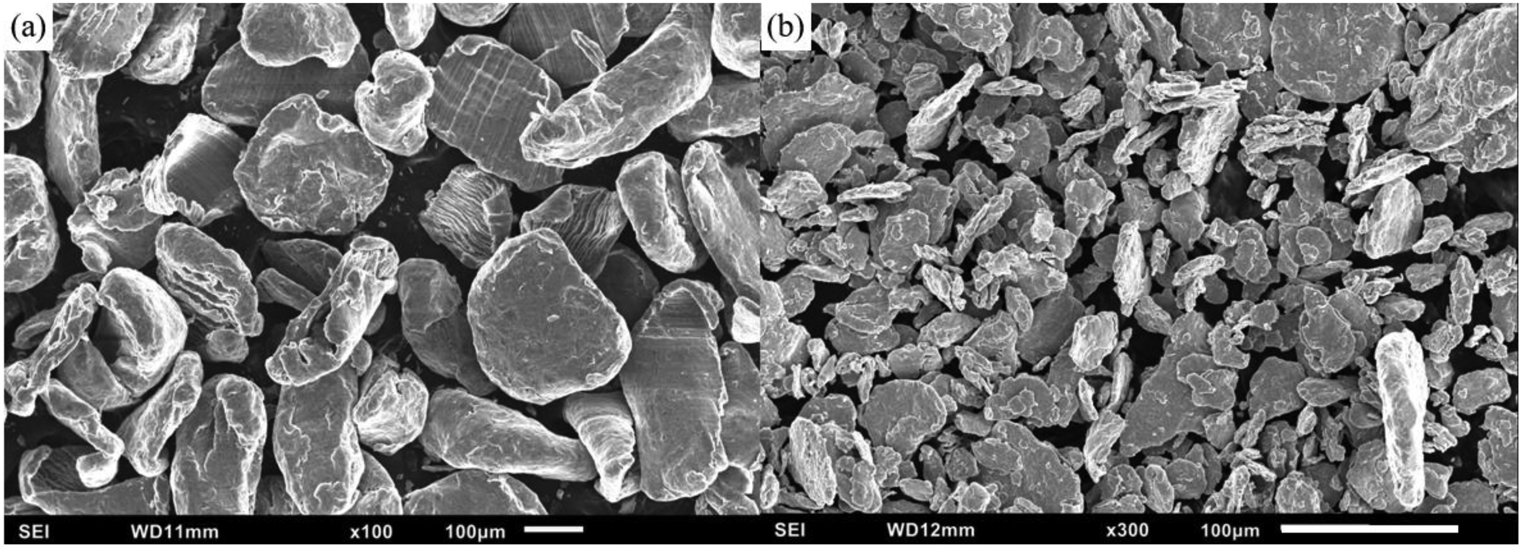
Scanning electron micrograph of Mg and Fe powders used in this work.
A Maxstech Roller Mixer (Maxstech Technology (S) Pte Ltd, Singapore) was used to mix the magnesium and iron powder at 200 RPM for 1 h. Afterwards, this powder mixture was compacted using a hydraulic press with compaction pressure of 600 psi and a holding time of 2 min. This resulted in a billet of 35 mm diameter. The billet was then sintered at 640 °C in a microwave (Sharp model R-898C(S), Sharp Corporation, Osaka, Japan) for 24 min at full power (900 W) and then subjected to hot extrusion with parameters of 400 °C soaking for 1 h followed by hot extrusion at a die temperature of 350 °C with a die diameter of 8 mm resulting in an extruded rod.
Cryogenic treatment
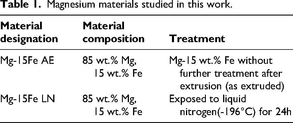
After the hot extrusion process, two representative sets of samples were obtained from the extruded rod; one was set aside and left untreated to serve as a baseline in this study, designated AE (As-extruded) and the other was exposed to LN (− 196 °C) for a duration of 24 h; this duration was selected as previous studies on Mg-materials had utilized this CT duration with positive results19,20 and literature suggests that 24 h’ duration is sufficient for the desired effects of CT on metallic materials (enhanced mechanical properties and microstructural changes) to fully manifest,14,21,22 with longer exposure durations not conferring further benefits. Certain material characterization before and after CT were conducted on the same samples (density, microstructure, damping, and hardness tests as elaborated in section 2.3 below). Table 1 outlines the materials studied in this work.
Magnesium materials studied in this work.
Physical characterization
Five samples from each material were measured for their density with the use of an AD-1653 Density Determination Kit and a GH-252 electronic balance (A&D Company, Limited, Tokyo, Japan). Samples’ weights were measured both in air and when submerged in de-ionized (DI) water at room temperature. The density of each material was then derived using the Archimedes principle.
Microstructure
General microstructure
Flat and parallel samples were fine-finished with 0.05 micron alumina suspension. The Hitachi S-4300 FE-SEM (Field Emission SEM, Hitachi Ltd, Tokyo, Japan) equipped with EDS (Energy Dispersive Spectroscopy) was employed to characterize the microstructure of the materials.
X-Ray diffraction
X-ray diffraction (XRD) studies were performed along the longitudinal direction using the Shimadzu LAB-XRD-6000 automated spectrometer (Shimadzu Corporation, Kyoto, Japan) with Cu Kα radiation of 1.54 Å wavelength, scanning range of 2Ө = 10° to 80° (Ө represents the Bragg angle), and a scan speed of 2° min−1.
Grain size analysis
Polished flat and parallel samples were etched with 5% citric acid for a duration of 30 s. Optical images of the etched samples were taken using a Leica DM2500 Optical Microscope (Leica Microsystems (SEA) Pte Ltd, Singapore) and the average grain sizes of each were evaluated using MATLAB (version R2013b) in accordance with standard E112–13 (2021)
Thermal response
Thermogravimetric analysis
A sample of approximately 20 mg mass from each material was subjected to temperatures of 30 °C to 1400 °C at a rate of 10°C / min in purified air at a flow rate of 50 mL / min with the use of a Shimadzu DTG-60H Thermogravimetric Analyser (Shimadzu Corporation, Kyoto, Japan) to characterize ignition response.
Differential scanning calorimetry
A sample approximately 20 mg in mass from each material was subjected to heating from 30 °C to 600 °C at 5 °C / min in Ar gas at 25 mL / min with use of a Shimadzu DSC-60 Differential Scanning Calorimeter (Shimadzu Corporation, Kyoto, Japan) to characterize thermal response.
Coefficient of thermal expansion
A sample 5 mm in length from each material was heated from 50 °C to 400 °C at 5 °C / min in Argon gas at 0.1 L/min with use of a TMA PT1000 Thermo-mechanical analyser (Linseis Messgeraete GmbH, Selb, Germany) to characterize the coefficient of thermal expansion (CTE).
Mechanical response
Damping behavior and elastic modulus
A sample of approximately 50 mm length of each material was selected for damping characterization. Each sample was subject to impulse excitation and its vibration response measured with a microphone. IMCE RFDA software (IMCE, Genk, Belgium) was used to analyze the collected data to characterize damping properties.
Microhardness
A Shimadzu HMV-2 automatic digital microhardness tester (Shimadzu Corporation, Kyoto, Japan) with a Vickers indenter was used to characterize hardness. This was conducted with an indentation load of 245.2 mN, a dwell time of 15 s, and a minimum of 15 readings per sample were taken in accordance with ASTM standard E384–08
Compression testing
Quasi-static room-temperature compression testing was carried out using an MTS E44 fully automated servo hydraulic mechanical testing machine (MTS Systems, Eden Prairie, MN, USA) at a strain rate set at 8.3 × 10⁻⁵ s−1. A minimum of three samples with a length-to-diameter (L/D) ratio of 1 were tested according to ASTM E9–09.
Fractography
Compressive fractography was performed on post-compression fracture surfaces with the SEM and images of the fracture surfaces were taken to gain insight into fracture behavior.
Results and discussion
Physical characterization
From Table 2, LN exposure has resulted in densification (increase of 2%), attributed to several mechanisms: 1) large compressive stresses within the materials from thermal contraction promoting microscopic deformation, causing the material to deform inward into existing pores. 14 2) Significant increase in the generation of dislocations in the material,23–25 which may sink and collapse into existing pores, reducing porosity and subsequently increasing density.26,27
Density values of materials in this work.
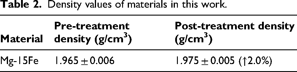
While the increase in density was just on the verge of standard deviation overlap, readings both before and after CT were obtained from the exact same samples – the standard deviation is thus due to the small variances in individual sample readings and the densification statistically significant.
Microstructure
General microstructure
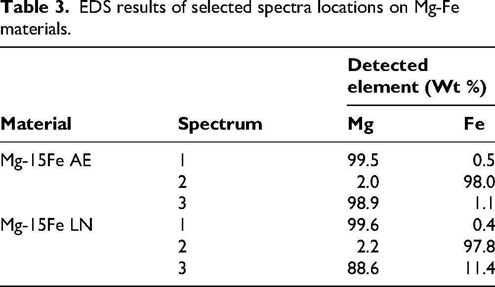
From the SEM images and EDS results in Figures 2 and 3 as well as Table 3, Fe particles were present and evenly distributed against the Mg-matrix, showcasing the low solubility of Fe in Mg and lack of intermetallics in the Mg-15Fe system.
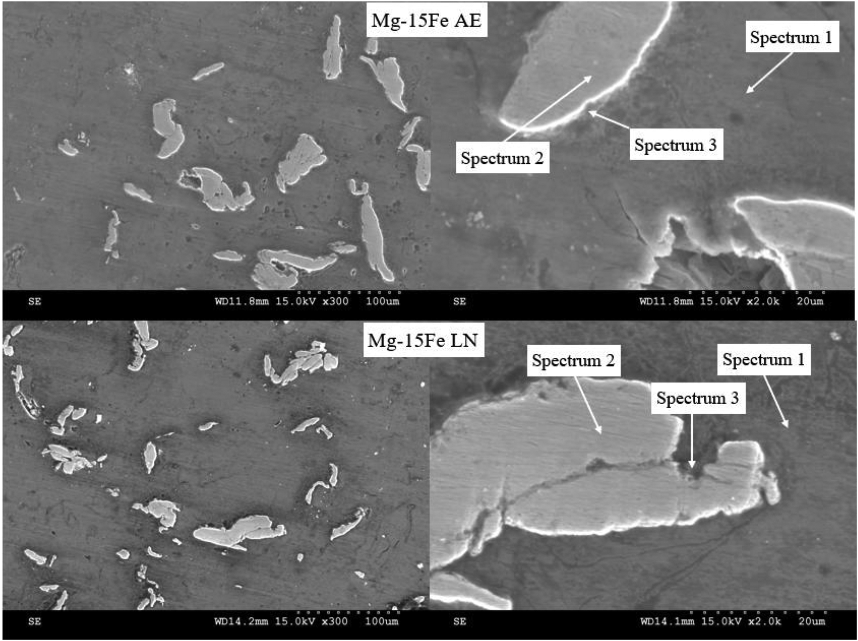
Scanning electron micrograph of Mg-Fe materials in this work.
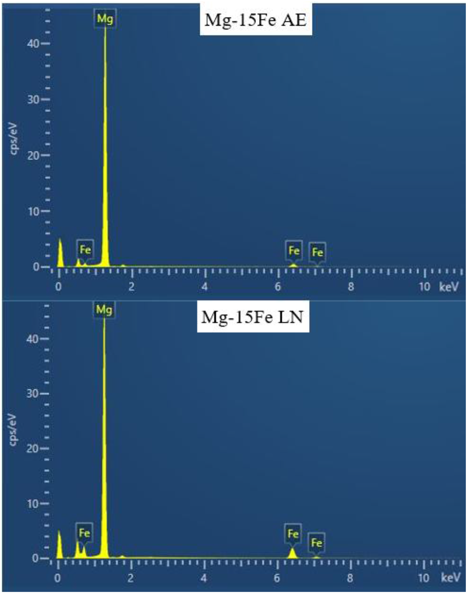
EDS spectra of Mg-15Fe materials in this work (based on lower magnification image).
EDS results of selected spectra locations on Mg-Fe materials.
X-Ray Diffraction
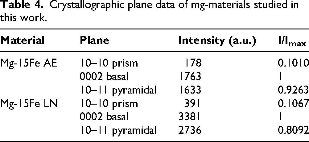
Figure 4 and Table 4 shows the results of the X-ray characterizations, with the peaks being identified against JCPDS cards found in the PDF-5 + database (Mg: 00–004–0770, Fe: 00–006–0696).28,29 The basal texture of Mg was observed to be dominant, 27 with basal texture strengthening being observed in Mg-15Fe LN.
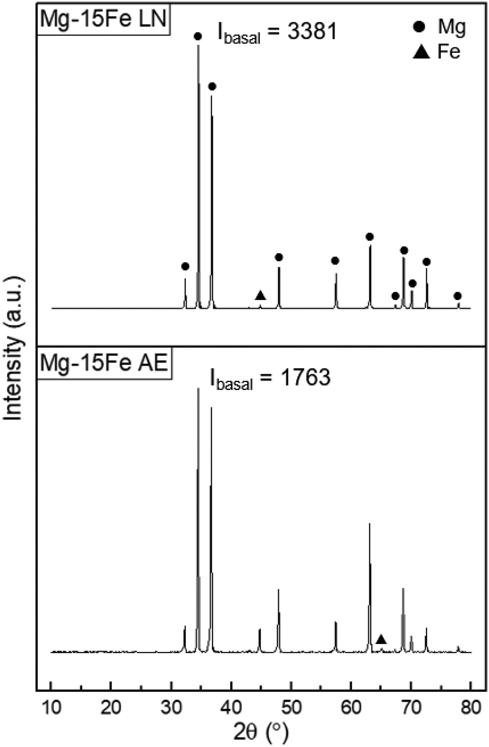
X-ray diffractograms of Mg-materials studied in this work.
Crystallographic plane data of mg-materials studied in this work.
Grain size analysis
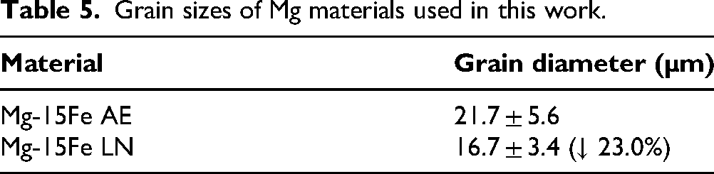
Significant grain refinement was observed following CT, with 23.0% reduction in average grain diameter after exposure to LN as seen in Table 5 and Figure 5. This is attributed to increased level of twinning (seen in Figure 6) and inward movement of grain boundaries under compressive stresses brought upon by CT, as previously observed with Mg-based alloys undergoing CT 30
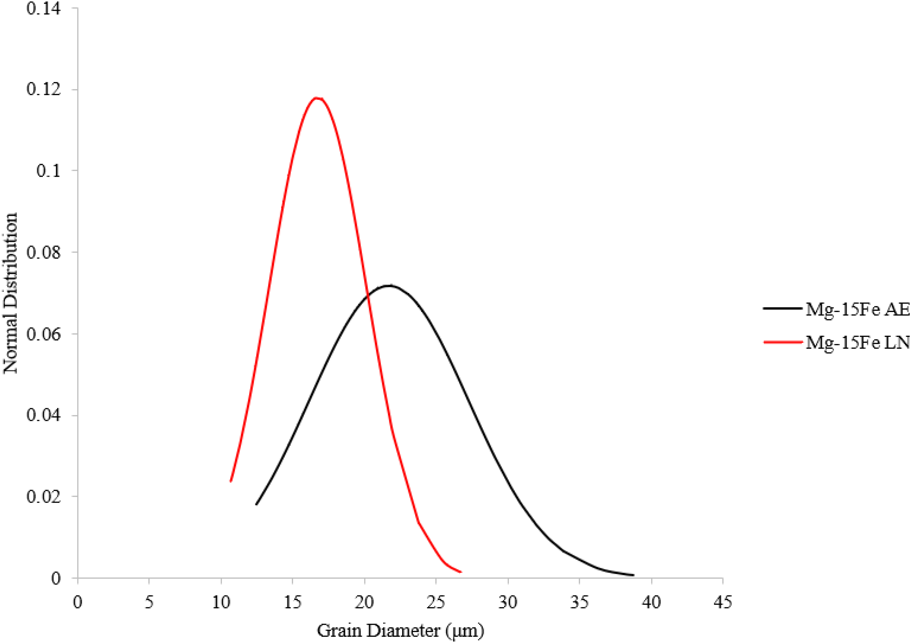
Grain size distribution curves of Mg-materials in this work.
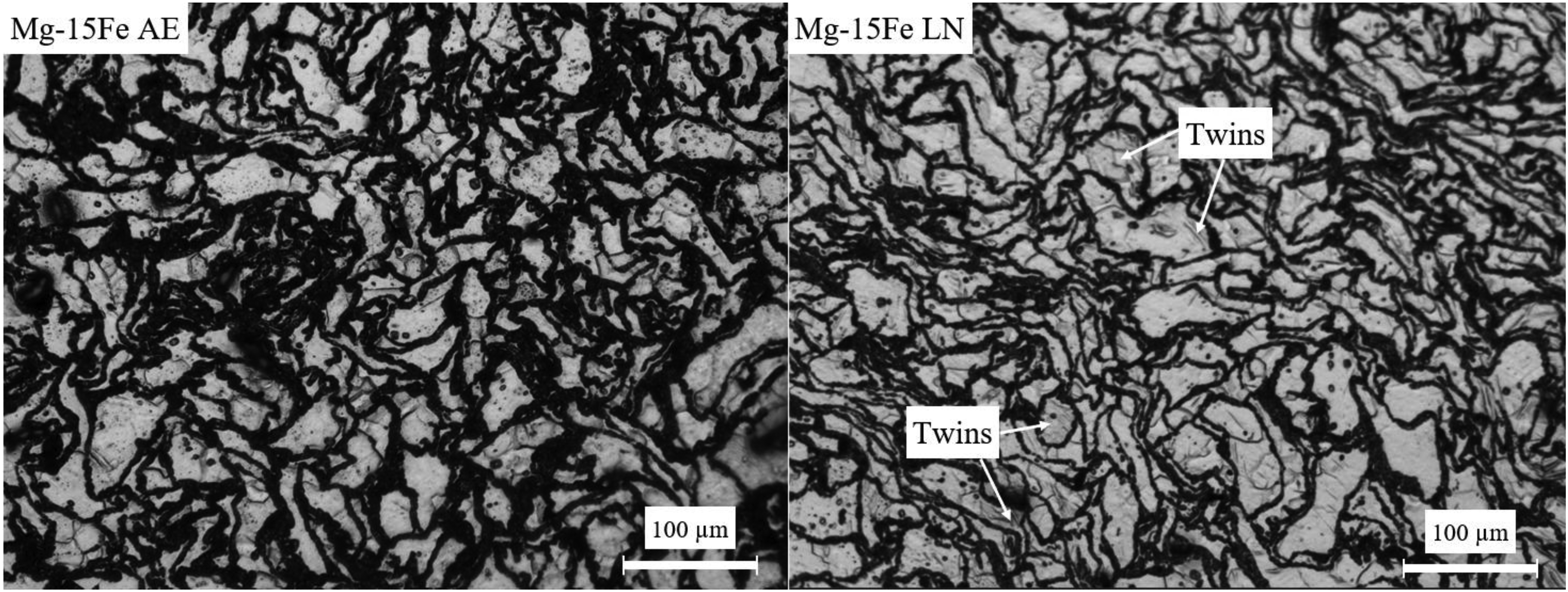
Grain micrographs of Mg-materials in this work, showing the increased twinning after CT.
Grain sizes of Mg materials used in this work.
As with the density test conducted previously, the grain size measurements were conducted on the same sample both before and after CT; an effect of note was the reduction in standard deviation after CT, visually represented in Figure 5 (taller, narrower size distribution curve). This shows that despite the standard deviation overlap existing, the actual statistical overlap for grain diameter is not very large, with a significant reduction in grain diameter observed. To further note that the shift in grain sizes (Figure. 5) towards lower range convincingly indicates the capability of CT in changing the microstructural characteristic of Mg-Fe metal-metal composite.
Thermal properties
Ignition response
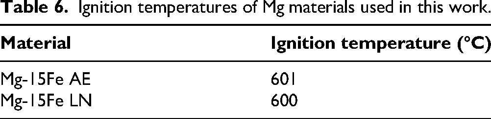
Table 6 and Figure 7 shows the ignition response of the materials. Ignition temperature was taken at the point just before a sudden rise in temperature is observed, with CT not having a significant effect. No significant change in ignition temperature was observed after LN exposure, with less than 1% change in ignition temperature which is likely to be within the error limits of measurement.
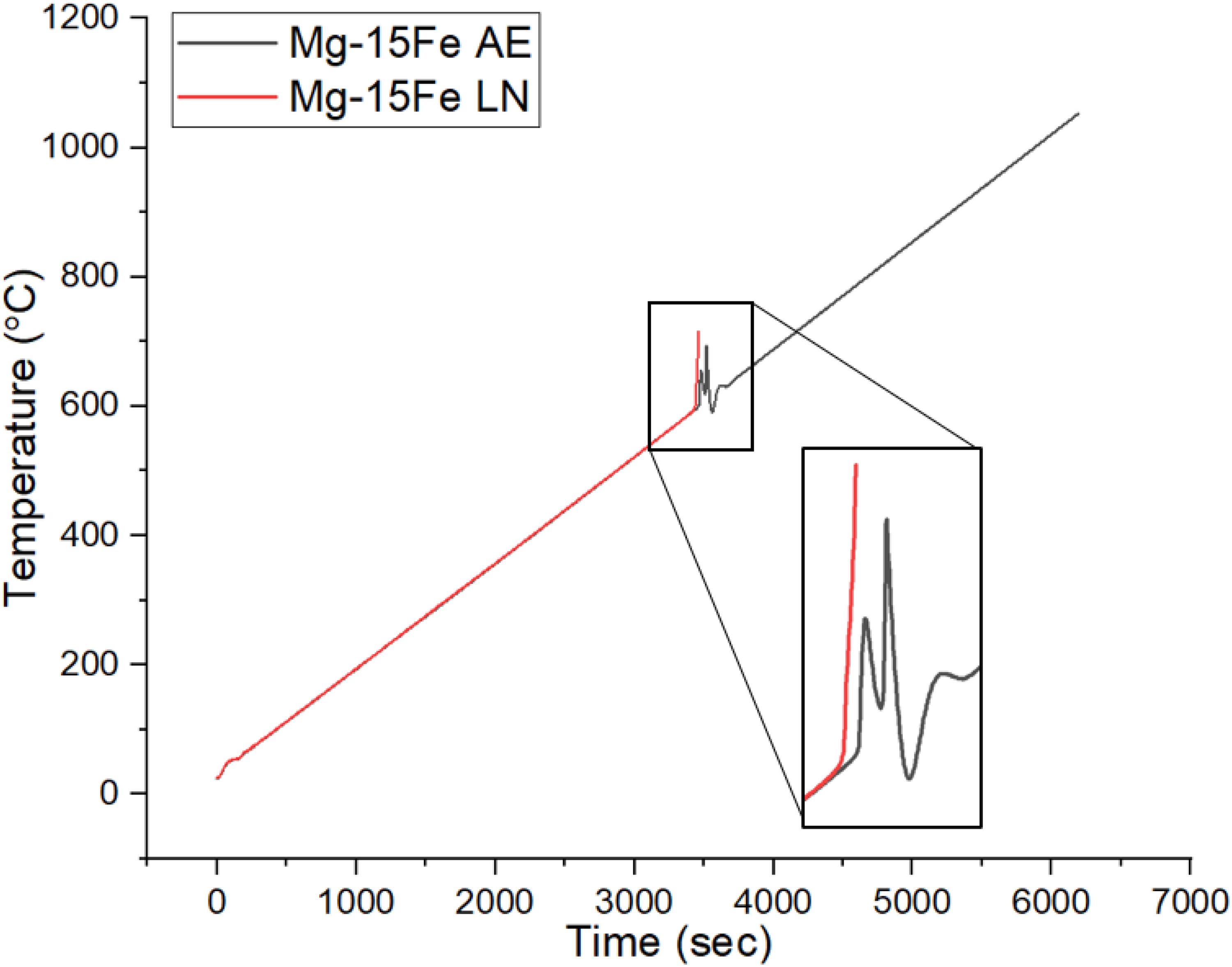
Ignition response of Mg-materials in this work.
Ignition temperatures of Mg materials used in this work.
Thermal response
Figure 8 shows that LN-treated Mg-15Fe experienced a more endothermic trend, indicating higher specific heat capacity; this is attributed to the densification of the materials after CT. The capacity to absorb more energy may also be attributed to the mitigation of defects that are additionally created due to CT. Further work is continuing in this area.
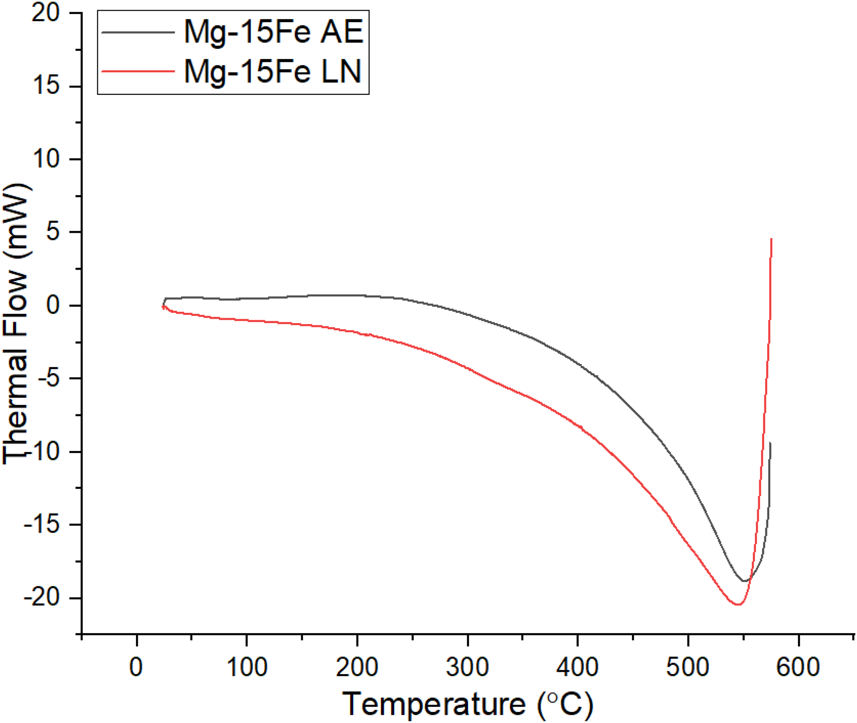
Thermal response of Mg-materials in this work.
Coefficient of thermal expansion
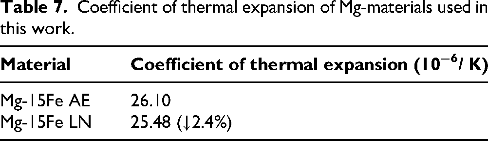
The CTE of the materials studied in this work are summarized in Table 7. A marginal decrease in CTE was observed for Mg-15Fe (by 2.4%). This is likely due to scattering of phonons at grain boundaries (the area of which increased following CT), by the increased dislocation density, 31 and reducing thermal conductivity across the bulk material. 32
Coefficient of thermal expansion of Mg-materials used in this work.
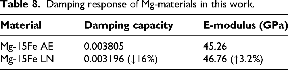
Damping response of Mg-materials in this work.
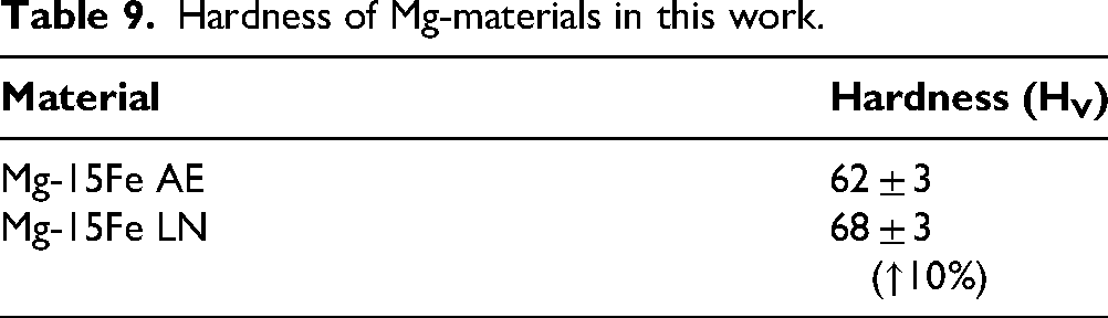
Hardness of Mg-materials in this work.
Mechanical response
Damping behavior and elastic modulus
CT resulted in worse damping response (Table 8) due to the increase in density (and subsequent reduction in porosity). This infers reductions in air pockets and void volume — physical features that are known to enhance damping properties in Mg-based materials. 33 Accordingly, this results in inferior energy dissipation capabilities. 34
A marginal improvement in Young's modulus is observed after CT. This not only aligns with the effect of CT on the microstructure and compressive response of Mg-SiO2 nanocomposites, 19 but is also supported by literature indicating improved elastic modulus with decreasing porosity.35,36
Microhardness
Exposure to LN directly confers 10% enhancement in hardness of Mg-15Fe (Table 9), attributed to grain refinement (in accordance with Hall-Petch relationship),37,38 increase in dislocation density, and reduced porosity owing to densification as previously observed. 27 The increase in grain boundary area and dislocation density acts as additional barriers to slip, deformation, and dislocation motion, 39 increasing the hardness of the materials after CT.
As was previously observed with the density measurements of this material, the increase in hardness is statistically significant as not only did the standard deviations not overlap (average hardness before and after CT were exactly 2 standard deviations away), these were also obtained on the same sample before and after CT within a short timeframe, minimizing other external factors that may have influenced this property.
Compressive response
Figure 9 and Table 10 summarizes the compressive response of Mg-Fe composites, with the average 0.2% yield strength increasing for Mg-15Fe LN at 7.3% above its as-extruded counterpart. This enhancement in yield strength can be attributed to grain refinement through the Hall-Petch relationship37,40 and the increase in friction stress due to additional defects generation due to CT as the CTE (CTEMg = 26.0 × 10⁻⁶ K−1 and CTEFe = 11.8 × 10⁻⁶ K−1) and elastic modulus (EMg = 45 GPa and EFe = 204–212 GPa) of magnesium and iron are significantly different.41–44
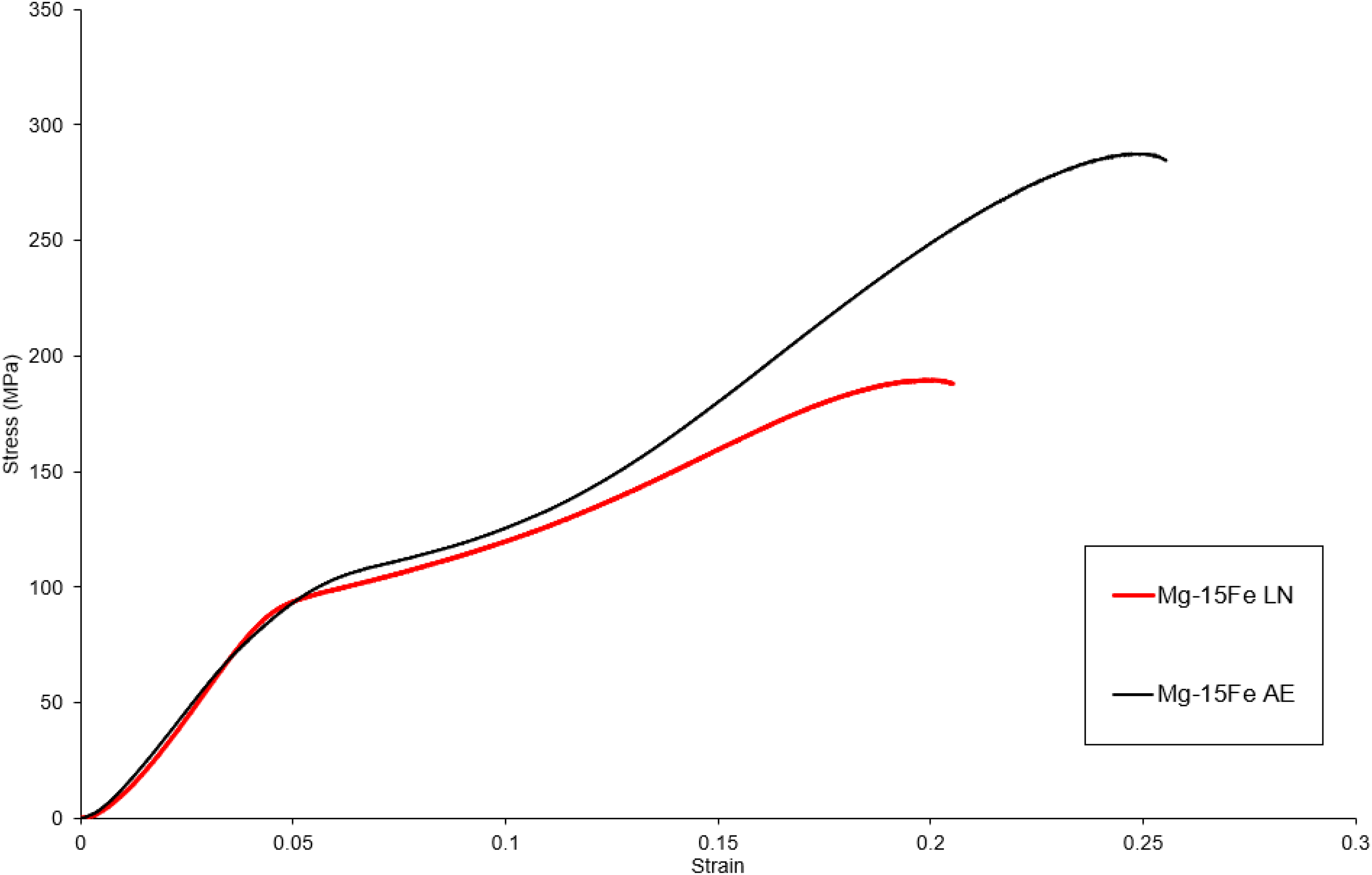
Representative stress-strain curves of Mg-materials in this work.
Compressive properties of Mg-materials in this work.
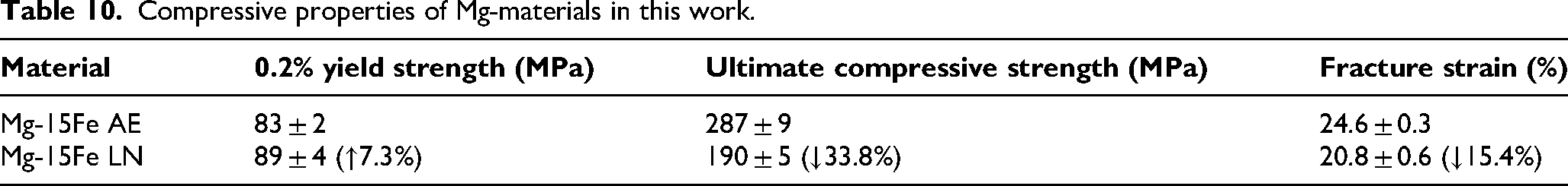
However, there was a compromise of properties related to the plastic region (UCS and ductility, by 15.4% for the latter). This was due to the aforementioned difference in CTE of Mg and Fe which, under the compressive loads and subsequent deformation generated during CT, 14 would result in defects and thermal cracks, lowering UCS and ductility despite the enhanced yield strength. 45 In addition, aside from grain refinement and increase in dislocation density, there was a conspicuous lack of strengthening mechanisms such as precipitation of secondary phases as previously observed with steels and other Mg-alloys due to the Mg-Fe system not having any known secondary phases. 21 Furthermore, the strengthened basal texture of Mg-15Fe LN as revealed by XRD analysis (nearly double that of its untreated counterpart) also contributes to the increased yield strength at the cost of decreased ductility, 46 underscoring the multi-faceted nature of mechanisms affecting individual properties of a given material.
A visual examination of the micro-composite samples post-compression reveals that fractures occurred at an angle of approximately 45° relative to the compression axis (Figure 10). At the micro scale (Figure 11), fracture surfaces of LN-treated materials exhibited more cracks, confirming the compromise between grain refinement and cracking susceptibility previously outlined. The presence of cracks on LN treated samples also validates the lower UCS and ductility displayed by LN treated samples (Table 10).
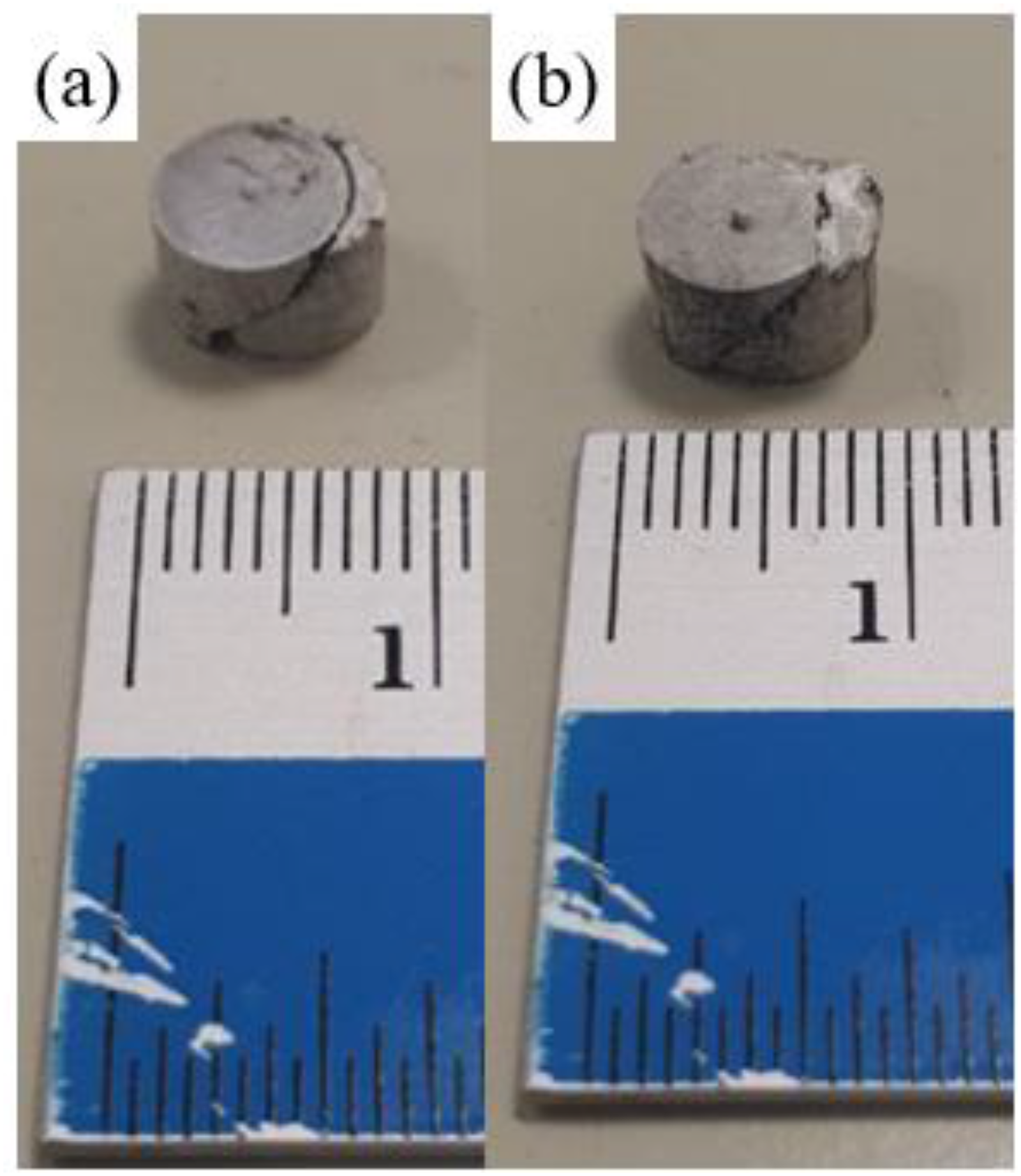
Macro-scale photographs of: (a) Mg-15Fe AE and (b) Mg-15Fe LN post-fracture.
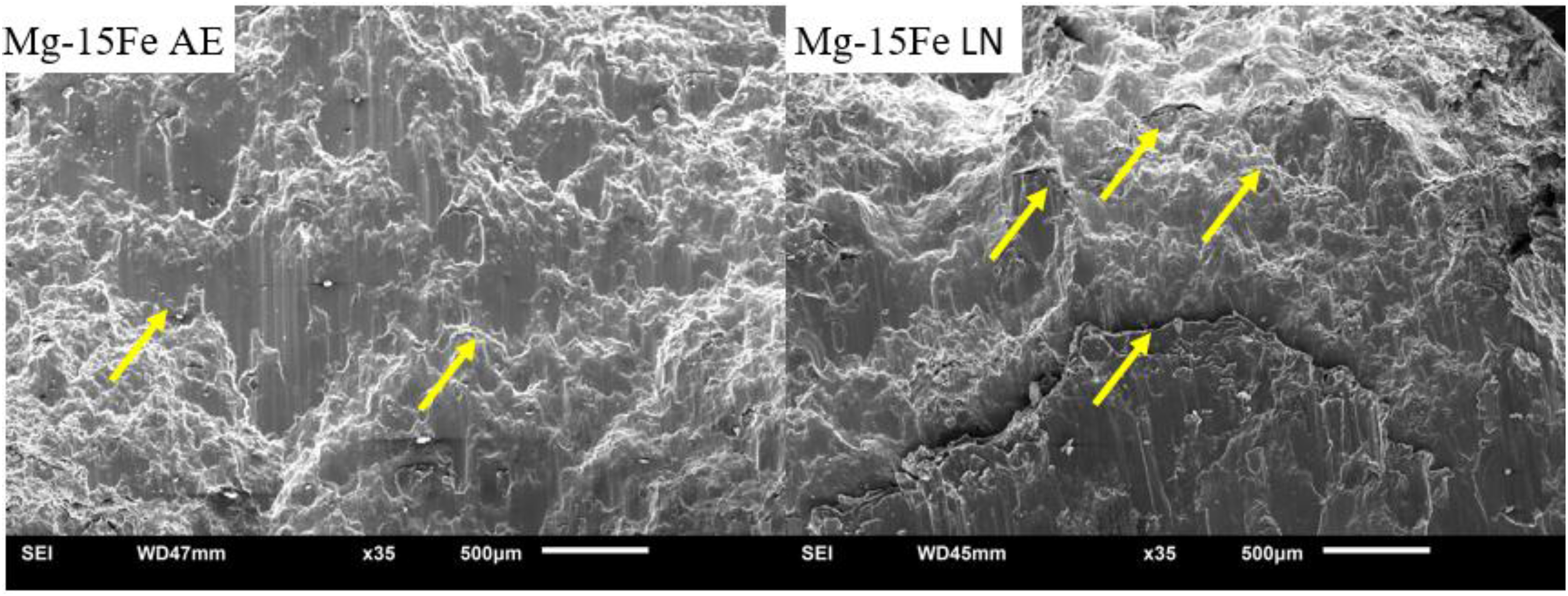
Fractographs of Mg-materials studied in this work, with cracks indicated by arrows.
Conclusions
In conclusion, LN exposure of Mg-15Fe resulted in microstructural and property changes:
Densification occurred after CT, with a 2.0% increase in density Mg-15Fe after LN exposure. Grain refinement was observed for Mg-15Fe, with a 23.0% reduction in average grain diameter and the grain distribution curves shifting to lower grain sizes. Basal texture strengthening was observed with Mg-15Fe after LN exposure. Enhancement of Young's modulus was observed (3.2% increase) for Mg-15Fe after CT. Mg-15Fe experienced a 10% increase in hardness after CT. Mg-15Fe experienced 7.3% increase in yield strength whilst also undergoing a 15.4% decrease in failure strain after CT, highlighting the compromise between properties (strength and ductility) as a result of basal texture strengthening.
These findings showcase the ability of CT to alter the microstructure of and hence affect the resulting material properties of Mg-based materials; that said, anomalous effects were observed specially in context of reduced ultimate compressive strength and ductility, underscoring a compromise in properties. Such compromises, though not ideal, may be acceptable if the intended application use-case of the material warrants the benefits. For example, in applications where plastic loading is not expected, the increased yield strength and hardness would be of benefit since the treated material would both be more resistant to deformation or damage and can sustain higher loading before yielding, delaying or possibly even stopping the onset of plastic deformation.
In addition, due to the exploratory nature of the work, there also lies room for further optimization of CT parameters – while the duration was based on literature, there also exists further possibilities with regards to exposure temperature, which may pose better alternatives due to the ductility compromise observed earlier (arising from the cracks, possibly due to thermal cracking owing to the very low temperatures reached in LN immersion). Such options may include − 20 °C, − 50 °C, and − 80 °C which, while still sub-zero, are less extreme in nature and can result in varying effects on individual properties. 20 Another possibility would be cyclical CT, where the cycle of CT and return to ambient temperature is repeated, as had been done recently on Mg-ZnO nanocomposites. 47
Footnotes
Acknowledgments
The authors would like to acknowledge Mr. Juraimi Bin Madon for the extrusion work and Ng Hong Wei for the assistance with DSC, CTE and TGA testing.
Author contribution(s)
Funding
The authors received no financial support for the research, authorship, and/or publication of this article.
Declaration of conflicting interests
The authors declared no potential conflicts of interest with respect to the research, authorship, and/or publication of this article.