






Abstract
Al MMCs reinforced with rice husk fly ash (RHA) were fabricated by stir casting at 760 °C using pure commercial Al 1050 (CP-Al) alloy with 5 wt.% and 10 wt.% reinforcement. The addition of RHA refined the microstructure, reducing the average grain size from ∼55 µm to 33 µm, while suppressing columnar dendritic growth through particle-assisted nucleation. Mechanical properties improved, with the 10 wt.% RHA composites showing a 77% increase in hardness and a 61.25% increase in UTS, resulting from combined grain refinement & thermal mismatch effects. XRD and SEM results confirmed the interfacial stability of Al and RHA. The composites also exhibited superior wear resistance under loads of 20–60 N due to the load-bearing and wear-inhibiting role of RHA particles.
Introduction
Agricultural cultivation generates a considerable amount of agro waste, which is often of little use to farmers and difficult to dispose of due to space requirements. As a result, open field burning of these residues is a common practice, leading to severe environmental pollution and deterioration of air quality, thereby contributing to public health concerns. Advancements in materials science have shown that agricultural residues can be effectively utilized as raw materials for value-added applications in sectors such as construction and automotive. 1 Among the various types of crop residues, rice husk, which is a byproduct of paddy milling, has drawn considerable attention.
Rice is a staple food globally, with Asian countries serving as the leading producers and consumers. China and India are the two largest contributors, with production levels of approximately 148.5 and 116.5 million metric tons, respectively, 2 making India the world's second-largest rice producer. North India, particularly states such as West Bengal and Uttar Pradesh, plays a vital role in rice cultivation. The milling of paddy generates about 20% of its weight as husk, a lignocellulosic byproduct with minimal commercial value and poor nutritional content, traditionally used as a low-grade fuel or disposed of in landfills. 3 The controlled combustion of this husk produces rice husk ash (RHA), a silica-rich material (SiO2 content >90%) with a hard, ceramic-like nature. Due to its high silica concentration, RHA has emerged as a cost-effective and sustainable alternative to synthetic ceramic reinforcements such as silicon carbide and alumina in the fabrication of metal matrix composites (MMCs). 4
Aluminum matrix composites (Al MMCs) are widely recognized for their superior specific strength, stiffness, and wear resistance compared to conventional Al alloys, making them suitable for critical applications such as pistons, brake rotors, and engine blocks. 5 Some of the most used reinforcements with Al as matrix are SiC, Al2O3, SiO2, and B4C. These reinforcements exhibit desirable mechanical properties with lower production cost. Incorporating an agro waste like RHA as a reinforcement not only reduces the overall cost of the composite but also provides an environmentally responsible solution to the disposal of agricultural waste, thereby transforming an environmental burden into a valuable industrial resource. 6 The fabrication of RHA-reinforced Al MMCs is commonly carried out using stir casting, a cost-effective and scalable processing technique.7,8 Haque et al. 9 used RHA reinforcement in A356 alloy through stir casting and reported strong interfacial bonding between the matrix and reinforcement. The addition of RHA improved hardness, tensile strength, compressive strength, elongation, and toughness, indicating the effectiveness of RHA as a strengthening phase. Joseph et al. 10 also studied AA7075-RHA composites and observed improvements in tensile strength and hardness with increasing RHA content. However, excessive reinforcement promoted particle agglomeration, resulting in a reduction in impact strength. Their work also highlighted the beneficial influence of RHA on corrosion resistance.
The utilization of recycled Al matrices reinforced with RHA has also attracted considerable interest. Abolusoro et al. 11 demonstrated that RHA additions up to 10 wt.% significantly improved tensile strength while reducing composite density. Although hardness continued to increase at higher RHA contents, excessive additions resulted in localized agglomeration and deterioration of certain mechanical properties. In addition to mechanical strengthening, several studies have investigated the wear and tribological behaviour of RHA-reinforced composites. Shaikh et al. 12 reported that incorporating RHA improved wear resistance and shifted the dominant wear mechanism from adhesive to abrasive. The enhanced wear performance was attributed to the formation of mechanically mixed layers and the strong interfacial bonding between RHA particles and the Al matrix. Similarly, Patil and Taluja 13 observed that LM6 Al alloy reinforced with 5 wt.% RHA exhibited the most favourable combination of tensile strength, stiffness, and fracture toughness, while excessive reinforcement reduced overall mechanical performance.
The influence of RHA content on composite microstructure and strength has also been extensively investigated. Hasan et al. 14 demonstrated that increasing RHA content up to 9 wt.% significantly enhanced yield strength, ultimate tensile strength, compressive strength, impact strength, and hardness. However, higher reinforcement levels increased the brittleness of the composites, indicating a trade-off between strength and ductility. Similar results have been reported by Ahamed et al. 15 which indicate improvements in hardness, yield strength, and ultimate tensile strength in RHA-reinforced Al composites when magnesium was added as a wetting agent to improve particle incorporation. Prior studies have consistently reported that the addition of RHA particles enhances the hardness and wear resistance of Al MMCs, albeit often accompanied by a reduction in ductility. 16 The wear mechanisms in RHA-reinforced systems transition from simple adhesive and abrasive modes in unreinforced alloys to more complex mechanisms involving abrasion, delamination, and the development of protective tribo-layers. 17 Furthermore, hybrid composites combining RHA with other reinforcements, such as solid lubricants, have demonstrated synergistic effects, improving the balance between strength, wear resistance, and toughness. 7
Despite the considerable research on RHA-reinforced Al matrix composites, most studies have primarily focused on the overall mechanical, tribological, and corrosion properties of composites based on commercial Al alloys such as A356, AA6061, and AA7075. 18 However, limited attention has been paid to commercially pure Al (CP-Al, Al 1050), particularly regarding the relationship among reinforcement content, microstructural evolution, and wear behaviour. The dominant wear mechanisms operating under different loading conditions and their correlation with RHA addition remain insufficiently understood. Thus, a comprehensive understanding of how RHA influences the microstructure, mechanical performance, and tribological response of CP-Al composites is still lacking. Addressing these knowledge gaps is essential for the effective design and optimization of sustainable Al matrix composites for engineering applications. Therefore, the present study focuses on the fabrication of commercially pure aluminum (Al 1050) matrix composites reinforced with 5 wt.% and 10 wt.% rice husk ash (RHA) through the stir-casting route. The developed composites were systematically characterized for hardness, tensile strength, and dry-sliding wear behaviour. Scanning electron microscopy (SEM) and X-ray diffraction (XRD) analyses were employed to investigate the microstructural features, reinforcement distribution, worn surface morphology, and phase constitution of the composites. The study aims to establish correlations among RHA addition, microstructural characteristics, mechanical properties, and wear performance, thereby providing insights into the potential utilization of agricultural waste-derived reinforcements for the development of sustainable, lightweight, and high-performance engineering materials.
Experimental procedure
Materials
Pure commercial aluminum alloy 1050 (CP-Al) was selected as the matrix material for this study. The reinforcement phase consisted of rice husk fly ash (RHA), which was synthesized through the thermal treatment of raw rice husk. The chemical composition of the commercially pure Al alloy used is provided in Table 1. RHA particles within the size range of 100–150 microns were incorporated as reinforcement. To enhance interfacial bonding and improve wettability between the Al matrix and the RHA particles, magnesium was introduced as a wetting agent during processing.
Chemical composition of commercially pure aluminium. 19

Processing of reinforcement material: rice husk ash (RHA) synthesis
Raw rice husk was washed with detergent to remove surface impurities and soaked in water at room temperature for 24 h. The cleaned husk was heat-treated in a muffle furnace at 250 °C for 1–2 h to remove moisture and volatile organics, during which it turned black. Subsequently, it was calcined at 800 °C for 12–13 h to eliminate carbonaceous matter, producing a greyish-white rice husk ash (RHA) rich in silica (Table 2). Typically, 1 kg of rice husk yields approximately 30–40 g of RHA. It has been reported that silica in RHA remains amorphous when calcined near 600 °C, while higher temperatures lead to the formation of crystalline cristobalite.3,17 The percentage crystallinity can be calculated using XRD of the rice husk before and after the calcination. Using the following equation 1:
Chemical composition of rice husk fly ash in Wt.%. 8

Where AC is the sum of the area of all the crystalline peaks, and AG is the area of the amorphous hump. The crystallinity is around 43.37%, which indicates that RHA consists of both crystalline and amorphous phases. The degree of crystallinity plays an important role in determining the interfacial behavior of RHA in molten Al during stir casting. Amorphous silica possesses a higher free energy and a less ordered atomic structure than crystalline silica, making it thermodynamically more reactive. Consequently, the amorphous fraction of the RHA is expected to exhibit greater interfacial reactivity with the molten Al–Mg alloy. In contrast, the crystalline silica fraction is comparatively more stable and less reactive under the processing conditions employed.
Since the RHA used in the present study contains ∼57% amorphous SiO2 and ∼43% crystalline SiO2, the reinforcement exhibits an intermediate level of interfacial reactivity. The amorphous component is expected to promote better interfacial bonding and wettability, while the crystalline component contributes to the thermal stability of the reinforcement particles during processing. No additional reaction products associated with extensive Al–SiO2 interfacial reactions were detected in the XRD patterns of the fabricated composites, suggesting that the extent of interfacial reaction was limited under the stir-casting conditions employed (760 °C and short holding time).
The RHA was sieved through a 100–150 µm mesh (Figure 1) to remove residual impurities, followed by magnetic stirring in acetone at 500–600 rpm for 30 min for further purification. Lighter impurities were decanted, and the purified ash was air-dried. XRD analysis (Figure 2) confirmed that the final RHA was predominantly composed of SiO2, making it suitable as a reinforcement for aluminum-based metal matrix composites (MMCs). 20
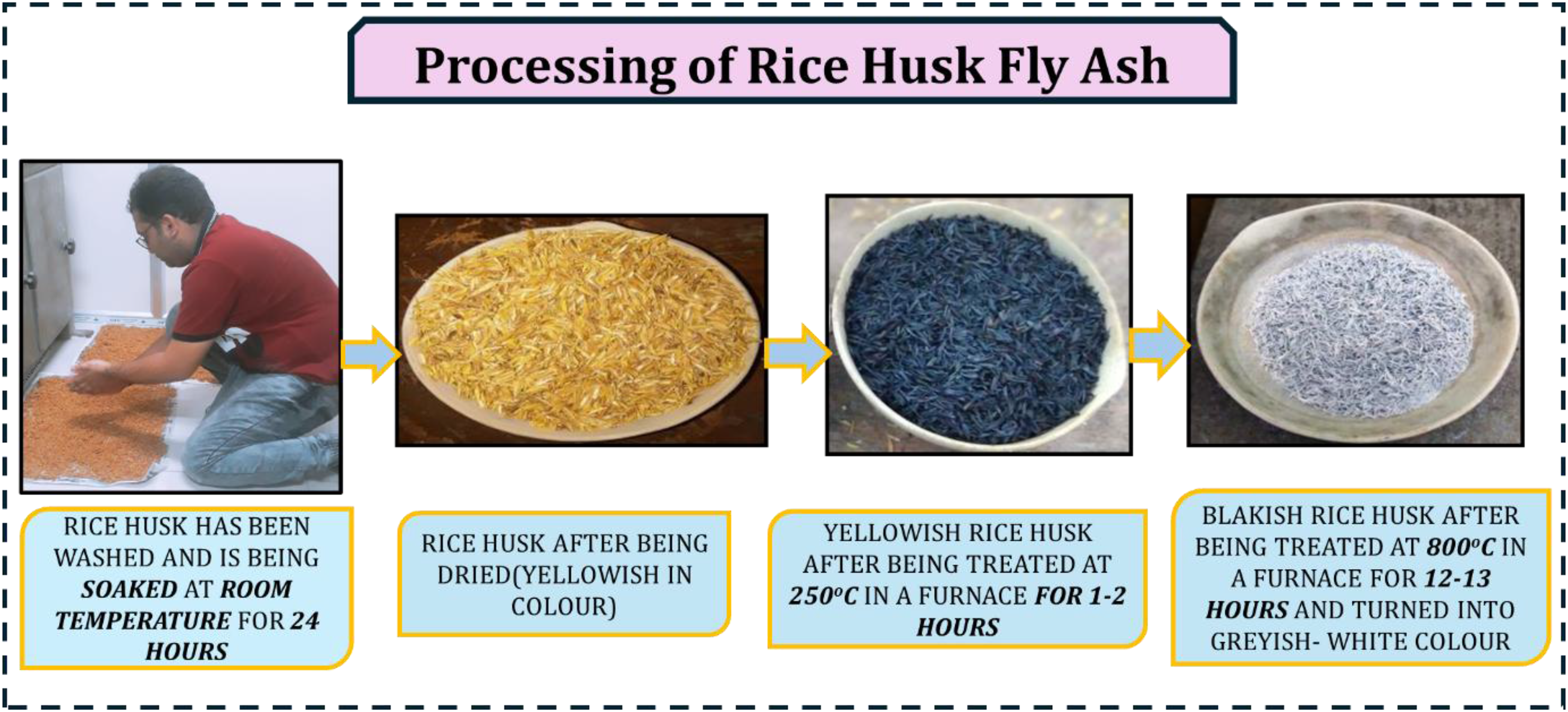
Synthesis of rice husk fly ash from paddy rice husk.
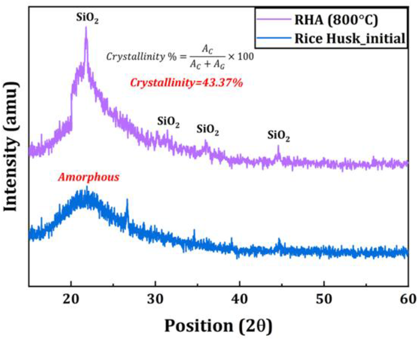
XRD patterns of raw rice husk and rice husk ash (RHA), showing the amorphous silica hump in rice husk and the crystalline silica peaks developed after calcination.
Fabrication method
Stir casting method of composite synthesis
Aluminum matrix composites (Al-MMCs) were synthesized using the stir casting technique, and the experimental setup is shown in Figure 3.16,17 Commercially pure aluminum (CP-Al) blocks were charged into a graphite crucible and melted in an electric resistance-pit furnace. To improve the wettability between the molten aluminum and the reinforcement phase, magnesium was added to the melt at a concentration of 1 wt.%. The addition was carried out by plunging small magnesium pieces wrapped in aluminum foil into the molten metal using a stainless-steel rod.
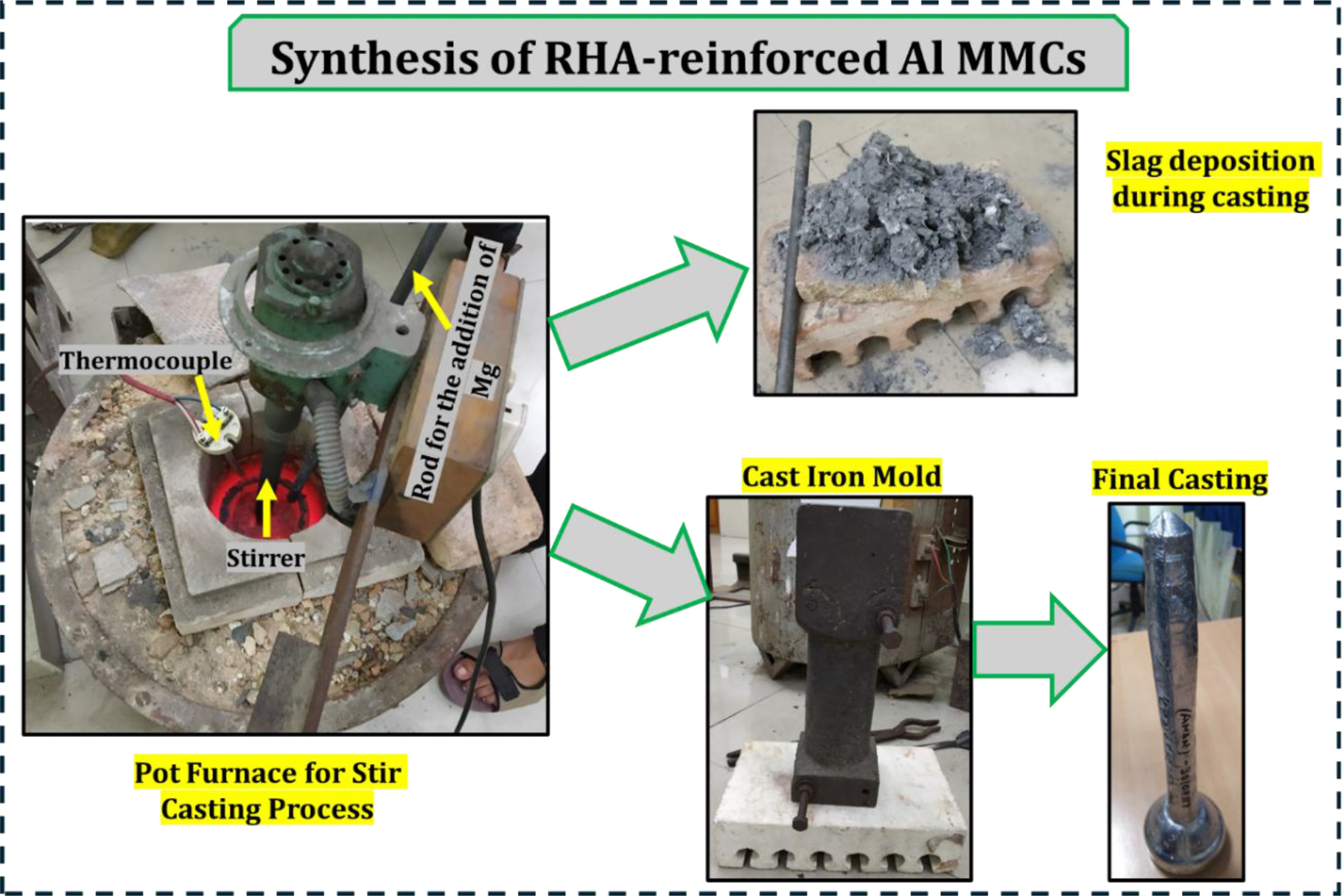
Processing of rice husk fly ash reinforced Al MMCs.
The reinforcement particles were subsequently introduced into the melt in the form of aluminum foil wrapped packets. These packets were attached to a stainless-steel rod using aluminum wires and immersed in the molten aluminum in a controlled manner. After the addition of the reinforcement, mechanical stirring was performed at rotational speeds in the range of 300–500 rpm for a duration of 30 min. Throughout the stirring process, the melt temperature was maintained at approximately 760 °C, which is well above the solidus (555 °C) and liquidus (650 °C) temperatures of CP-Al, ensuring complete melting and effective dispersion of the reinforcement particles. Degassing of the molten composite was carried out using 0.01 wt.% hexachloroethane to minimize dissolved gases and porosity. The treated melt was then poured into a cast iron mold conforming to standard BS1490 dimensions, as illustrated in Figure 3. The selected stirring speed and the placement of the stirrer at approximately 20% of the total melt height above the crucible bottom were based on literature reports to promote stable vortex formation, uniform particle distribution, and reduced gas entrapment. 21 Oxidation of the molten metal can occur at the melt surface, which leads to the formation of the Al2O3 oxide layer along with a small amount of MgO resulting from the addition of 1 wt.% Mg. To minimize the influence of oxidation products on the final composite, the slag layer formed on the melt surface was carefully removed after each addition step and immediately before pouring the melt into the mold as seen in Figure 3. This procedure ensured that the cast composites were produced from a relatively clean melt.
Mechanical properties testing
Tensile properties evaluation
The mechanical behavior of the Al MMCs and CP-Al was assessed through uniaxial tensile testing. Standard tensile specimens, as shown in Figure 4, were machined from the central region of the as-cast CP-Al MMC bars in accordance with ASTM E8 M specifications. Tensile tests were conducted on all samples using a universal testing machine (Instron 8516, UK) with a maximum load capacity of 100 kN. The machine operates using hydraulically generated load, controlled by a servo-feedback mechanism, and all tests were performed at a constant strain rate of 1 × 10⁻⁴ s−1. For each sample, 3 tensile specimens were subjected to testing to ensure repeatability. The reported tensile properties represent the average of the measured values, and the corresponding standard deviations were included to indicate data scatter and experimental reliability.
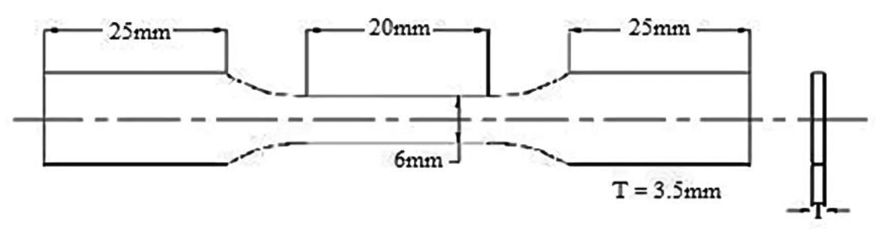
Specimen dimensions for tensile testing.
Micro hardness
To understand the type of strengthening mechanisms occurring in the Al MMCs, microhardness measurements were performed using a Vickers microhardness tester in accordance with ASTM E384 specifications. The indentations were done at regions encompassing both the RHA particles and the surrounding Al matrix to assess the local mechanical response at the reinforcement–matrix interface.
Dry-Sliding wear experiment
Dry-sliding wear behavior of CP-Al and the synthesized composites was evaluated using a pin-on-disk tribometer (Wear and Friction Monitor, TR-20LE, DUCOM, Bangalore, India) following ASTM standards. 22 Pin-shaped specimens having a length of 20 mm and a diameter of 6 mm were subjected to a wear test on rotating EN31 steel, having a hardness of 60 HRC (≈695 HV). All tests were performed at a constant rotational speed of 200 rpm under variable normal loads of 20, 40, and 60 N. The tests were conducted in ambient air with an average relative humidity of approximately 55%. The track diameter for the wear test was maintained at 100 mm, corresponding to a sliding velocity of 1.0 m·s−1. 23 Before testing, the pin surfaces were polished using 800-grit silicon carbide abrasive paper to obtain a consistent surface finish. Each wear test was carried out for 32 min, resulting in a total sliding distance of 2 km. The mass of each Al MMC sample was measured before and after the test using a high-precision analytical balance (CPA-225D, Sartorius, Germany), and the weight loss was used to calculate the specific wear rate, expressed in g m−2 m−1.
During the wear experiments, the cumulative wear depth (µm) and frictional force (N) were continuously monitored as functions of time. The coefficient of friction (µ) was determined from the recorded frictional force (Fᵣ) and the applied normal load (P) using the relation given in Equation (2).
The obtained data were further used to plot cumulative wear loss versus sliding distance and coefficient of friction versus sliding distance.
Characterization studies
Optical metallography
For metallographic examination, small specimens were machined from the central region of the Al MMC bars. The samples were prepared using standard metallographic procedures, followed by polishing and subsequent etching with 
XRD and SEM-EDS characterization
The specimens were characterized at room temperature by X-ray diffraction (XRD) using Cu-Kα radiation (λ = 0.15406 nm) at an operating voltage of 45 kV and a current of 40 mA. Microstructural and phase morphology analyses were carried out using a tungsten-based Scanning Electron Microscope (W-SEM, Carl Zeiss EVO 50) operated in backscattered electron (BSE) mode at an accelerating voltage of 20 kV.
For compositional analysis, Energy Dispersive Spectroscopy (EDS) was employed, with both area and point scans performed to identify elemental distributions. SEM-EDS analyses were conducted at different cross-sections of the specimens to assess phase composition and to verify the homogeneity of the reinforcement and matrix phases.
Results and discussion:
Microstructure of as-cast Cp-Al
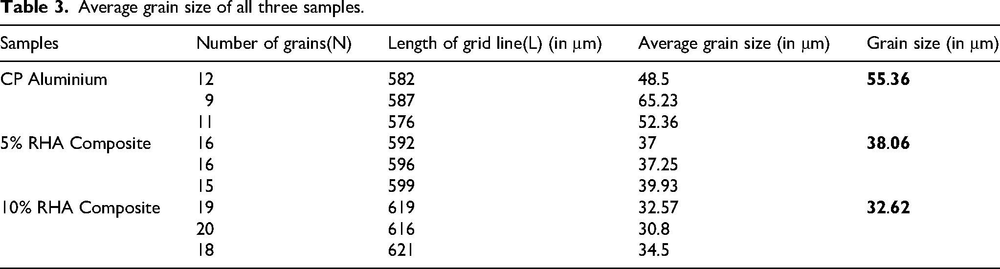
The optical micrograph of the as-cast CP-Al sample (Figure 5(a)) reveals a mixed grain morphology comprising primary columnar dendritic α-Al grains alongside equiaxed α-Al grains. The average grain size was measured to be approximately 55 µm, as summarized in Table 3. Higher-magnification observations using backscattered electron scanning electron microscopy show the presence of fine silicon-rich features distributed within the intergranular regions. These features are predominantly located at interdendritic zones and at triple junctions between equiaxed α-Al grains, as illustrated in Figure 5(b).
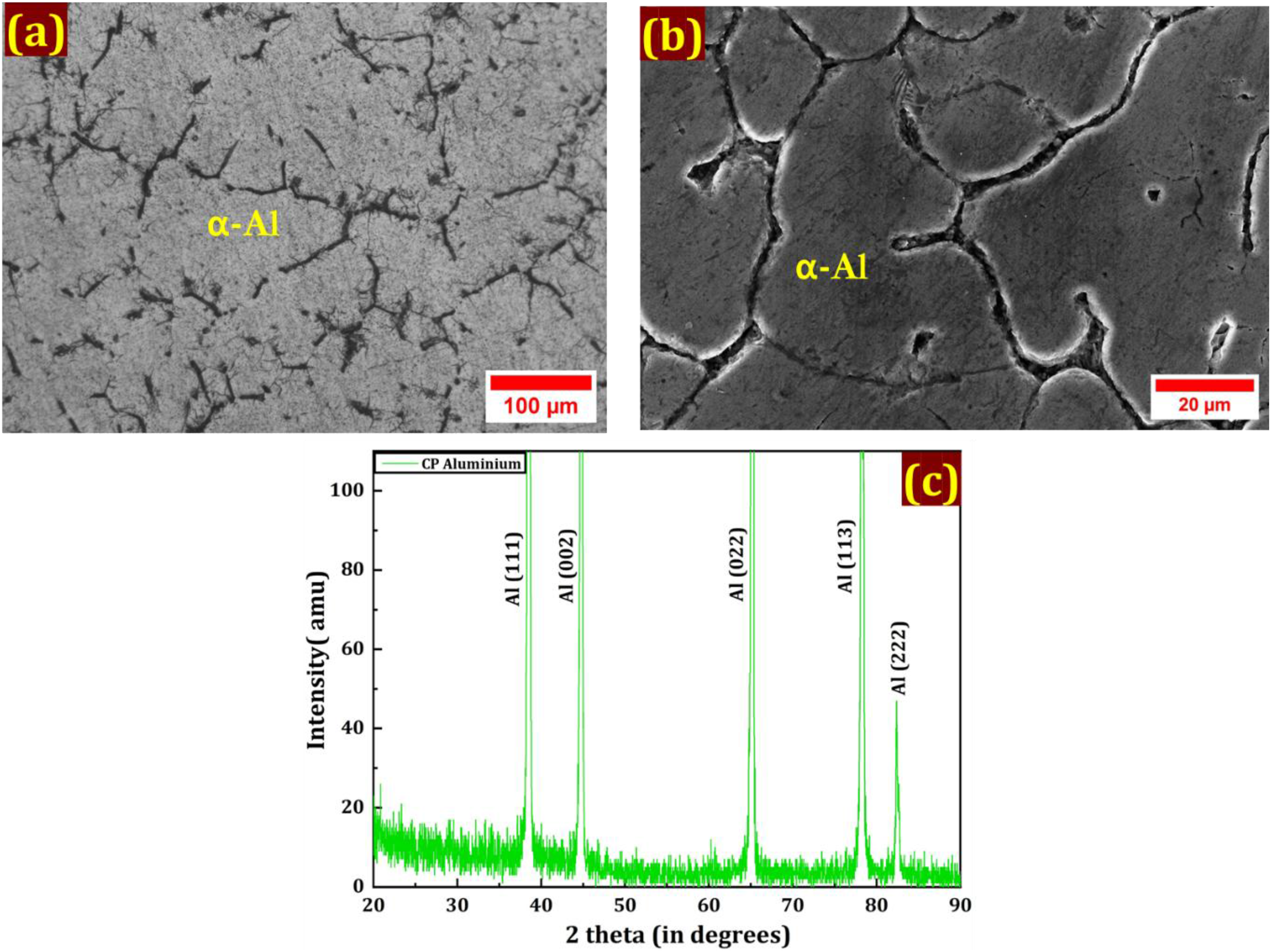
Microstructure of CP-Al (a) Optical image of CP-Al, (b) Backscattered micrograph of the CP-Al, and (c) XRD of the CP-Al.
Average grain size of all three samples.
The existence of equiaxed grain and columnar dendritic structures was observed during the solidification of small Al-Mg-Si alloy castings in metallic molds, where elevated cooling rates prevail. 25 During solidification, solute redistribution occurs at the advancing solid–liquid interface, resulting in the early-formed α-Al phase being comparatively solute-depleted, while the remaining liquid becomes progressively enriched in alloying elements, particularly silicon. The last portions of liquid solidify mainly within interdendritic regions, and grain boundary intersections exhibit higher silicon concentrations.
For the present hypereutectic Al–Si alloy system, solidification initiates with the formation of primary silicon particles. This is followed by the solidification of the residual liquid through a non-equilibrium, divorced eutectic mechanism. Under such conditions, eutectic silicon preferentially nucleates on pre-existing primary silicon particles and grows into rod-like morphologies, whereas the eutectic aluminum phase merges with the surrounding α-Al matrix. These microstructural features are corroborated by the X-ray diffraction pattern of CP-Al (Figure 5(c)), which is dominated by diffraction peaks corresponding to aluminum.
Microstructure of Cp-Al + 5% and 10% RHA composites
Figures 6(a)–(d) present the optical and scanning electron micrographs of CP-Al composites reinforced with 5 wt.% and 10 wt.% RHA. Both composites exhibit a predominantly fine equiaxed α-Al grain structure, indicating a pronounced modification of the solidification morphology compared to unreinforced CP-Al. The average grain size decreases from the value observed in the base alloy to approximately 38 µm for the CP-Al + 5% RHA composite and further to about 33 µm for the CP-Al + 10% RHA composite, demonstrating a progressive grain refinement effect with increasing RHA content. The formation of columnar dendritic grains is largely suppressed and confined to isolated regions.
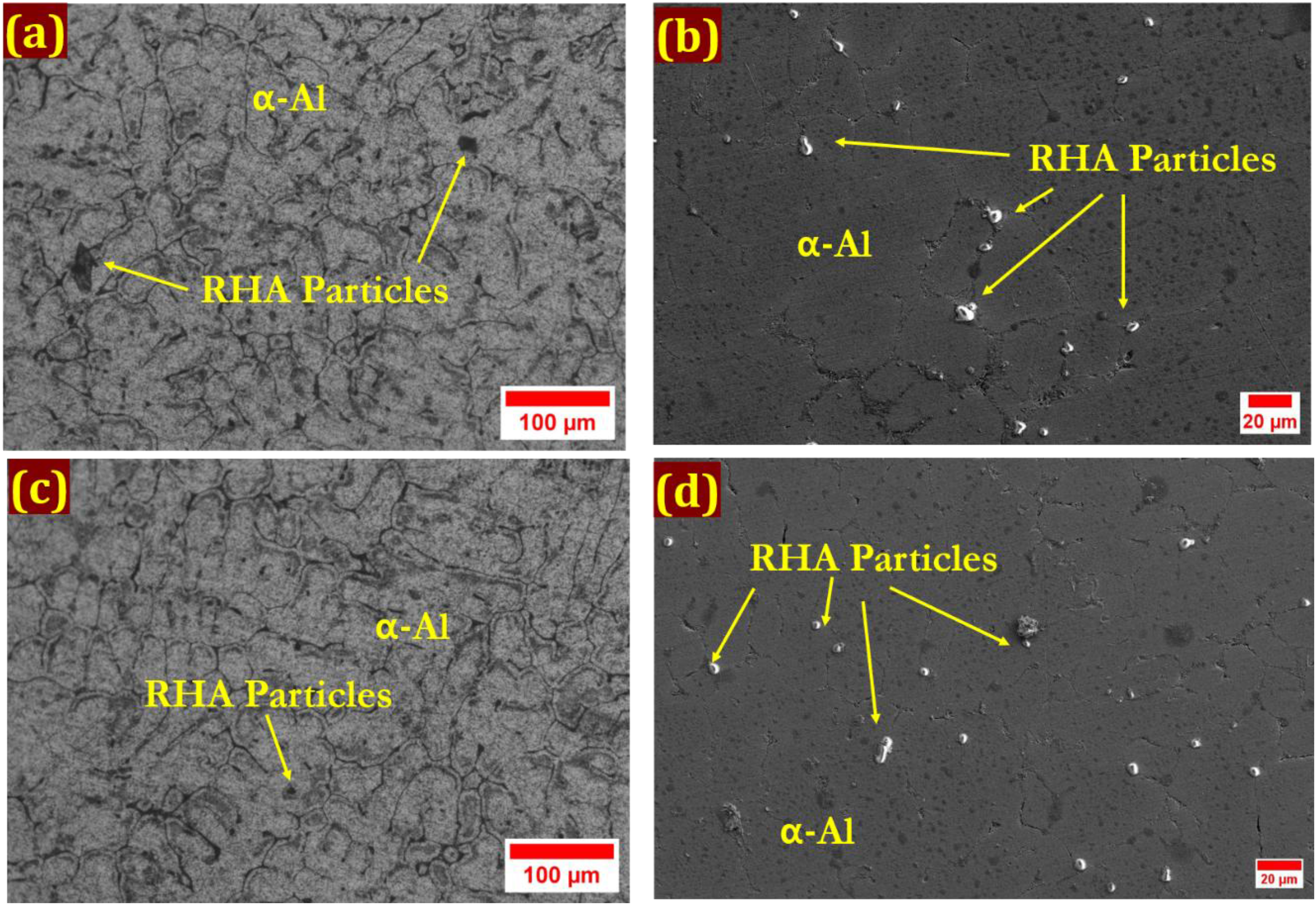
Optical and SEM micrographs of (a)&(b) 5% -CP Al MMC and (c)&(d)10% RHA-CP Al MMC.
The RHA particles are distributed throughout the matrix, occurring both as discrete particles and as limited clusters. A significant fraction of the particles is located at grain boundary triple junctions, as shown in Figures 6(b) and 6(d), indicating that the RHA particles act as potent heterogeneous nucleation sites during solidification. This particle-stimulated nucleation mechanism, combined with the physical restriction imposed by the particles on grain boundary migration, accounts for the observed reduction in grain size. The enhanced grain refinement at higher RHA content further supports this interpretation. In addition, particles are also observed along grain boundaries and within the α-Al grains (Figures 6(a) and 6(c)), suggesting effective incorporation of the reinforcement into the matrix during stir casting.
X-ray diffraction patterns of the composites (Figure 7) show diffraction peaks corresponding exclusively to aluminum and silica (SiO2), with the silica phase identified as cristobalite.26,27 No peaks corresponding to intermetallic compounds or reaction products are detected. This confirms that the RHA particles remain chemically and thermodynamically stable under the processing conditions employed and do not react with the CP-Al matrix. 28 The absence of interfacial reaction layers implies the formation of a clean matrix-reinforcement interface, which is critical for efficient load transfer and the activation of strengthening mechanisms, such as grain refinement and particle reinforcement. The preservation of interfacial integrity is therefore expected to contribute positively to the mechanical and tribological performance of the composites. 29
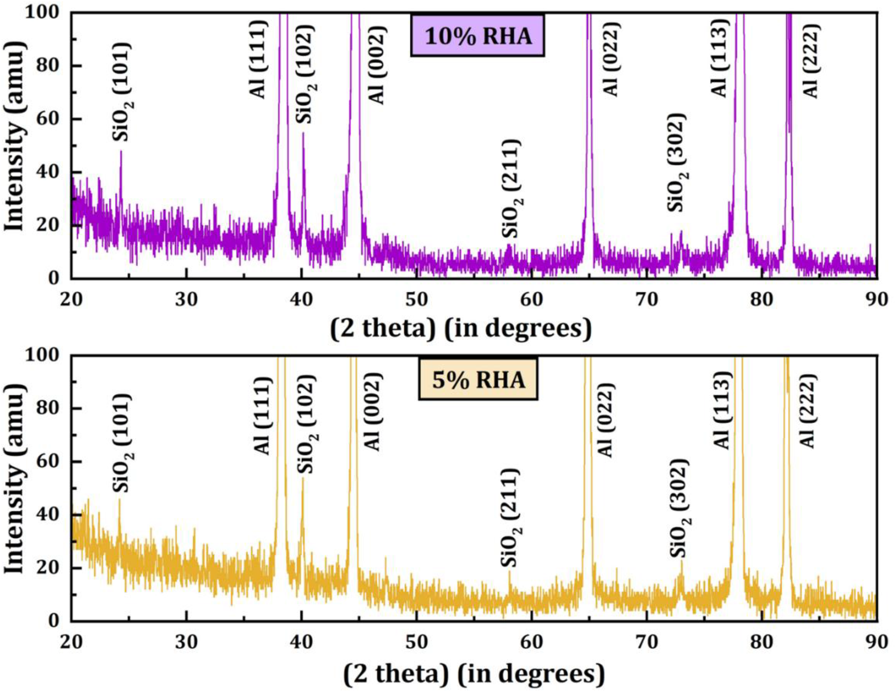
XRD of the 5% RHA CP Al MMC and 10% RHA CP Al MMC.
Mechanical properties
Comparison of tensile behavior between the Cp-Al and RHA-Al MMC sample
The tensile behavior of commercially pure aluminum (CP-Al) and rice husk ash (RHA) reinforced aluminum metal matrix composites (MMCs) was evaluated, with the results summarized in the provided Table 4 and shown in Figure 8 (a). The data indicate a substantial enhancement in mechanical properties due to the incorporation of RHA particles.
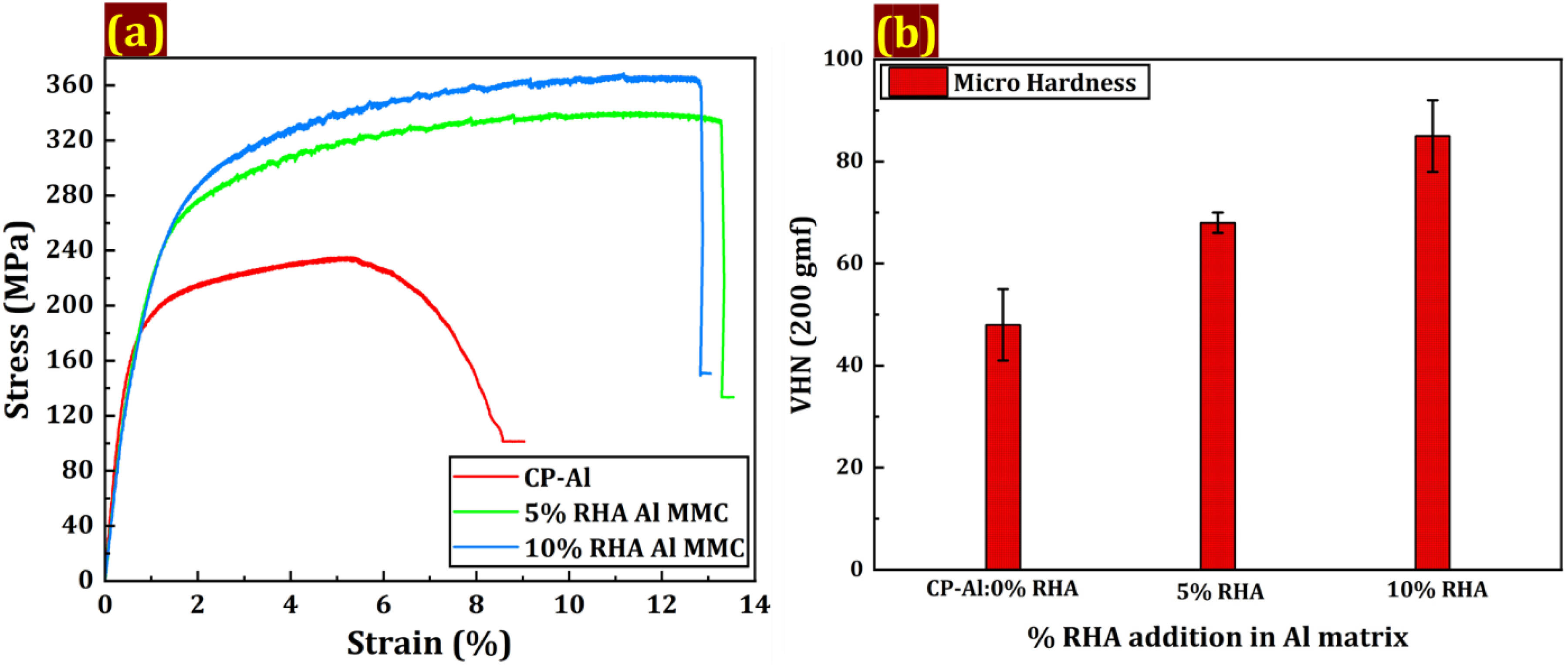
(a) Comparison of stress-strain plots of CP-Al, 5%RHA, and 10% RHA Al MMC samples, (b) Comparison of microhardness of CP-Al, 5%RHA, and 10% RHA Al MMC samples.
Mechanical properties of CP-Al, 5%RHA, and 10% RHA Al MMC samples.

The influence of RHA weight percentage on the hardness, ultimate tensile strength (UTS), and Young's modulus is clearly demonstrated. The composite reinforced with 10 wt% RHA exhibited the most significant improvement, showing a 77% increase in Vickers hardness (VHN) and a 61.25% increase in UTS compared to unreinforced CP-Al. A notable improvement was also observed for the 5 wt% RHA composites, which displayed a 41% increase in hardness and a 16% increase in UTS (Figure 8 (b)). These findings are consistent with similar research in the field 30 and confirm that RHA particles act as an effective strengthening agent in the aluminum matrix.
To understand the type of strengthening mechanisms in the Al MMCs, various factors can be attributed to them. The difference in the coefficients of thermal expansion (CTE) between the Al matrix and the SiO2 based RHA particles generates residual stresses and creates the strain fields around these RHA particles during the solidification process. The strain fields act as a barrier to the dislocation movement, causing the stress to increase for plastic deformation. As discussed in the previous sections, the addition of RHA particles leads to grain refinement in the Al matrix. According to the established Hall-Petch relation, the smaller the grain size, the greater the yield strength, and because of the grain refinement, it will lead to the generation of grain boundaries, which will ultimately impede the dislocation movement and thus will increase the overall strength of the material. The well-bonded interface between the matrix and reinforcement ensures effective load transfer from the softer Al matrix to the harder, stronger RHA particles. Also, the uniform dispersion of RHA particles throughout the matrix contributes to Orowan strengthening. 31 This mechanism involves dislocations bowing around and bypassing the non-shearable particles, which also increases the stress required for continued deformation. The combined effect of these mechanisms, CTE mismatch, grain refinement, load transfer, and Orowan strengthening, results in the increase of hardness and ultimate tensile strength in the RHA-Al MMCs.
Wear behaviour:
Wear behaviour of 5% rice husk fly ash (RHA) based aluminium composites
The wear experiment results for the 5% RHA-based Al MMC are illustrated in Figures 9 (a) and (b). The cumulative wear versus sliding distance plots at different loads show a linear relationship. As the load increases from 20 N to 60 N, the slope of the plot also increases. Consistent with this, the coefficient of friction (COF) values at all loads remain relatively steady with only minor fluctuations, as shown in the figure. The plot has been divided into two different regions to properly understand the wear mechanisms occurring during the whole sliding distance. The first region, up to the 500 m region indicated by point P, suggests that the initial period for the wear to develop in this region is particularly slow. The shallow slope of the curve evidences this region. The region will have only minor modifications, likely due to the presence of RHA particles on the pin surface, which causes minimal plastic deformation at the surface of the pin due to the strain hardening effects, which will be explained in the later sections. During this initial period (0–500 m), the cumulative wear under the three different load conditions increases steadily, with the wear rate remaining almost identical for different loads. The initial uniformity, as indicated by the proximity of the curves, suggests that during the early stages of sliding, the wear mechanism is similar across all conditions.
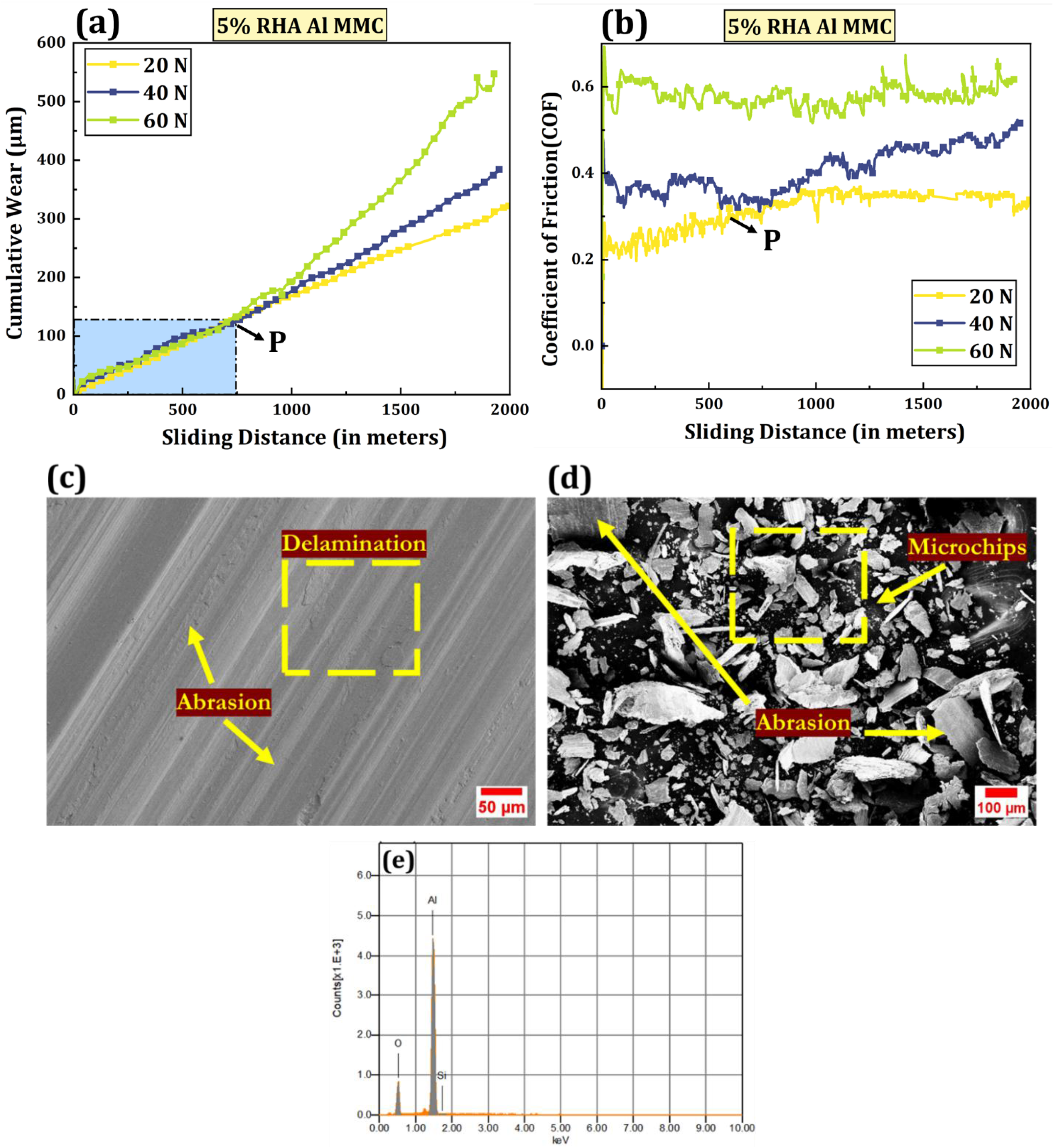
Wear experiment results for 5% RHA CP-Al MMC (a) Cumulative-wear versus sliding distance and (b) COF versus sliding distance, SEM micrographs of worn surface and wear debris of 5% RHA Al MMCs at 20 N load (c) Worn surface, (d) Wear debris, and (e) EDS spectrum of the worn surface.
During sliding wear, the material response is governed by the competition between wear-mitigating and wear-promoting mechanisms. Wear resistance arises primarily from surface strain hardening and the formation of a compact, adherent oxide layer on the worn surface. This oxide film acts as a protective and lubricating layer by reducing direct metal-to-metal contact between the pin and the counter face, thereby limiting material loss. In contrast, wear progression is driven by mechanisms such as micro-cutting abrasion, ploughing, adhesion, delamination, and the formation of non-adherent oxide debris.32,33 Up to a critical point (P) for all applied loads, a dynamic equilibrium exists between the wear-resisting and wear-driving mechanisms, resulting in a nearly linear increase in cumulative wear with sliding distance. Beyond this point, the protective mechanisms become ineffective, and the wear-driving processes dominate, leading to a rapid and accelerated increase in cumulative wear.
At 20 N load, 5% RHA Al MMC exhibits lower cumulative wear than other applied loads, suggesting the dominance of mild wear mechanisms throughout the sliding distance of 2000 m. Figure 9 (c) shows mainly abrasion marks on the worn surface; several adhesion regions along with cracks are also present. In addition to this, there is also an oxide formation, as can be seen by the EDS result in Figure 9 (e) on the surface of the pin during the sliding process because of the heat generation during friction. So, as explained earlier initial period, i.e., up to a sliding distance of 500 m, there is a balance between the wear-resisting and wear-causing mechanisms, so there exists a linear increase in wear, and similar trends also occurred for the coefficient of friction (COF) values as the COF is fluctuating between 0.2 and 0.3 at the initial period. Figure 9 (d) shows the SEM micrograph of the wear debris, which shows the microchips and the thin sheets that contain abrasion marks. This suggests that abrasion occurred much earlier than delamination. Thus, it can be stated that after point P (i.e., after 500 m), wear is predominantly caused by adhesion, micro-cutting-abrasion, and delamination for a 20 N load.
For a 40 N applied load, similar to a 20 N load, the 5% RHA Al MMC exhibits continuous wear loss, whereas the COF at the initial period upto point P decreases initially, but after the transition point P, it starts to increase again. However, the wear rate is higher compared to 20 N. Figure 10 (a) shows the SEM micrograph of the worn surface of the 40 N load pin. The abrasion marks are seen to be slightly wider and deeper as compared with the 20 N load, as shown in Figure 10 (a). Thus, this accounts for the reason for the higher slope of the cumulative wear curve for 40 N as compared to 20 N load. Like in the 20 N load, there will be oxide formation in the 40 N load because of the usual reason that higher load will cause more heating between the pin and the steel disc of the Pin-on-Disc setup to cause oxidation of the worn surface and thus the oxidation will be more prominent in the case of 40 N load this was verified by the SEM-EDS of the worn surface of the 40 N load as can be seen in Figure 10 (e) it shows higher O elemental content than 20 N load. The oxidation of the worn surface will provide lubrication to the pin and will resist wear. Thus, the 40 N applied load experiment is dominated by abrasion, having deeper marks, which causes delamination of the surface into the thin sheets, as can be seen in the SEM micrograph of the wear debris obtained after the experiment (Figure 10 (b) & (c)).
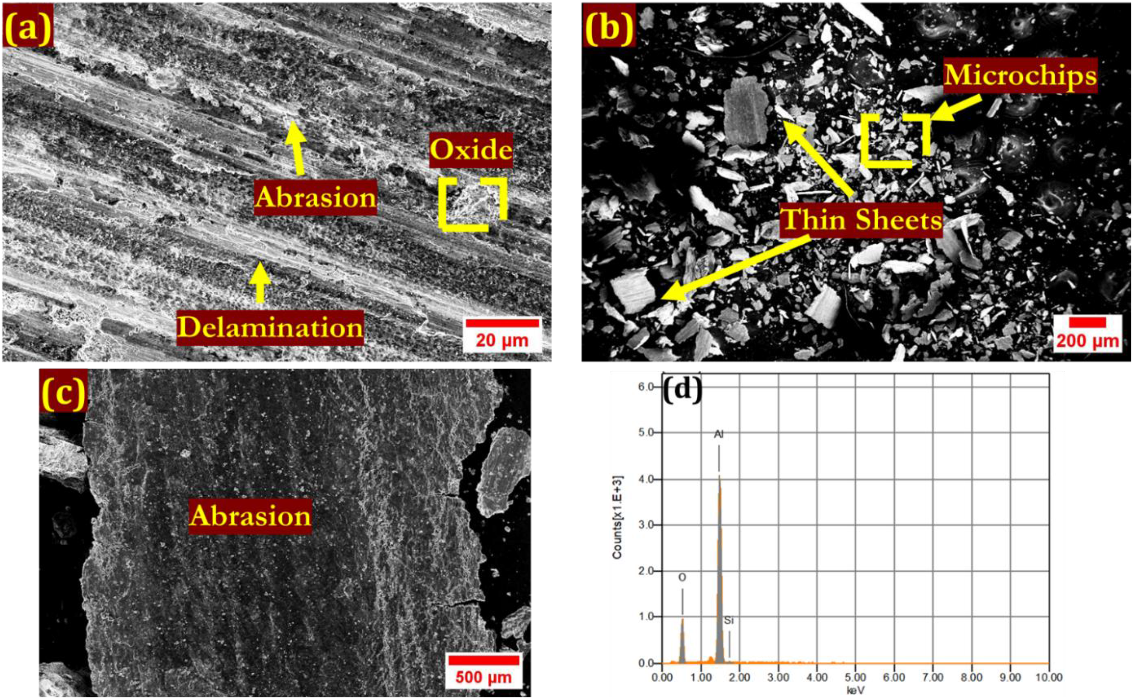
SEM-micrographs of worn surface and wear debris of 5% RHA Al-MMCs at 40 N(a) Worn surface, (b) Wear debris, (c) SEM micrograph of thin sheet present in the wear debris depicting the abrasion marks, and (d) EDS analysis of the worn surface.
The 60 N applied load exhibits a similar trend upto the point P, and cumulative wear follows the linear trend. Thus, up to point P wear rate is almost constant, but after point P wear rate increases drastically, indicating that the material undergoes a severe wear mechanism beyond this point. It suggests that the material is experiencing severe degradation, which will cause material removal.
Wear behaviour of 10% rice husk fly ash (RHA) based aluminium composites
Figure 11 (a) represents plots representing cumulative wear with respect to the sliding distance for varying loads from 20 N to 60 N, while Figure 11-(b) represents the corresponding COF plot with respect to the sliding distance. The plot represents the increase in the cumulative wear with the increase in load from 20 N to 60 N, while the COF representing the effect of load shows major fluctuation with the sliding distance. Figure 12 (a)-(b) depicts the worn surface and wear debris images, along with Figure 12 (c)-(e), which represents the SEM-EDS results of the wear debris for the 20 N load. The worn surface micrograph of the 20 N load shows the presence of delamination and abrasion marks, along with some adhesion regions that are also present. During the initial period that is upto point P (upto 300 m), wear occurs linearly. After which, ongoing resistance to further wear is seen in Figure 11-(a), which depicts that the value of cumulative wear goes down and attains a constant value for the remaining sliding distance, and corresponds to the fact that the COF value also decreases below 0.1 and remains steady after that. The initial part of the wear that is upto point P is attributed to the abrasive and adhesive wear. The latter part, that is, after point P, is because of the wear debris deposited, which mainly contains RHA particles, as can be seen in the SEM-EDS mapping results (Figure 12 (e)). These particles or chips resist abrasive wear, resulting in a low value of cumulative wear. The EDS results also show the oxide formation in the sample, which was due to the heating effect during the wear experiment.
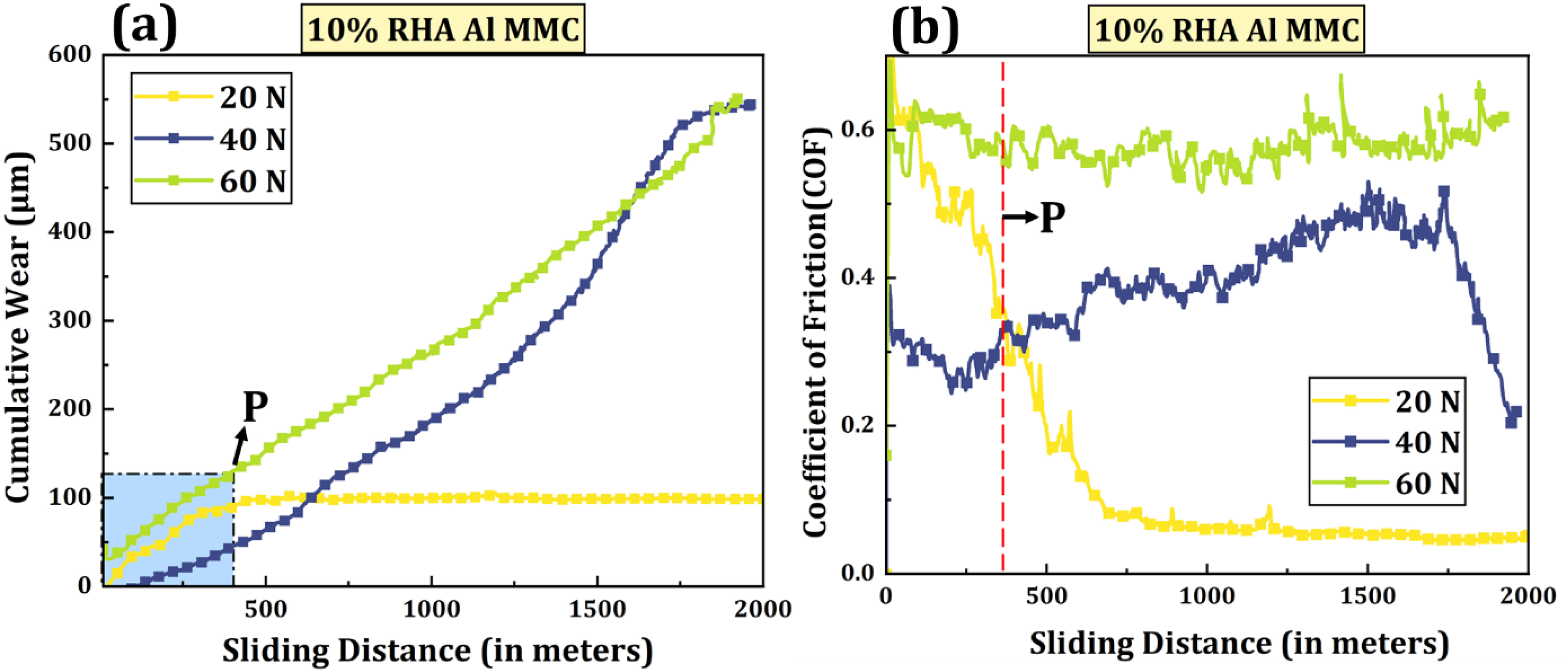
Wear experiment results for 10% RHA CP-Al MMC (a) Cumulative wear versus sliding distance and (b) COF versus sliding distance.
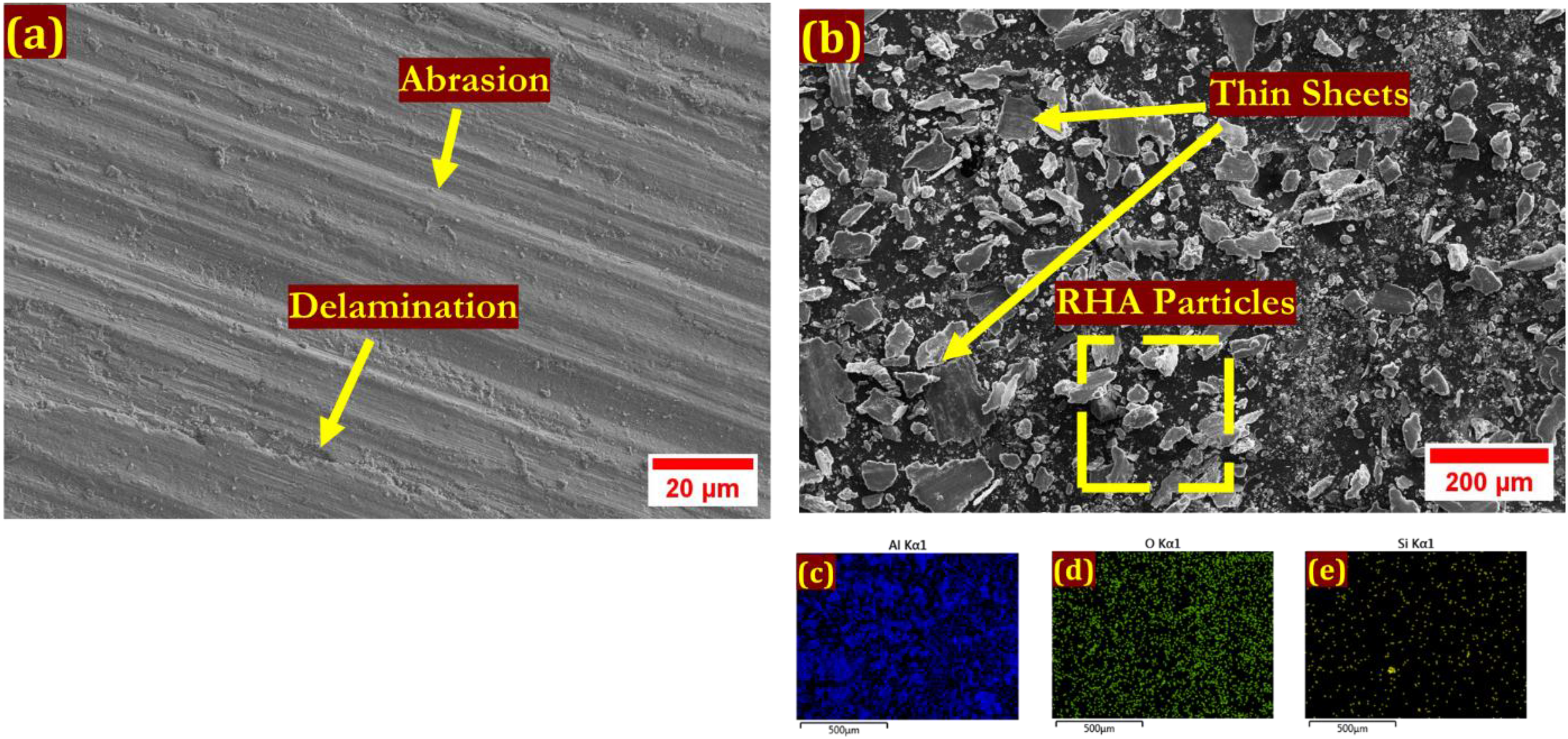
SEM images of worn surface and wear debris of 10% RHA Al MMCs at 20 N (a) Worn surface, (b) Wear debris, SEM-EDS mapping of the wear debris showing presence of (c) Al, (d) O, and (e) Si.
Up to a sliding distance of 1500 m, the cumulative wear loss at 40 N load consistently varies linearly but at a decreasing rate. After that, the value of the cumulative wear increases at an increasing rate. The COF initially maintains a somewhat constant value with minor fluctuation, but as the sliding distance increases, the value of COF also increases upto the value of 0.5 with the increase in cumulative wear, after which it attains a constant value. Figures 13 (a) and (b) show that although the cumulative wear value is higher than the 20 N load, the abrasion marks are deeper and wider. The SEM-EDS results of the wear debris show that the worn surface generally shows abrasion marks with oxidation on the sample. Thus, the possible wear mechanism is mainly due to the micro-cutting abrasion and adhesion, while a certain amount of delamination has also appeared in the worn sample.
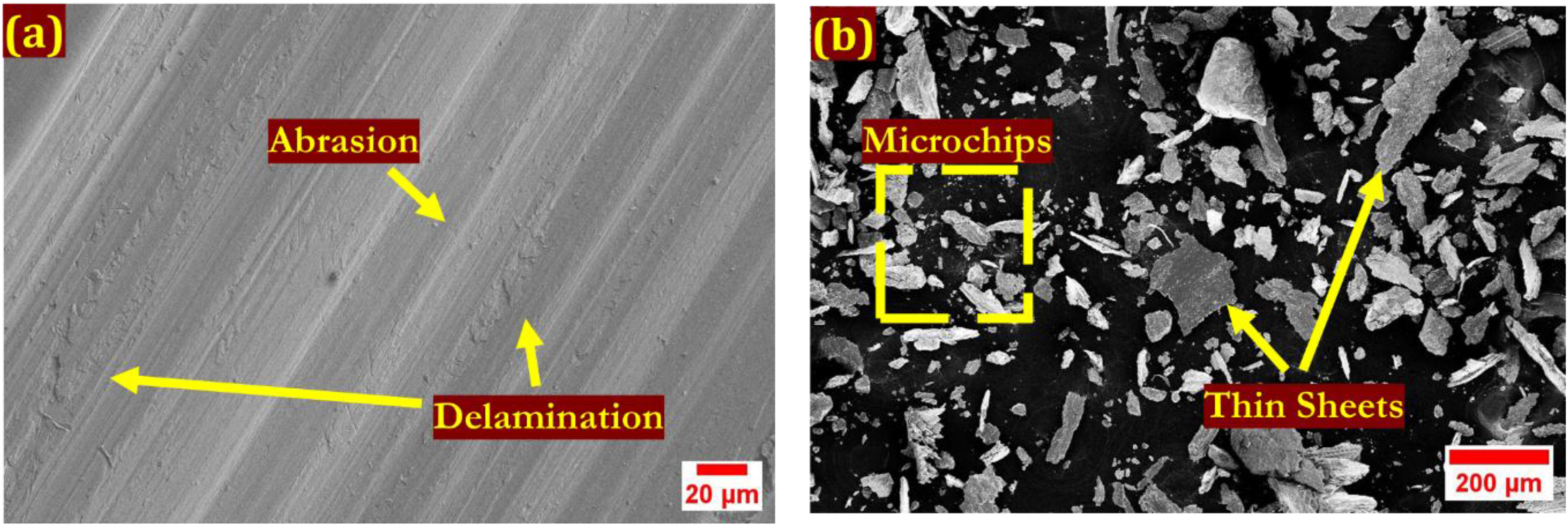
SEM images of worn surface and wear debris of 10% RHA Al MMCs at 40 N (a) Worn surface, (b) Wear debris.
For the 60 N load, the cumulative wear increases linearly as for the other loads, but during the whole sliding distance, and the slope continuously increases, corresponding to it, the COF is showing a higher but constant value with minor fluctuations. The SEM image (Figure 14 (a)) of the worn surface depicts the presence of RHA particles on the surface, which are helping in resisting the abrasion wear, causing less wear than the 5% RHA Al MMC. The SEM-EDS (Figure 14 (b)-(e)) of the wear debris of the sample shows the presence of thin sheets in place of microchips, suggesting that the wear mechanism for the 60 N load is dominated by abrasion and delamination (Figure 14 (f)). Also, the EDS results show the presence of oxide formation throughout the worn surface.
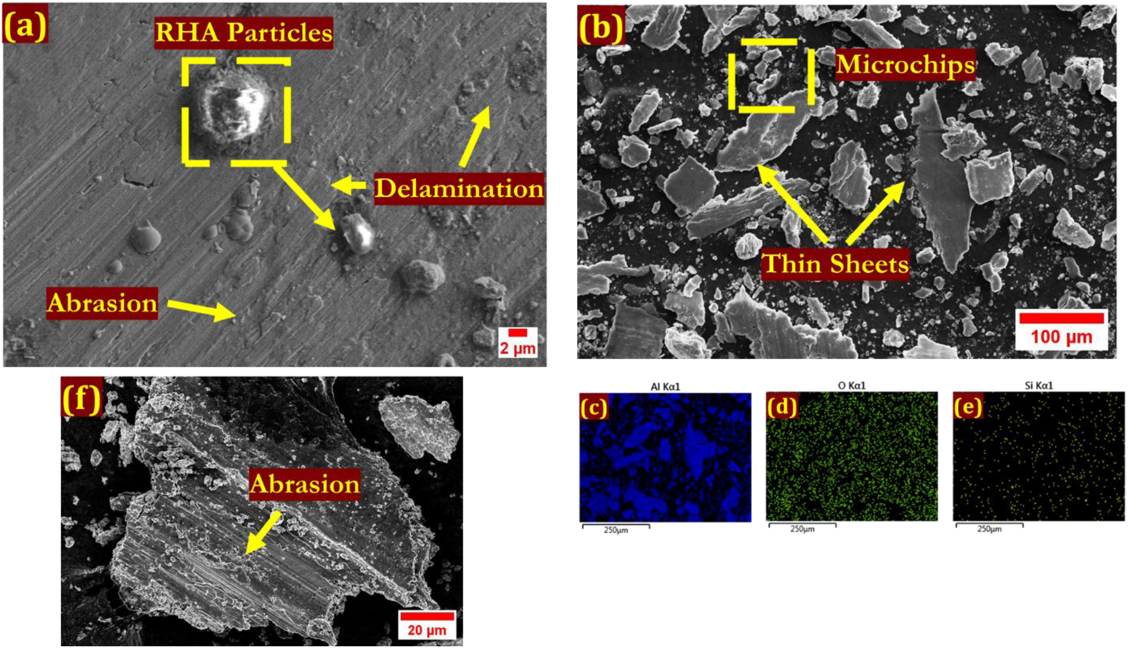
SEM micrographs of worn surface and wear debris of 10% RHA Al MMCs at 60 N(a) Worn surface, (b) Wear debris, SEM-EDS mapping of the wear debris showing presence of (c) Al, (d) O, and (e) Si, (f) SEM micrograph of the thin sheets present in the wear debris showing the deep abrasion marks.
Effect of RHA particle addition on the wear rate
Figure 15 depicts the wear rate plot for all three samples, i.e., CP-Al, 5% RHA Al MMC, and 10% RHA Al MMC with varying loads. The wear rate of the samples is calculated with the help of the weight loss occurring during the Pin-on-Disc experiments at various loads by the help of Equation 4.
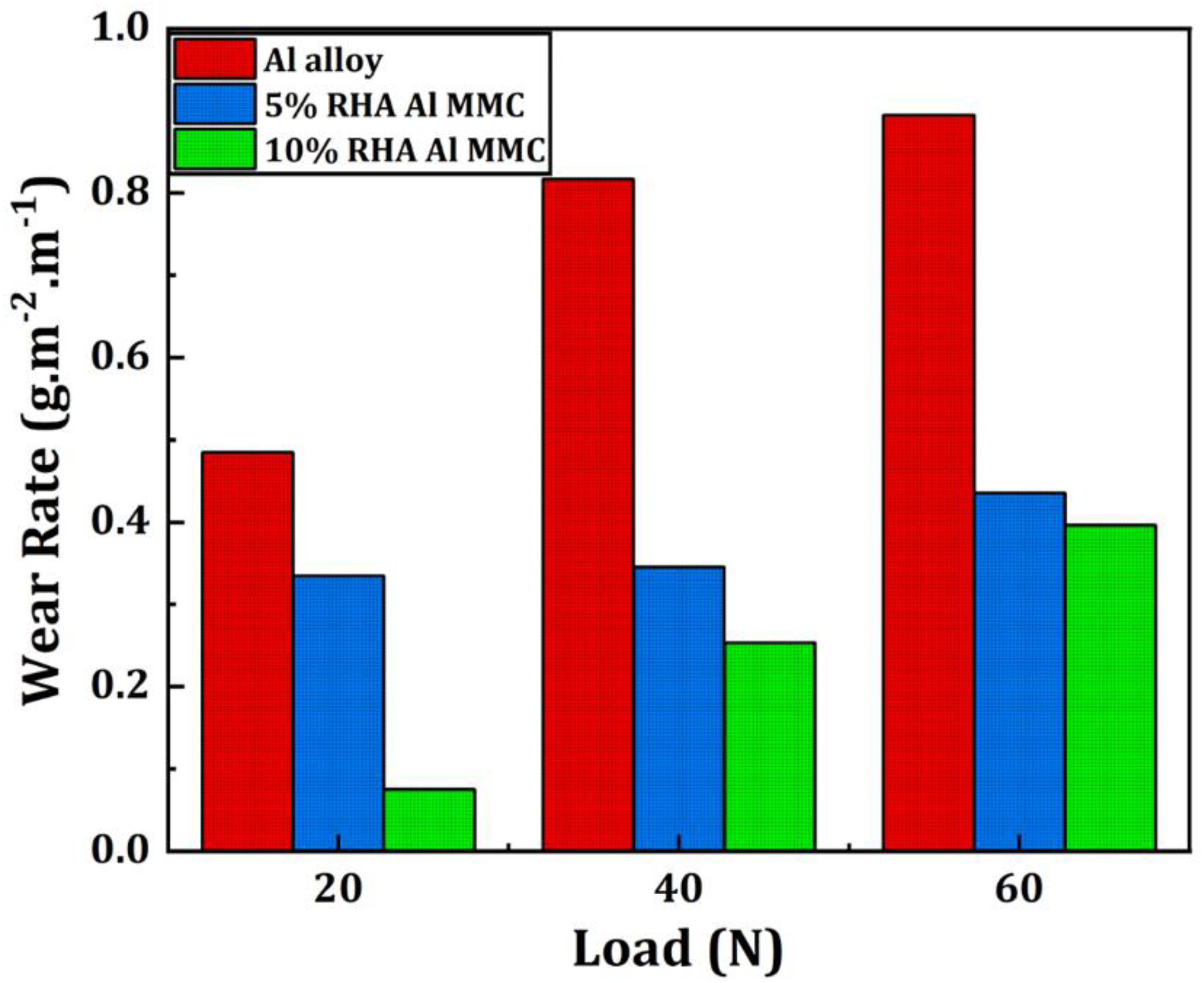
Comparison of wear rate versus varying load among CP-Al, 5% RHA Al MMC, and 10% RHA Al MMC.
The wear rate increases with applied load for all samples. At a normal load of 20 N, the 5% and 10% RHA-reinforced Al MMCs show lower wear rates compared to CP-Al, confirming their superior wear resistance. This behavior is attributed to the presence of RHA particles, which are uniformly dispersed along grain boundaries and exhibit strong interfacial bonding with the Al matrix, as evidenced in the microstructures (Figure). Such bonding minimizes particle pull-out during sliding and enhances wear resistance.
With increasing RHA content from 5 to 10 wt.%, the wear rate further decreases due to the more homogeneous particle distribution, particularly along grain boundaries and triple junctions. This promotes grain refinement and strengthens the matrix, thereby improving hardness and tensile strength, as discussed earlier. At higher loads (above 40 N), both CP-Al and RHA-reinforced MMCs exhibit a reduced rate of increase in wear. This effect is linked to the formation of adherent oxide layers generated by frictional heating at 60 N, which act as a solid lubricant and reduce material loss. 34 Nonetheless, the positive influence of RHA addition is restricted by the dissolution limit of CP-Al; beyond this limit, excessive reinforcement can lead to deterioration of mechanical and tribological properties.16,17
Conclusions
The following conclusions can be drawn from the investigation on the microstructure, mechanical, and tribological properties of rice husk ash (RHA) reinforced commercially pure aluminum (CP-Al) composites:
The microstructure of as-cast CP-Al is greatly refined by the addition of RHA particles; the average grain size decreases from 55 µm to 38 µm and 33 µm for the 5 wt% and 10 wt% RHA composites, respectively. As strong nucleation sites, the RHA particles suppress the columnar dendritic growth seen in the unreinforced alloy and encourage a primarily equiaxed grain morphology. The mechanical properties are significantly improved by the RHA reinforcement; compared to unreinforced CP-Al, the 10% RHA composite shows a 77% increase in hardness and a 61.25% increase in ultimate tensile strength. The synergistic effect of several strengthening mechanisms, such as Orowan strengthening, strain fields produced by the coefficient of thermal expansion (CTE) mismatch, load transfer from the matrix to the hard ceramic particles, and grain refinement (Hall-Petch effect), is responsible for this improvement. XRD analysis confirms the presence of only Al and cristobalite SiO2 phases, indicating that the RHA particles remain thermodynamically stable during processing without forming deleterious intermetallic compounds. This results in a clean and well-bonded interface, which is crucial for effective load transfer and the consequent improvement in mechanical strength. The incorporation of RHA particles markedly improves the wear resistance of the aluminum matrix. Both 5% and 10% RHA composites demonstrate a lower wear rate than CP-Al across all tested loads (20–60 N). The superior performance is due to the hard RHA particles imparting load-bearing capacity, hindering plastic deformation, and reducing abrasion through their uniform distribution and strong interfacial bonding, which minimizes particle pull-out. The wear behavior is governed by a balance between wear-resisting mechanisms (strain hardening, formation of lubricating oxide layers) and wear-causing mechanisms (abrasion, adhesion, delamination). At higher loads (≥40 N), the formation of a tribo-oxide layer on the composite surfaces acts as a solid lubricant, mitigating the wear rate. The 10% RHA composite shows the most stable performance, with evidence of wear debris containing RHA particles themselves contributing to a reduction in the coefficient of friction and wear rate at higher sliding distances.
Footnotes
Acknowledgements
The authors gratefully acknowledge the Department of Metallurgical and Materials Engineering (MME), National Institute of Technology (NIT) Durgapur, and the Advanced Centre for Materials Science (ACMS), Indian Institute of Technology (IIT) Kanpur, for providing the facilities and infrastructure necessary to carry out this research. The authors also sincerely thank Mr Anil Kumar of the Indian Institute of Technology (IIT) Roorkee for providing the rice husk samples used in this study.

Author contribution(s)
Funding
The authors received no financial support for the research, authorship, and/or publication of this article.
Declaration of conflicting interests
The authors declared no potential conflicts of interest with respect to the research, authorship, and/or publication of this article.