
Abstract
This study compares the mechanical, tribological, and corrosion characteristics of four different substrates: untreated (UNT), untreated substrate then coating (UNTC), LSP-treated (LSPT), and LSP-treated then coating (LSPTC). This study explains how the dual surface treatment LSP and W_HVOF based molybdenum coating on the mechanical properties and corrosion resistance of AA5083 aluminum alloy. Nanoindentation tests revealed significant improvements in hardness and Young's modulus for LSPTC specimens. Surface roughness analysis showed that LSPTC specimen increased roughness, potentially to enhancing coating bonding. Scratch and wear tests demonstrated superior wear resistance for LSPTC specimens due to their higher hardness and reduced friction. Contact angle measurements indicated that LSPTC specimen made the surfaces more hydrophobic. Electrochemical corrosion analysis revealed that LSPTC specimens exhibited the lowest corrosion rates, outperforming untreated and LSPT specimens. FESEM and XRD analyses confirmed the positive effects of LSPTC specimen on microstructure and residual stress, contributing to the improved mechanical properties and corrosion resistance.
Keywords
Introduction
Aluminum alloys, particularly the 5xxx series, have garnered significant interes-t in engineering applications due to their high strength-to-weight ratio, corrosion resistance, and good formability. These properties make them highly suitable for critical engine components, aerospace structures, marine applications, and pipelines for gas fuel transportation.1,2 However, despite their advantages, 5xxx aluminum alloys are susceptible to hydrogen embrittlement, corrosion, and wear, especially in harsh environments such as marine and high-pressure systems. 3 To enhance the performance of aluminum alloys in such conditions, surface treatments like LSP and HVOF coating have been explored extensively in recent years.
The 5083 series aluminum alloys, which are primarily alloyed with magnesium, exhibit excellent corrosion resistance and moderate strength, making them a popular choice for marine and automotive applications. The presence of magnesium enhances the alloy's resistance to corrosion in chloride environments, but these alloys can suffer from localized corrosion and hydrogen embrittlement, particularly when exposed to mechanical stresses. Hence, addressing these vulnerabilities has been a focal point of research in enhancing the life cycle of components made from these alloys.4,5
One of the most effective surface treatment techniques for enhancing the mechanical properties of aluminum alloys is LSP. LSP is a mechanical surface treatment that improves fatigue life, hardness, and resistance to stress corrosion cracking. 6 By applying specific-intensity laser pulses, LSP induces deep compressive residual stresses on the surface of the material, improving its resistance to crack initiation and propagation. 7 For engine components, where fatigue and wear resistance are critical, LSP has been shown to significantly improve performance and longevity. 8 Studies have demonstrated that LSP-treated aluminum alloys exhibit improved mechanical properties and greater resistance to hydrogen embrittlement, which is particularly beneficial in hydrogen-rich environments such as fuel transport pipelines.9,10
Another promising surface treatment is HVOF coating, which involves spraying molten or semi-molten particles at high velocities onto the substrate, forming a dense and hard coating. Molybdenum-based HVOF coatings on aluminum alloys have been extensively studied due to their excellent wear resistance, corrosion protection, and ability to function in high-temperature environments. 11 When applied to 5-series aluminum alloys, HVOF coatings act as a protective barrier against mechanical wear, corrosion, and hydrogen ingress, thus enhancing the alloy's resistance to hydrogen embrittlement. HVOF coatings have proven particularly useful in applications such as gas pipelines and marine environments, where the combination of corrosion and mechanical loading can lead to rapid degradation of uncoated components. 12
Hydrogen embrittlement is a major concern in gas fuel transportation pipelines and marine applications, where exposure to hydrogen can cause severe material degradation, leading to premature failure. The combined LSP and HVOF treatment effectively mitigates hydrogen embrittlement by preventing hydrogen ingress into the substrate and strengthening the material's surface. 13 Recent studies have demonstrated that this combined approach significantly improves the durability and corrosion resistance of 5-series aluminum alloys, particularly in aggressive environments. In the context of engine components, where high performance under extreme mechanical and thermal conditions is required, the combination of LSP and HVOF treatment has emerged as a highly effective solution. This dual treatment enhances fatigue resistance, reduces the risk of stress corrosion cracking, and improves overall wear resistance. In addition, the molybdenum-based HVOF coating offers excellent protection in high-temperature applications, such as those found in internal combustion engines. 13 In marine applications, where aluminum alloys are exposed to seawater and mechanical loading, the combination of LSP and HVOF coating provides critical improvements in corrosion resistance and mechanical durability. The treatments help to reduce the material's susceptibility to pitting and crevice corrosion, which are common issues in marine environments. 14 For gas fuel transportation pipelines, where hydrogen embrittlement is a significant concern, the combined LSP and HVOF treatment has shown great promise. By creating a protective surface layer and inducing compressive stresses, these treatments enhance the material's resistance to hydrogen-related degradation, ensuring the reliability and safety of pipelines.15,16
In this paper, the combination of LSP and HVOF coating presents a synergistic approach to surface treatment, offering enhanced mechanical properties and superior resistance to both wear and hydrogen embrittlement. By applying LSP first, deep compressive residual stresses are introduced, which improve fatigue resistance and inhibit crack growth. Following this, the HVOF coating provides a robust barrier against corrosion and mechanical wear. This combined treatment has been shown to significantly improve the performance of aluminum alloys in high-stress environments, making it a promising technique for extending the life of engine components, pipelines, and marine structures.
Materials and methods
Materials
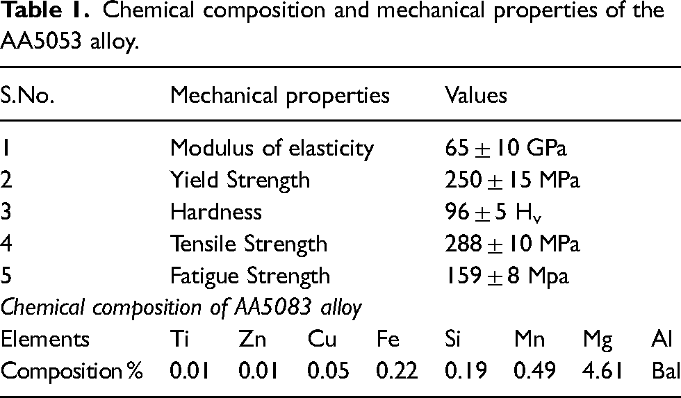
The AA5053 non-heat-treatable aluminium alloy of dimensions 150 × 50 × 6 mm3 was procured from PMC metals. Using wire EDM, the cut section (10 × 10 × 6 mm3) was subjected to prior mounting, polishing (SiC paper 200–1500), cleaning (ethanol), and drying. 17 Figure 1 and Table 1. shows the chemical compositions 18 of AA5053 alloy the SEM (Make: Hitachi, Model: SU3400N) equipped with EDX (Oxford Instruments, UK) is used.
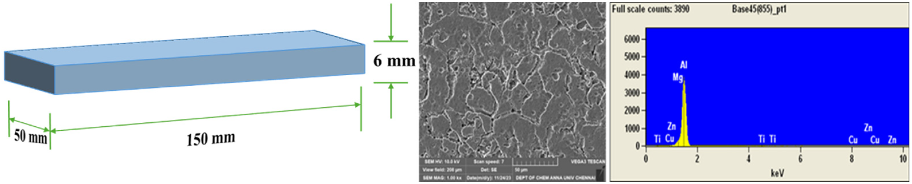
SEM EDX of AA5083 alloy.
Chemical composition and mechanical properties of the AA5053 alloy.
Laser shock peening
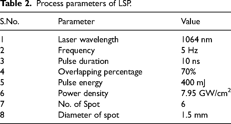
In a typical LSP setup, an absorbing layer shields the sample surface, and a confining layer intensifies the shock wave's pressure and duration. A high-energy pulsed laser beam penetrates the confining layer and irradiates the absorbing layer, triggering plasma formation. When the shock wave goes past the Hugoniot elastic limit, it causes plastic deformation, changes in the microstructure, and CRS close to the material's surface. This comprehensive understanding of the materials and parameters involved in the LSP process is crucial for achieving the desired strengthening effects. A Q-switched Nd:YAG laser system (YS80-M165) was used to finish laser shock processing experiments. Table 2 lists the detailed laser parameters. 19 A 0.1-mm-thick layer of aluminum tape was applied to the specimens before LSP to shield the LSP-treated surface from laser thermal damage. In order to enhance the absorption of laser energy, a confining layer made of circulating water, measuring approximately 1 mm in thickness, was used to cover the treated surface during the LSP treatment.
Process parameters of LSP.
Mo-thermal coating using HVOF process
HVOF coating, potentially exemplifying the forefront of anti-wear coating applicable across various shipbuilding operations, are applied to both untreated and LS-treated substrates. Specifically, molybdenum wire (GK MIN MET Alloy Co., India), with a purity of 99.6% and a diameter of 3.175 ± 0.02 mm, served as the primary material for creating coating samples. The coating is applied to untreated and LSPT-treated AA5053 substrates with a dimension of 10 × 10 × 6 mm2. Prior to the spraying process, the substrates underwent a cleaning step using acetone for 3 min to ensure proper adhesion of the coating.20,21 The experimental procedure for W_HVOF coating involved using oxygen and LPG as fuel. Process parameters had been fine-tuned beforehand to achieve optimal outcomes, including a dense microstructure, mechanical characterization, tribological characterization, and efficient deposition. Table 3 displays the optimized parameters. The thermal spray coating utilizing W_HVOF technology was conducted using equipment from AUM Surface Technology Industry (Manufacturer: Praxair-Tafa, Concord, NH, USA), employing wire as the feedstock. This choice significantly impacts the economic aspect of the process, as wires are generally more cost-effective than powders. Moreover, the operational expenses associated with this method are lower compared to alternative thermal spray processes. The key advantage of this system lies in its ability to attain temperatures sufficient for wire melting and ensure high atomization during the W_HVOF process.22,23 As a result, the system melts the wire droplets completely, producing coatings free of unmelted or semi-molten particles. The substrates were compared based on their mechanical, tribological, and corrosion characteristics. A study was conducted to compare the mechanical, tribological, and corrosion characteristics of four different substrates: untreated (UNT), untreated + coating (UNTC), LSP-treated (LSPT), and LSP-treated + coating (LSPTC).
Process parameter of HVOF coating.
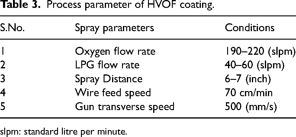
slpm: standard litre per minute.
Mechanical and corrosive properties
The Nano indentation of the four different substrates: UNT, UNTC, LSPT, and LSPTC was measured on the top surface using a TR-101, DUCOM, Netherlands, indentation tester with a load of 10N (1 kgf)–60N (6 kgf) and a dwell time of 15 s. Nanoindentation was measured using the ASTM E-92 standard. 24 The samples were sectioned into 10 × 10 mm squares, cleaned with acetone, and polished with 400–1500-grit sandpaper for a mirror-like surface. Industrial components that operate under severe heat and fatigue loading conditions require precise information on surface roughness, which the LSP process causes. We measured the surface roughness in the longitudinal (X) and transversal (Y) directions using the Taylor Hobson Surtronic S-128 roughness measurement equipment. We took the measurements using a cut-off length of 0.8 mm and a measurement length of 4 mm, traveling at a speed of 0.6 mm/s.25,26 All roughness measurements were taken three times, and better values are reported.
Scratch test (TR-101, DUCOM, Netherlands) were conducted using a Rockwell dimond indenter (100 μm tip radius) in a progressive mode (track 6 mm, scratch speed 1 mm/min, load 10N to 60 N) at approximately 25° C and 50% RH. 27 The 3D coating morphology allows for accurate calculation of the volume of plastic pileups (VPILE), scratch ditches (VDITCH), their sum (VP + D), and entire scratch grooves (VGROOVE). The Linear reciprocating wear tests (LRT) were performed using a ball-on-disk sliding wear tester (THT 1000 and TRB3, Anton Paar, Austria). The hardened EN steel ball (Ra < 0.1 m, hardness 65 HV, and diameter 8.1 mm) was used as a pin on plate samples at a sliding distance 100 m, stoke length 8 mm, normal load 10N and frequency 4 Hz at a room temperature (25 °C).28,29 The frictional coefficient was determined with a precision of ±0.005. The schematic diagram of Scratch and LRT wear test instruments are shown in Figure 2. The wear loss and worn track are observed using SEM.
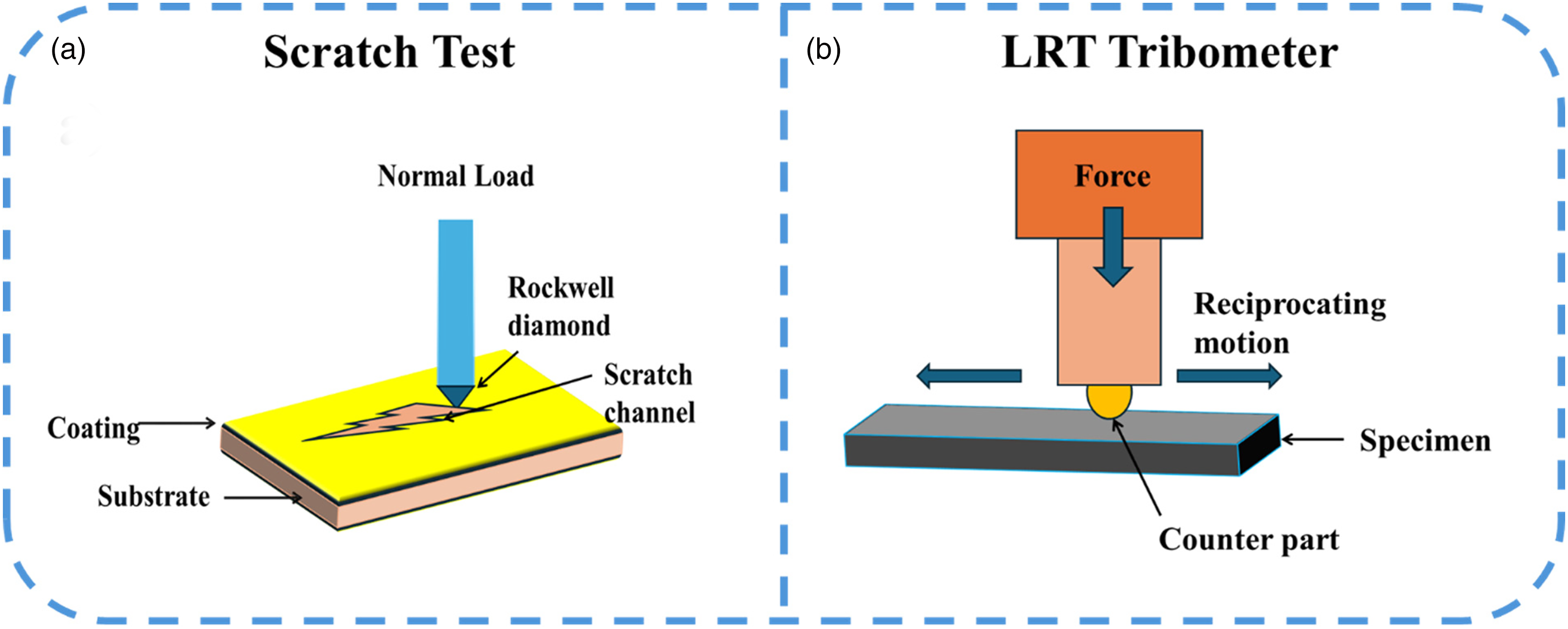
Schematic view of Scratch and LRT tribometer instrument.
For electrochemical corrosion experiments, the GAMRYTM Potentiostat model: Interface 1010E was used to process a 10 mm × 6 mm specimen. The electrochemical corrosion experiment involved with three electrodes: the working (specimen), reference (Ag/AgCl), and auxiliary electrodes (SCE). We submerged the specimens in a 3.5% NaCl solution for 15–20 min to achieve a consistent open circuit potential. 30 The dynamic potential scanning method was then used to determine diverse specimen's potentiodynamic polarization parameters and AC impedance parameters. The scan rate was 2 mV/s, 31 with potential range at − 1 V and +1 V vs reference electrode, respectively. 32
Three specimens with the same parameters were used in each electrochemical corrosion experiment. The contact angle was measured using Goniometry instrument (Pheonix 300 model; SEO, Korea) by droplet volume of 10 μL distilled water to inspect the surface wettability characteristics. All the experiments were done with three trials and the better results was represented.
Microstructure characterization
The specimens were prepared for FESEM analysis by electrochemical polishing using a solution of 10% perchloric acid in ethanol at 20 V for 10sec. FESEM imaging was conducted using a ZEISS EVO 10 instrument with the following settings; acceleration voltage of 20 kV, probe current of 18.1 nA, working distance of 17–18 mm, tilt angle of 70°, and scanning step size of 1.5 μm. AZtecCrystal software was used to analyze the SEM data. Crystallographic phase and precipitate formation were determined using X-ray diffraction (XRD). Measurements were acquired on a Bruker D8 diffractometer using Cu Kα radiation (λ = 1.504 Å) at 20 kV and 5 mA. A Cr filter was employed, and the 2θ angle was scanned from 10° to 90° with a step size of 0.02°. Residual stress analysis was performed using the Debye-Scherrer method and the Sin2Ψ method.
Result and discussion
FESEM analysis
The performance of HVOF molybdenum coatings on AA5083 aluminum alloy depends on two key factors: porosity and thickness. Porosity refers to tiny air gaps or voids within the coating, while thickness influences how well the coating can protect the material. This comparison looks at the porosity and thickness of HVOF Mo coatings on AA5083 for two types of specimens UNTC and LSPTC specimens. The average thickness of the both UNTC and LSPTC specimens is around 50 ± 3 µm, which is shown in SEM images Figure 3 and 4.
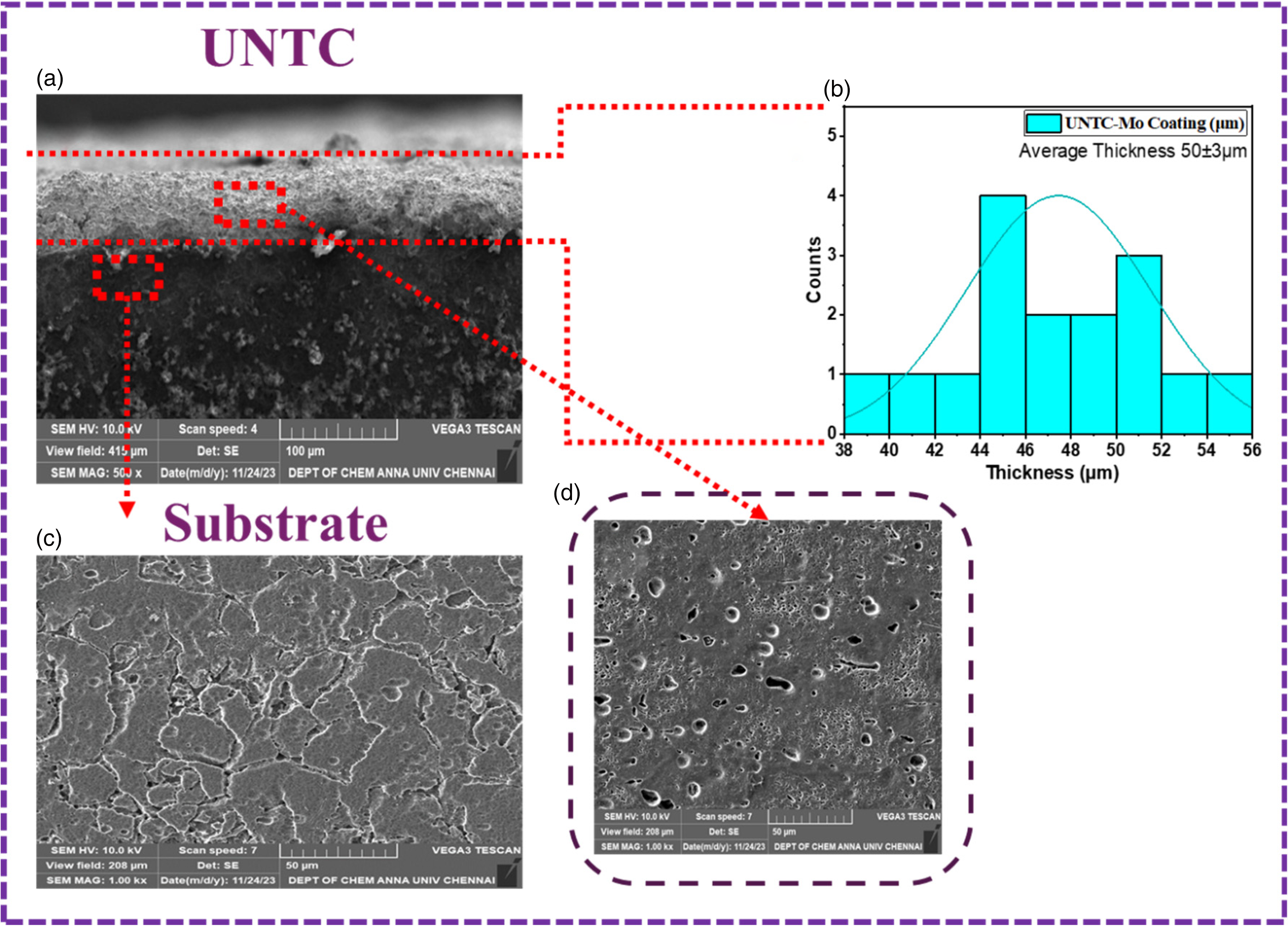
SEM image of UNTC specimens.
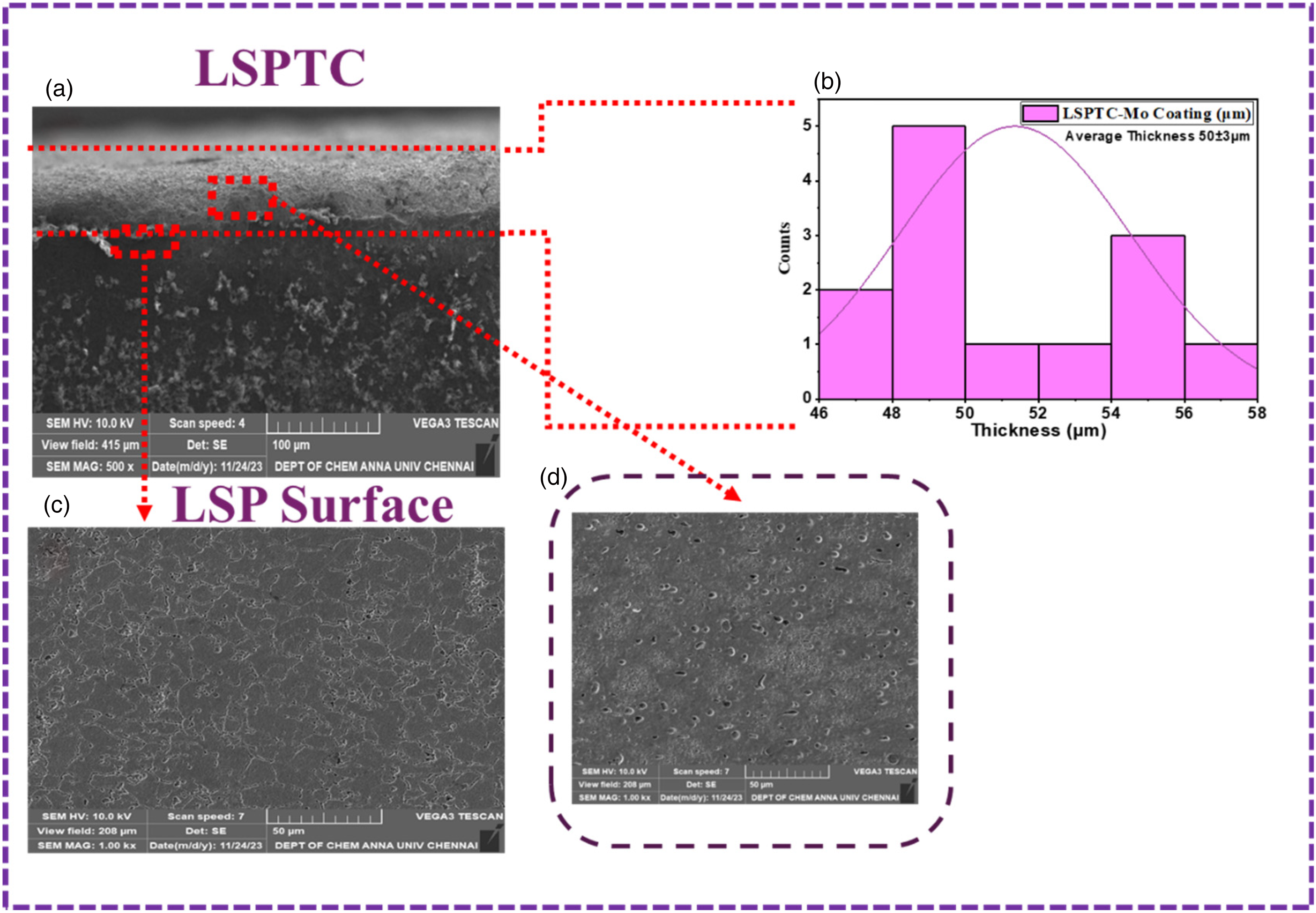
SEM image of LSPTC specimens.
In Figure 3. UNTC specimens, some level of porosity is unavoidable due to the nature of the HVOF coating on the smooth surfaces. These pores weaken the coating by acting as stress points, which reduces mechanical strength and fatigue life. Additionally, the pores can allow corrosive substances to penetrate and reach the aluminum substrate. LSP, a pre-treatment method, uses laser pulses to introduce compressive stresses into the Figure 4. LSPTC specimen. These stresses help to collapse some of the pores, making the coating denser and reducing its porosity. Less porosity means the coating is stronger, more resistant to fatigue, and offers better protection against corrosion. The LSP treatment doesn't change the coating thickness significantly. However, after the LSP treatment the coating reduces the chances of substrate warping and lowers the stress at the interface between the coating a8nd substrate. Generally, the porosity of the UNTC specimen ranges from 1% to 5%, while LSPTC specimens show reduced porosity, ranging from 0.5% to 3%, due to pore collapse. LSP improves mechanical strength, fatigue resistance, corrosion protection, and reduces the risk of substrate warping.
Nano indentation test
The nano indentation test was performed on four specimens UNT, LSPT, UNTC, and LSPTC. The test involved progressively increasing the load on a diamond tip while measuring how deeply it penetrated the material (with a depth ranging from 0 to 100 nm). It was noteworthy that all specimens had their highest hardness values on the surface, within a fairly shallow range of 5–15 nm. All four specimens in Figure 1(a) require a greater force to achieve the same indentation depth. This trend suggests a phenomenon known as film hardening. The test also revealed clear differences in hardness between the specimens, as shown in Figure 5(a). Figure 5(b) presents the hardness values obtained from the dynamic stiffness measurements for all the specimens. Figure 5(b) provides a visual comparison of the hardness values across the various materials tested. The software employed the Oliver-Pharr method to calculate hardness and elastic modulus from the force-depth curves generated during the experiment (as shown in Figure 6). The UNT substrate specimen has the lowest hardness (2.54 ± 0.02 GPa), followed by the LSPT (3.04 ± 0.02 GPa), which showed a noticeable improvement. The UNTC (4.16 ± 0.03 GPa) was significantly harder than the uncoated aluminum, highlighting the inherent strength of molybdenum. Lastly, the combination of molybdenum and laser shock peening may have contributed to the LSPTC's highest overall hardness of 4.66 ± 0.02 GPa. The nanohardness values and Young's modulus values for each specimen show the same trend, materials that are stiffer tend to be harder (UNT = 70.54 GPa, LSPT = 161.7 GPa, UNTC = 312.71 GPa, and LSPTC = 395.42 GPa). Factors like tip geometry and surface condition, particularly near their surfaces, can influence nanoindentation results. The LSP and molybdenum coatings are effective strategies for enhancing the surface hardness of AA5053 aluminum alloys. 33
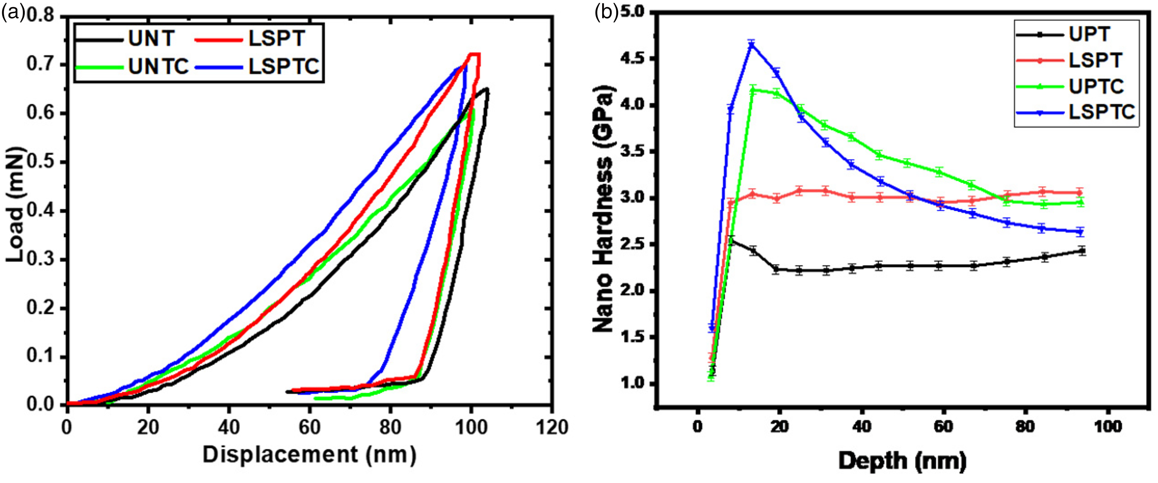
(a) load displacement curve and (b) Nano hardness depth curve of UNT, LSPT, UNTC, and LSPTC specimens.
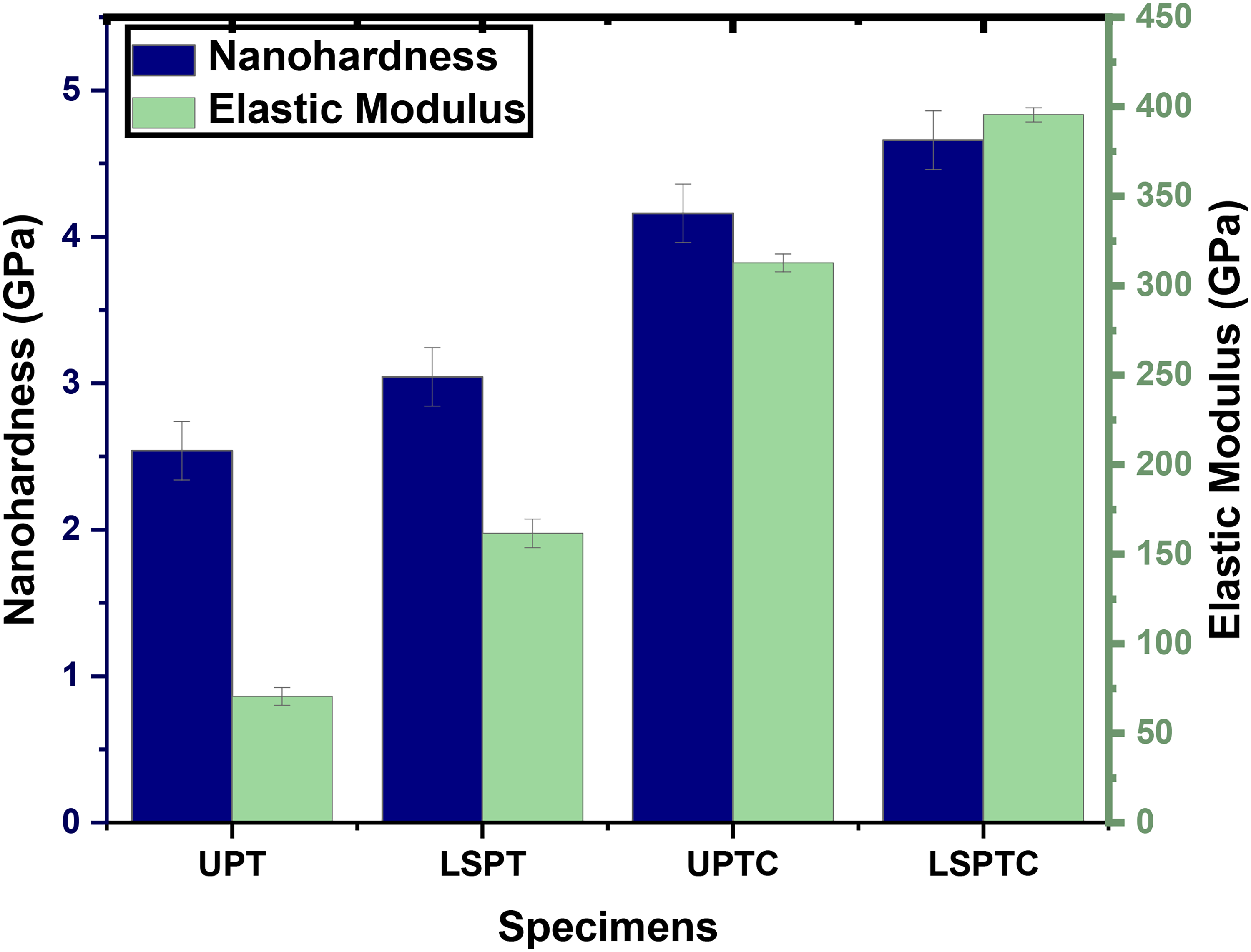
Nanohardness and Elastic modulus bar chart for UNT, LSPT, UNTC, and LSPTC specimens.
Surface roughness analysis
Surface roughness is a critical parameter for evaluating material properties such as friction, wear, and adhesion in various engineering applications. The Arial 3D surface roughness test provides a detailed topographical map of the surface, along with the measurement of Ra (average roughness) of four specimens are shown in Figure 7 (a) & (b). UNT Substrate (Ra = 0.467 µm) has a relatively low surface roughness. This indicates a smoother surface compared to the other specimens. However, the lack of surface roughness could reduce adhesion for coatings or surface treatments, which might negatively impact coating durability. The LSPT specimen shows a significant increase in roughness, with an Ra of 1.423 µm. This increase is due to the mechanical impact of the LSP process. LSP induces compressive residual stresses on the surface, improving fatigue life and resistance to crack initiation. The roughened surface promotes better mechanical bonding and adhesion if coatings are applied afterward. However, the increased surface roughness may also lead to higher friction and wear if used in sliding or contact applications without further treatments. The UNTC specimen shows the highest roughness value, with an Ra of 5.396 µm. The high roughness is a result of the HVOF spraying process, which deposits molten or semi-molten particles onto the surface, creating a rough, uneven surface texture. The increased surface area and mechanical interlocking of the coating are advantageous for improving adhesion strength and coating durability. However, such high roughness could lead to higher friction and wear in applications involving sliding contact, unless the surface is further polished. The LSPTC specimen exhibits a reduced surface roughness compared to the UNTC specimen, with an Ra of 4.354 µm. The surface roughness is still relatively high due to the molybdenum coating, but the prior LSP treatment has helped to smooth the surface slightly, possibly due to the compressive stresses that may alter the topography during coating. This combined treatment improves the mechanical properties of the 5083 aluminum alloy, particularly in fatigue and wear resistance, while also providing enhanced corrosion protection from the molybdenum coating. The roughness reduction compared to the UNTC specimen indicates that LSP can be beneficial in creating a balance between improved surface toughness and moderate surface roughness.
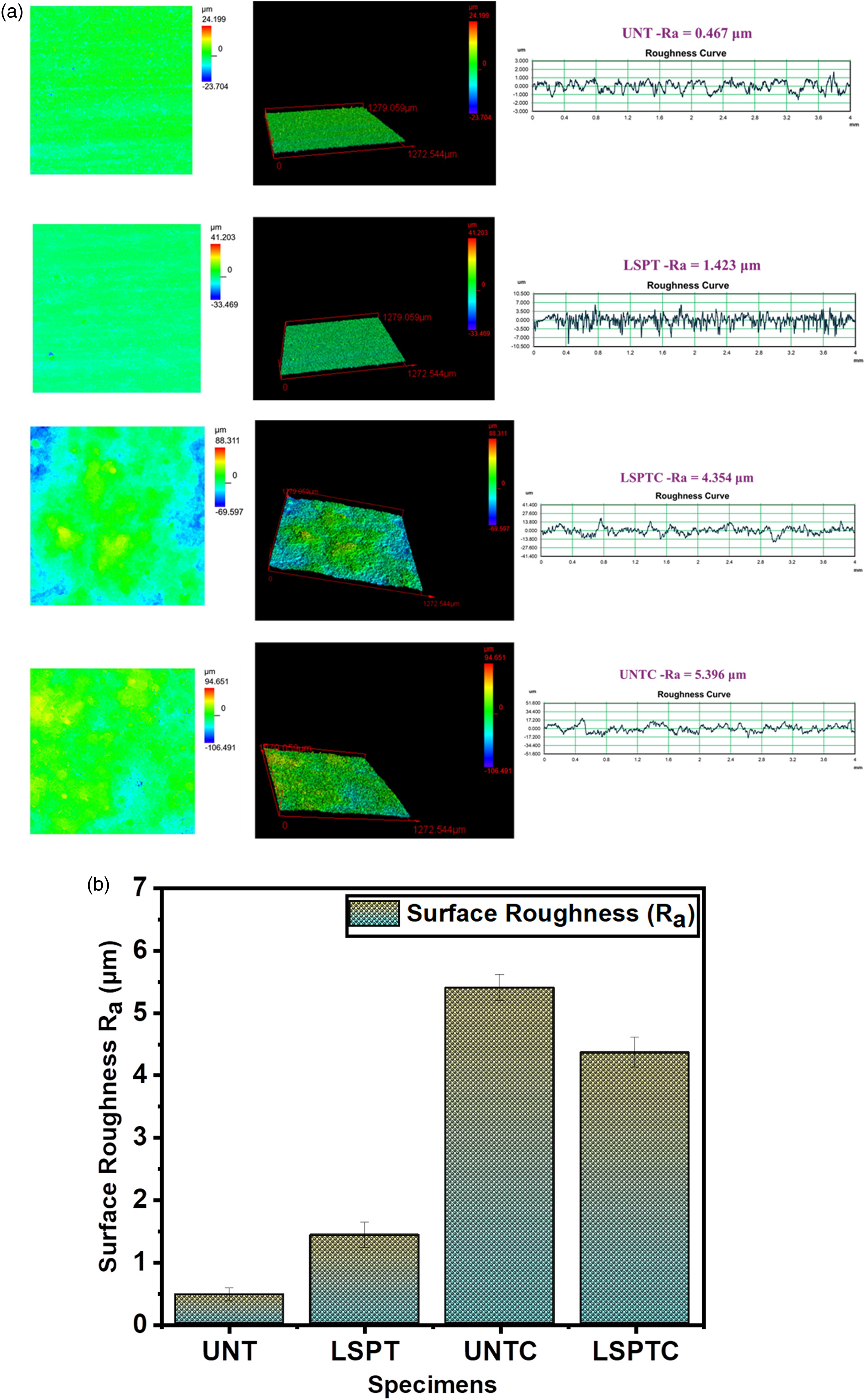
(a) & (b) Surface roughness (Ra) of UNT, LSPT, UNTC, and LSPTC specimens.
Scratch analysis
A scratch test can be used to assess the wear resistance of these on the UNT, LSPT, UNTC, and LSPTC four specimens by plotting the traction force needed to scratch the surface against the stoke distance the scratching tool travels. Figure 1(b). graph shows a rise in force initially as the tool digs into the material, followed by a plateau or slight decrease as the scratch progresses. During the test, the UNT substrate specimen likely had the lowest overall force required for scratching. The LSPT specimen may slightly increase the initial and overall force by introducing compressive stress that resists crack formation. Due to the superior hardness of molybdenum, we expect the AA5053 unpeened aluminum alloy with a molybdenum coating to exhibit a significant jump in required force. Lastly, the molybdenum coating on LSPTC combination is likely to show the highest and most stable force throughout the test. This means that it will be the least likely to scratch when the material's hardness and work hardening from the peening process are added together. Sudden spikes in force on the graph for any material could indicate chipping or fracturing during the test, while the overall smoothness of the curve can reveal variations in surface properties.
Figure 8(a) and 8(b). graphs can provide valuable insights into the wear resistance of four specimens: UNT, LSPT, UNTC, and LSPTC. The graph tracks two key parameters, namely, the constant downward force (normal load) applied by the scratching tool and the distance it travels (stroke length). Throughout the test, the UNT substrate specimen displayed the lowest and most consistent normal load. This suggests that the softer AA5053 aluminum surface requires less force to produce a scratch. Because of the increased surface hardness, LSPT might result in a slightly higher, but still relatively stable, normal load. We expect the UNTC to pose a significant challenge for the scratching tool, necessitating a significantly higher than normal load from the outset. This is because molybdenum is a far harder material than aluminum. The natural hardness of the molybdenum in the LSPTC specimen and the work hardening effect of laser shock peening should match the highest and most stable normal load needed for the scratch test. The graph for this specimen might show a sharp rise in load initially, followed by a steady value, indicating exceptional resistance to penetration. The normal load vs. stroke length scratch test offers a clear comparison of wear resistance. The molybdenum coating, especially when hardened by laser shock peening, is expected to outperform the others by requiring the highest and most stable normal load to produce a scratch.
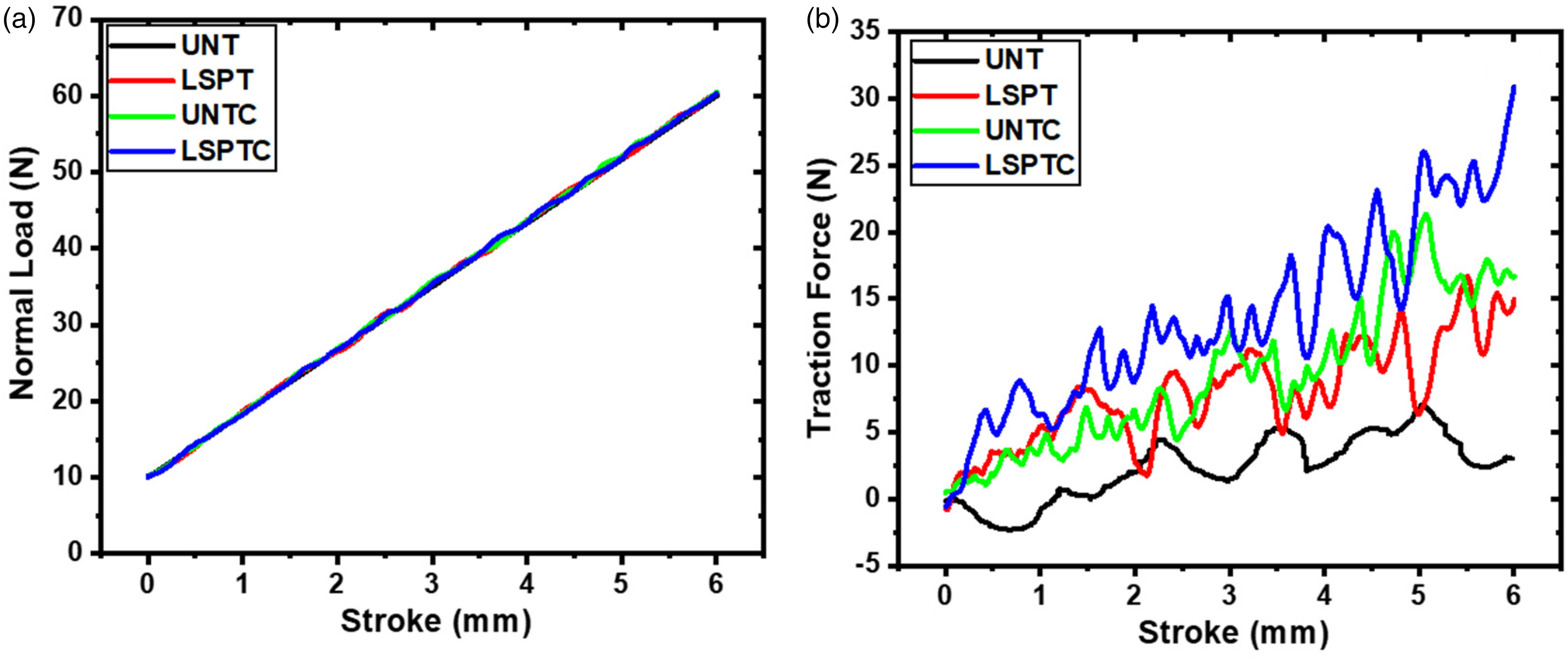
(a) normal load vs Stroke graph and (b) Traction force vs stroke graph.
The normal load vs. stroke length graph, as discussed earlier, reveals wear resistance. Here, the UNT substrate specimen shows the lowest and most consistent normal load, while the LSPTC likely requires the highest and most stable normal load to penetrate due to its superior hardness. Figures 9(a) and 9(b) show how the graph demonstrates how the friction between the scratching tool and the material changes as the scratch progresses. The UNT substrate specimen might exhibit a constant friction coefficient throughout, indicating consistent interaction with the soft aluminum. The LSPT specimen could show a slight rise initially due to work hardening, followed by a potential decrease. Due to their hardness, we expect UNTC to have a higher initial friction coefficient compared to the substrate. As the scratch reaches the aluminum substrate, it may decrease slightly. The LSPTC specimen might follow a similar trend, but with a potentially higher overall friction coefficient due to the combined effects of hardness and work hardening. This test offers a clear comparison of scratch resistance with molybdenum coatings, especially when combined with laser shock peening, demonstrating the best performance.
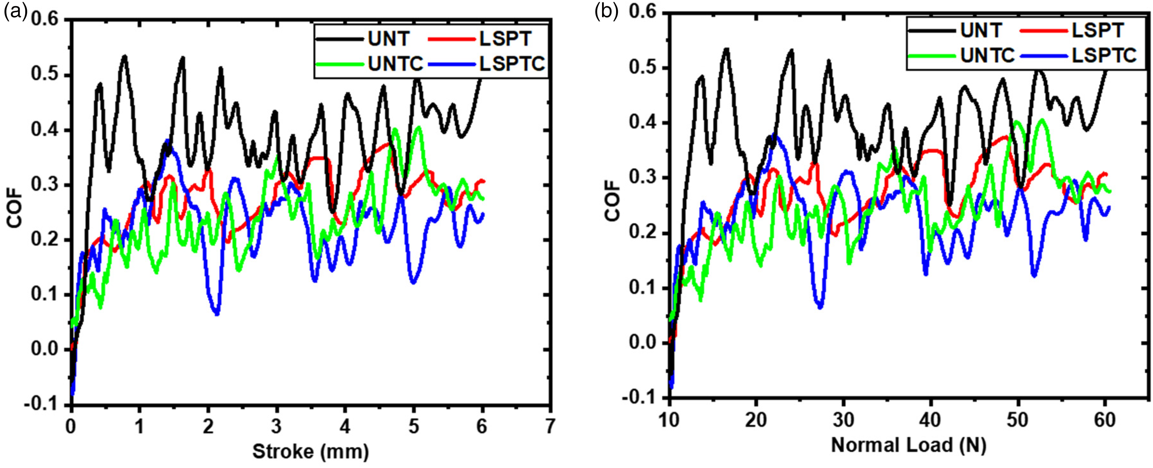
(a) COF vs stroke graph and (b) COF vs normal load graph.
LRT wear analysis
The LRT wear test was conducted to assess the wear behavior of four specimens. The test analysed the coefficient of friction (COF) between the specimens and a contacting surface under two different loads (5N and 10N) are shown in Figure 10. Figure 11 shows the comparative COF bar graph of the all specimens. The UNT substrate specimen exhibited a moderate COF at both loads, indicating some friction during sliding. This COF might change slightly over time, depending on the wear mechanism (plowing or adhesion). The higher load of 10N resulted in a higher COF compared to the 5N load due to increased plastic deformation and adhesion (5N COF = 0.6949 and 10N COF = 0.8079). The LSPT specimen appears beneficial for reducing friction. The LSPT substrate had a lower COF than the UNT substrate specimen when the 5N load was applied. This is likely because the compressive stress from shock peening made it less likely to plough and stick together. The COF may even decrease slightly as the surface smooths out. The effect of LSP was less pronounced at the higher load (10N), but the COF remained potentially lower than the UNT substrate specimen (5N COF = 0.5729 and 10N COF = 0.7757). Molybdenum's inherent hardness is evident in the consistently lower COF of the UNTC specimen compared to the aluminum specimens at both loads. This suggests minimal adhesion between the molybdenum coating and the contacting material. The COF may even decrease slightly due to potential polishing of the coating during the test (5N COF = 0.502 and 10N COF = 0.596). The LSPTC specimen combines the advantages of both molybdenum's hardness and friction reduction from LSP. Overall, it had the lowest COF across both loads, indicating potentially superior wear resistance. The COF trend might remain constant or even decrease slightly due to polishing effects (5N COF = 0.3098 and 10N COF = 0.3555).

COF vs Time graph with 5 and 10N load condition graph.
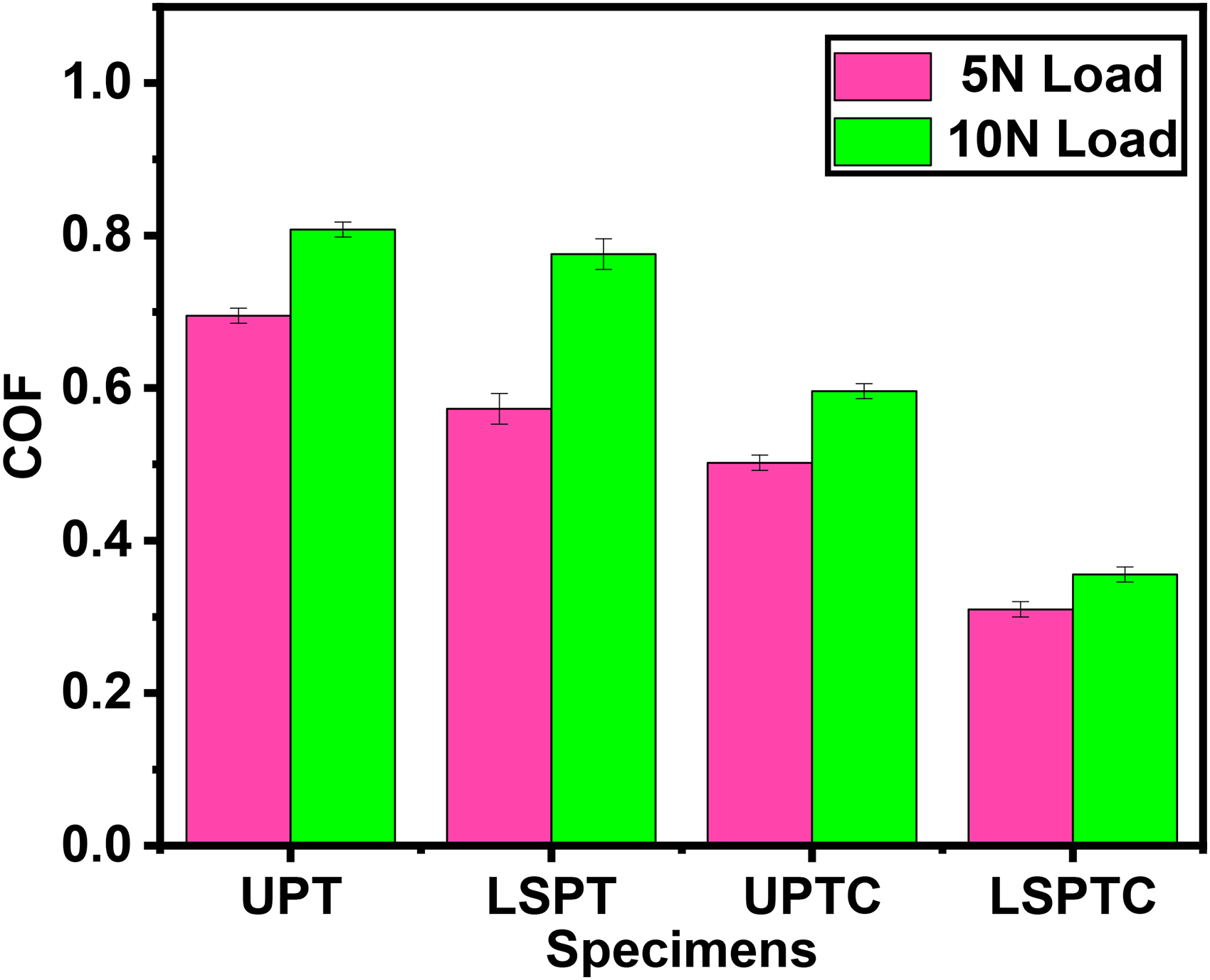
COF plot of 5N and 10N load condition graph.
Figure 12 displays the wear rates of four specimens UNT, LSPT, UNTC, and LSPTC. The UNT substrate specimen exhibits a moderate wear rate at 5N (0.00284 mm³/N/m). The higher load leads to a higher wear rate, as expected, due to increased contact pressure and plastic deformation at 10N (0.00358 mm³/N/m). The LSPT specimen wears down less quickly than the UNT substrate. This might be because the UNT substrate adds compressive stress, which makes it harder for material to be removed when it slides at 5N (0.00216 mm³/N/m). The wear rate remains lower or shows a minimal increase compared to the UNT substrate at 10N, suggesting continued benefit from the LSP process even under a higher load at 10N (0.00228 mm³/N/m). Molybdenum-coated aluminum alloy UNTC specimen inherent hardness likely results in the lowest wear rate compared to UNT specimen at 5N (2.336 × 10⁻⁴ mm³/N/m). The wear rate increases slightly compared to 5N but remains significantly lower than the aluminum specimens at 10N (2.76 × 10⁻⁴ mm³/N/m). This indicates the good wear resistance of the molybdenum coating. The LSPTC specimen has the lowest overall wear rate. This is because it combines the benefits of molybdenum's hardness with the possibility of less wear from the LSP process. The wear rate increases slightly but remains the lowest among all specimens at both loads at 5N (1.577 × 10⁻⁴ mm³/N/m) and 10N (2.196 × 10⁻⁴ mm³/N/m).
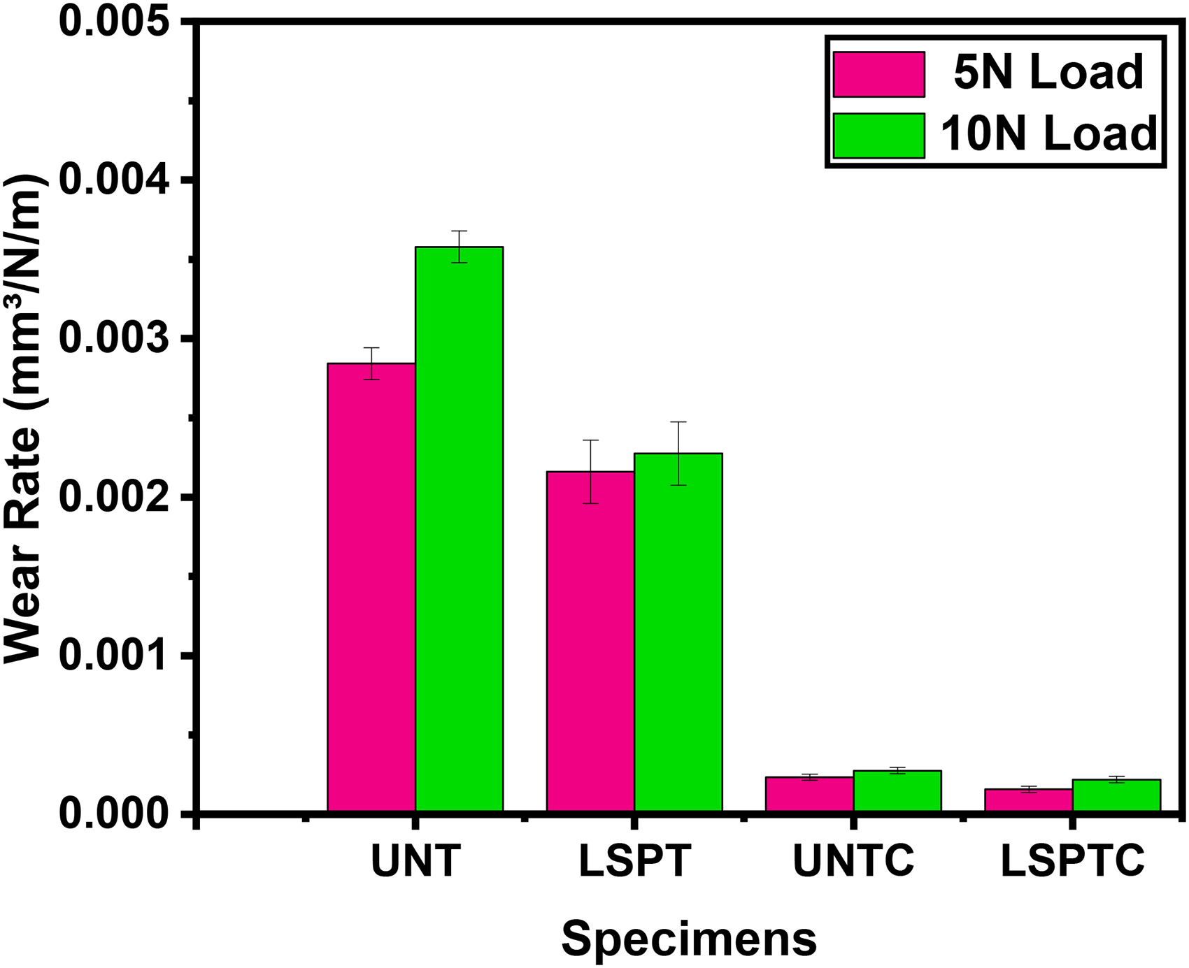
Wear rate graph of UNT, LSPT, UNTC, and LSPTC.
The results suggest that molybdenum coatings, especially when LSP treatment, offer superior wear resistance based on their lower COF values. This indicates less friction and potentially lower wear rates during sliding contact. Wear track morphology analysis after the test can provide complementary information about the wear mechanisms (plowing, adhesion, fatigue) for each specimen.
Contact angle measurement
The contact angle test assesses the wettability of a material's surface by measuring the angle formed between a liquid droplet and the solid surface. Figure 13 displays the results for the four specimens (UNT, LSPT, UNTC, and LSPTC). The UNT substrate specimen (48.9°) relatively has a low contact angle, which indicates a more hydrophilic (water-loving) surface. The liquid droplet spreads more readily on the aluminum, resulting in a smaller angle. The LSPT specimen (88.4°) shows significant increases in the contact angle compared to the UNT substrate. This suggests a change towards a more hydrophobic (water-repelling) surface. The rougher texture introduced by LSP traps air pockets at the liquid-solid interface, leading to a larger contact angle. UNTC (93.2°) has a molybdenum coating that exhibits an even higher contact angle than the LSPT specimen. Molybdenum itself is generally considered more hydrophobic than aluminum, contributing to this increase. The LSPTC specimen (103°) demonstrates the highest contact angle, showcasing the most hydrophobic surface. It combines molybdenum's inherent hydrophobicity with the additional effect of LSP surface roughness, resulting in the largest contact angle. The contact angle measurements provide valuable insights into these specimen's surface wettability. The result suggests that LSP and HVOF molybdenum coatings significantly alter the surface properties, making them more hydrophobic. It is relevant for applications where water repellency is desired, such as self-cleaning surfaces or corrosion protection.
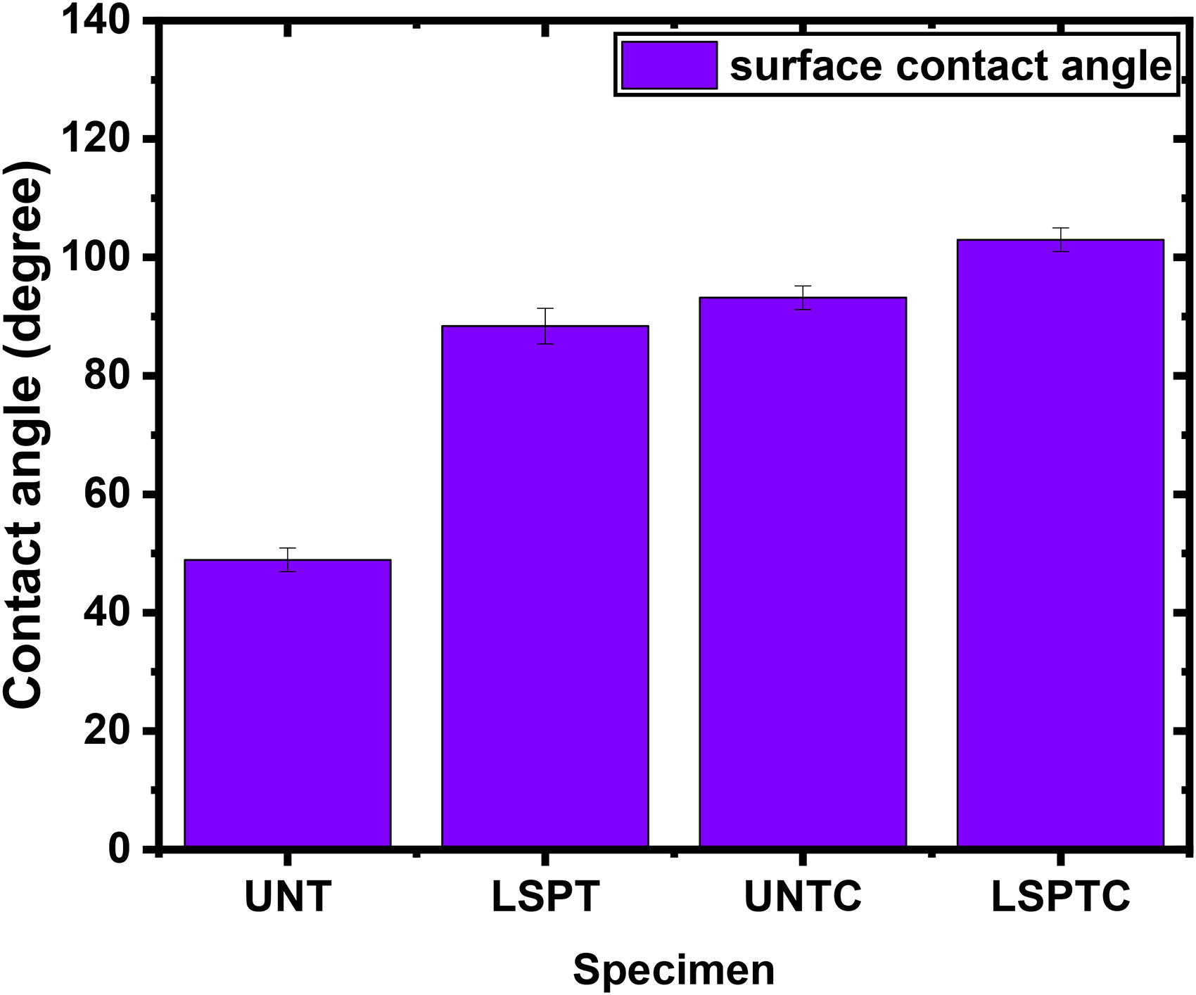
Contact angle measurement of UNT, LSPT, UNTC, and LSPTC specimens.
Electrochemical corrosion analysis
Figure 14 shows the polarisation for corrosion graph for all four specimens. The UNT specimen exhibited the highest corrosion rate among the all specimens. This is because aluminum, while having a naturally protective oxide layer, is more susceptible to corrosion in aggressive environments without additional surface treatment. The high corrosion rate indicates significant material degradation over time when exposed to corrosive environments. The Laser peening introduces compressive residual stresses and improves the surface hardness, which contributes to enhanced corrosion resistance of the LSPT specimen. The molybdenum coating drastically reduces the corrosion rate compared to both UNT and LSPT specimens. Molybdenum acts as a barrier layer, preventing corrosive agents from penetrating the aluminum substrate. This low corrosion rate demonstrates the effectiveness of molybdenum in providing excellent corrosion protection in aggressive environments. The combination of LSP process and molybdenum coating results in the lowest corrosion rate among molybdenum coating on pure aluminium alloy specimens. Table 4. Shows the electrochemical corrosion data values. The electrochemical corrosion tests demonstrate that the LSPTC specimen (32.30 X 10⁻⁸ mm/year) exhibits the best corrosion resistance. This is followed by the UNTC corrosion rate of 28.446 X 10⁻⁷ mm/year. Both UNT and LSPT specimen showed higher corrosion rates, with the UNT being the least corrosion-resistant. The LSP enhances the mechanical strength of the coating, while the molybdenum provides superior corrosion protection. This synergy between the two treatments leads to a significant improvement in both corrosion resistance and overall material performance, making this treatment ideal for applications where both high mechanical strength and corrosion resistance.
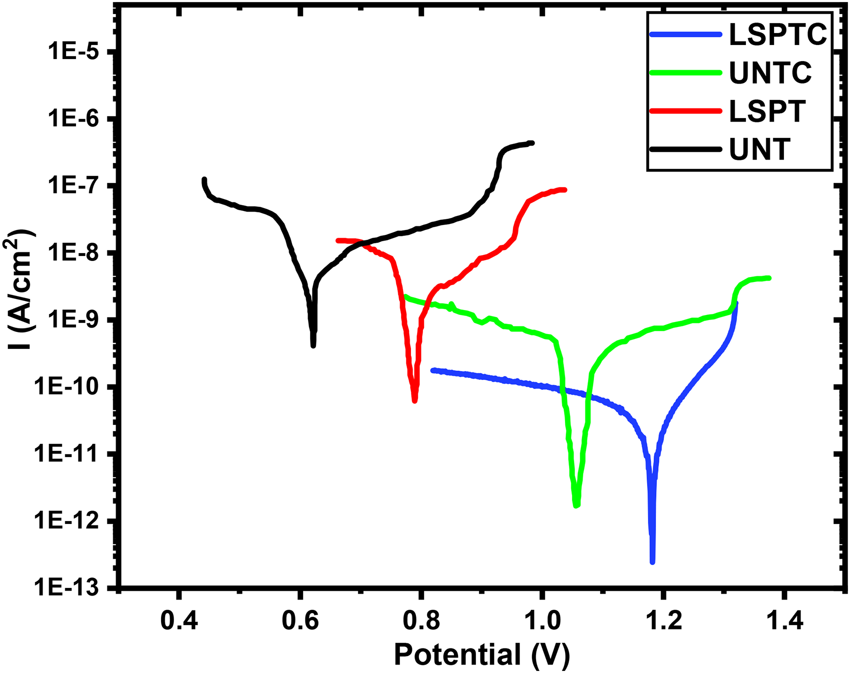
Tafel plot of UNT, LSPT, UNTC, and LSPTC specimens.
Comparative values of electrochemical corrosion testing.
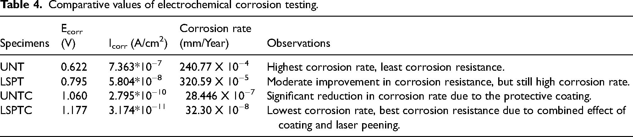
Figure 15 shows the SEM images of four corroded specimens. The UNT aluminum alloy exhibited the most severe corrosion damage. The presence of large cracks and deep pits indicates that the alloy is susceptible to pitting corrosion, a localized form of corrosion that can lead to catastrophic failure. In LSPT specimen, a surface treatment process that introduces compressive residual stresses, improved the corrosion resistance compared to the pure alloy. However, the presence of moderate-sized cracks and pits suggests that the laser peening treatment did not fully eliminate the susceptibility to pitting corrosion. The UNTC specimen, Mo provided some protection against corrosion, as evidenced by the smaller size of the corrosion pits compared to the pure alloy. However, the presence of porous holes and cracks indicates that the coating was not completely uniform or adherent, allowing corrosive agents to penetrate and attack the underlying AA5053 aluminum. In LSPTC specimen, combination of treatments demonstrated the most effective corrosion resistance. The compressive residual stresses introduced by laser peening likely enhanced the adhesion of the molybdenum coating, reducing the likelihood of coating delamination and providing better protection against corrosion.
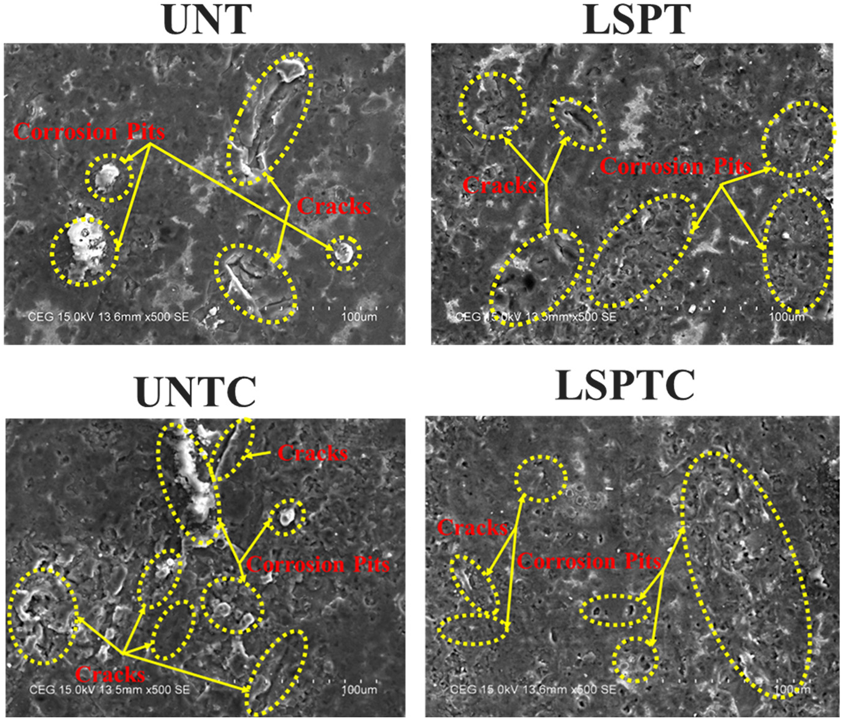
SEM image of corroded specimens.
XRD analysis
The XRD analysis provides insights into the crystallographic changes, phase composition, and microstructural modifications of the 5083-aluminum alloy and its surface treatments. Figure shows the comparison of the XRD results for the UNT, LSPT, UNTC and LSPTC four specimens (Figure 16).
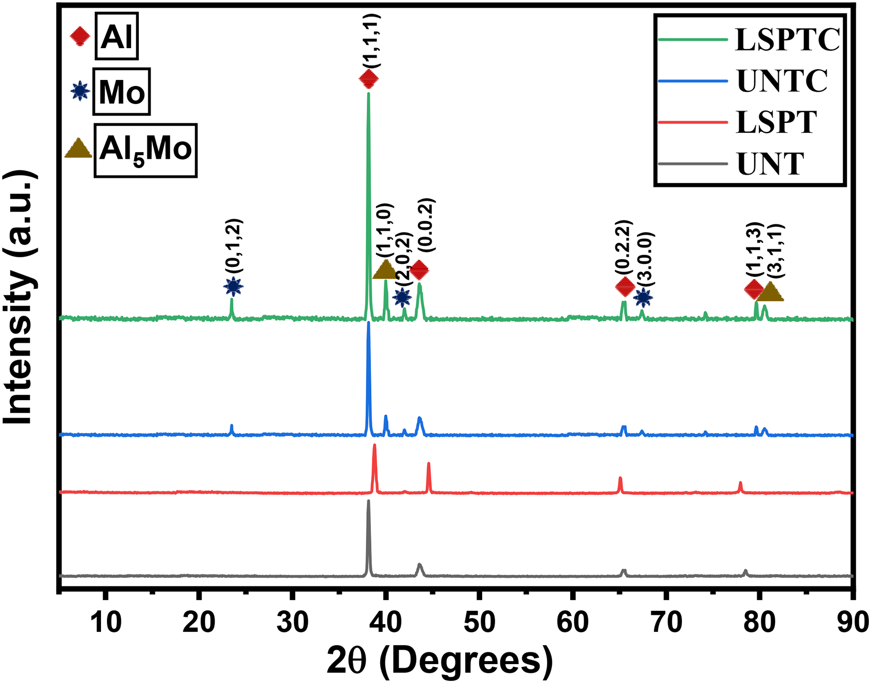
XRD analysis of UNT, LSPT, UNTC, and LSPTC specimens.
UNT has a large peak is observed at a 2θ angle of 38.22°. This peak corresponds to the dominant Al phase in the untreated 5083 alloy. The sharpness of the peak suggests a relatively coarse grain structure, as is typical of UNT specimen. The peak position remains constant, indicating no significant residual stress or phase transformations.
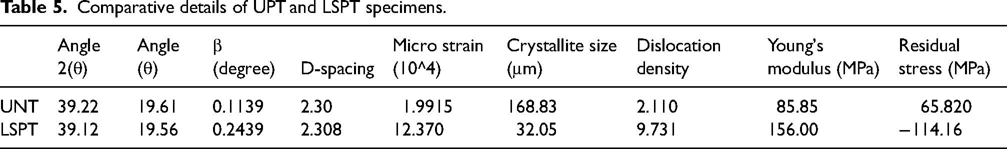
LSPT has a same large peak at 2θ = 39.12°, with peak shifting and peak broadening. The peak at 38.12° experiences a slight shift due to the introduction of compressive residual stresses from the LSP process. This stress compresses the crystal lattice, leading to a shift in the diffraction angle. Their broadening is indicative of grain refinement. LSP introduces high-energy impacts that result in ultra-fine grain formation, leading to a broader XRD peak. The refinement of the grain size enhances mechanical properties of strength and hardness, in the LSPT specimen. Together, the peak shift and broadening highlight the microstructural modifications and the enhanced mechanical performance of the LSPT compared to the UNT. The Table 5 shows the detail surface enhancement of the UPT AND LSPT specimens using XRD graph.
Comparative details of UPT and LSPT specimens.
UNTC specimen has XRD Peaks; Molybdenum (Mo) peaks at 2θ = 23.47°, 42.07°, and 67.22°; Al₅Mo precipitate peaks at 2θ = 39.97° and 80.32°. The presence of Mo peaks indicates the successful deposition of molybdenum on the AA5083 substrate. The appearance of Al₅Mo precipitate peaks suggests that the molybdenum reacts with the aluminum substrate, forming intermetallic compounds. These compounds typically enhance the hardness and wear resistance of the coated AA5083 alloy. These peaks are characteristic of the molybdenum crystalline structure, Mo and Al₅Mo suggests that the coating showing a well-defined coating on the surface without significant strain or grain refinement.
LSPTC specimen has the peaks same as the UNTC specimen. The presence of Mo and Al₅Mo peaks is consistent with the UNTC. However, the key difference here is the observed peak shifting and broadening due to the LSP process. Similar to the LSPT specimen, the Mo and Al₅Mo peaks exhibit slight shifts, indicating the presence of compressive residual stresses induced by the LSP process. These stresses enhance the strength of the coating, making it more resistant to deformation and cracking under mechanical loads. The broadening of Mo and Al₅Mo peaks suggests grain refinement within the molybdenum coating and intermetallic phases. This fine-grained structure enhances the overall mechanical properties, particularly the wear and fatigue resistance of the coating. The combined effects with combination of peak shifting and broadening indicates that the LSPTC benefits from enhanced strength and durability compared to the UNTC. The introduction of residual compressive stresses and grain refinement makes the LSPTC specimen mechanically superior to the pure molybdenum-coated aluminum alloy.
Conclusion
This study comprehensively evaluated the impact of dual-treatment of LSP and molybdenum coatings on AA5083 aluminum alloy, highlighting significant improvements in mechanical properties, wear resistance, and corrosion protection. Nanoindentation results showed that both LSP and Mo coatings significantly increased surface hardness and Young's modulus, indicating improved material strength. Surface roughness analyses revealed that while LSP alone increased roughness, the Mo coatings further amplified this effect, which may enhance adhesion and friction properties. In scratch tests, both treatments, particularly when combined, led to enhanced scratch resistance. The wear analysis indicated that LSP and Mo coatings reduced the coefficient of friction and wear rate, confirming superior wear resistance. Contact angle measurements showed that both treatments made the surface more hydrophobic, potentially improving corrosion resistance and reducing wettability.
Additionally, electrochemical corrosion analysis demonstrated that LSP and Mo coatings drastically reduced corrosion rates, enhancing the material's longevity in harsh environments. FESEM analysis revealed that LSP reduced porosity in Mo coatings, resulting in better mechanical and corrosion properties. XRD analysis confirmed that LSP introduced compressive residual stresses and refined the microstructure, leading to further mechanical enhancements. Overall, the combination of LSP and Mo coatings, particularly in the LSPTC specimens, delivered the most promising results in terms of hardness, surface roughness, wear resistance, and corrosion resistance. This dual-treatment approach presents a viable solution for extending the durability and performance of aluminum alloys in demanding industrial applications.
Footnotes
Data availability statement
The findings of this study are supported by data available upon request from the corresponding author. However, the data cannot be publicly shared due to restrictions, such as containing information that may compromise the privacy of research participants.
Declaration of conflicting interests
The authors declared no potential conflicts of interest with respect to the research, authorship, and/or publication of this article.
Funding
The authors received no financial support for the research, authorship, and/or publication of this article.