
Abstract
Y3NbO7, a simple ternary oxide, has shown excellent high-temperature stability lately. The growing need for more durable thermal barrier coatings in extreme conditions underscores the importance of exploring materials that can resist challenges like hot corrosion. This study examines the thermal barrier properties and hot corrosion characteristics of Y3NbO7. Thermal diffusivity and the coefficient of thermal expansion were measured using laser flash technique and dilatometry respectively. The interaction with the thermally grown oxide (TGO) was evaluated by exposing the Y3NbO7 powder to Al2O3 at high temperatures. To demonstrate the viability of the as-synthesized powder for coating deposition, a plasma sprayed TBC architecture was developed using the Y3NbO7 powder. The behavior of as-deposited coating under thermal shock was studied using thermal cycling test. Hot corrosion study was performed on Y3NbO7 pellets in a species composed of 32 wt% Na2SO4 and 68 wt% V2O5 at 900°C. The corrosion products were examined with X-ray Diffraction and Scanning Electron Microscopy. The corrosion phenomenon was found to align with the Lewis acid-base theory, where Y2O3 was preferred over Nb2O5 for the acidic activity of V2O5.
Introduction
Thermal barrier coatings (TBCs) are critical in advanced gas turbines and aircraft engines, providing essential thermal protection for hot-section components while enhancing oxidation and corrosion resistance. 1 Traditionally, yttria-stabilized zirconia (YSZ) has been the preferred material, known for its low thermal conductivity and high thermal expansion coefficients (CTE). However, YSZ is limited to applications below 1200°C due to phase degradation, leading to potential failures. 2
To address these limitations, alternative ceramics including lanthanide niobates (Ln3NbO7) are being increasingly explored. These materials, comprising rare earth elements like La, Nd, Sm, Eu, Gd, and Dy, show significant promise due to their unique properties. Unlike traditional TBC materials, lanthanide niobates exhibit low thermal conductivity, exceptional phase stability, and enhanced mechanical toughness. 3 The hardness, fracture toughness, specific heat, diffusivity, and CTE of Ln3NbO7 ceramics are being actively investigated, revealing their potential as superior TBC materials.4–6
The techniques generally employed to reduce thermal conductivity were introducing structural disorder by adding additional atoms7,8 or increasing entropy through multi-component oxides, 9 which result in enhanced phonon scattering. However, these multi-component oxides often present technological challenges, such as maintaining precise stoichiometry during coating deposition.
Recent studies highlighted the importance of inherent chemical inhomogeneity and charge disorder within lanthanide niobates, which contribute to their impressive thermophysical characteristics. Further, in comparison to other fluorite-structured ceramics, such as rare earth zirconates (RE2Zr2O7) and lanthanum cerium oxides (La2Ce2O7), lanthanide niobates stand out for their ability to maintain low thermal conductivity while providing high-temperature performance. 2 Techniques such as doping and structural optimization further enhance their properties, making them viable candidates for next-generation TBC applications. As the demand for high-efficiency thermal management systems grows, lanthanide niobates are emerging as key materials in the development of advanced TBCs with their unique combination of low thermal conductivity, good phase stability, and better mechanical strength.
While other rare earth niobates like La3NbO7, Nd3NbO7, and Sm3NbO7 also exhibit beneficial properties, Y3NbO7 often strikes a better balance between thermal conductivity, phase stability, and mechanical properties.10,11 Y3NbO7 emerged as a promising candidate for TBCs due to its excellent thermal stability and low thermal conductivity. Studies have shown that Y3NbO7 exhibits superior phase stability at elevated temperatures, making it a potential alternative to traditional TBC materials like yttria-stabilized zirconia (YSZ). 12 Additionally, its high melting point make it a suitable material for protecting high-temperature components in gas turbines and aero-engines. 13 The incorporation of Y3NbO7 into TBC systems has demonstrated improvements in thermal insulation and overall performance, which may address some of the limitations of conventional TBC materials, such as YSZ's sensitivity to thermal shock and sintering. 12 Although some studies have investigated the radiation thermal protection 14 and sintering characteristics 15 of Y3NbO7, there is a lack of comprehensive evaluation of the TBC characteristics of the material.
Moreover, the chemical interactions of Y3NbO7 with molten sulfate and vanadate salts have not been extensively studied. Hot corrosion is a major concern for TBC failure, especially in environments where low-quality fuels with contaminants like V, S, and Na are used. 16 The salts based on these contaminants melt and tend to build up on TBCs at temperatures between 600 and 1000°C. 17 This work aims to address these gaps by thoroughly analyzing the thermal barrier and hot corrosion characteristics of Y3NbO7.
Y3NbO7 was synthesized using a solid-state route, and atmospheric plasma spray coatings and pressureless-sintered pellets were fabricated using the powder. Inconel-600 was chosen as the substrate for plasma spray coating due to its excellent high-temperature strength, oxidation resistance, and ability to withstand extreme environments, making it ideal for applications in gas turbines and jet engines. With a service temperature range of 700–1100°C, it provides a stable base for TBC systems, enabling components to endure higher temperatures than the alloy's own limit. The pellets and coating were then examined for their thermal properties, thermal cycling behavior and hot corrosion resistance in Na2SO4 + V2O5 salt environment. The hot corrosion experiment focused on identifying the major corrosion products and modifications in morphology.
Materials and methods
Y3NbO7 was synthesized using a solid-state technique with Y2O3 (99.0% purity) and Nb2O5 (99.99% purity) as precursors. The precursors were blended in the appropriate stoichiometry using a ball mill (Fritsch, Pulverisette 5). Afterwards, the blend was heated at 1400°C for 12 h with intermittent milling.
X-ray Diffraction (CuKα, wavelength 1.54060 Å) was performed on the synthesized powder for phase identification and crystal structure determination. The particle morphology and elemental proportions were examined using Scanning Electron Microscopy with Energy Dispersive Spectroscopy (SEM-EDS, Zeiss Sigma).
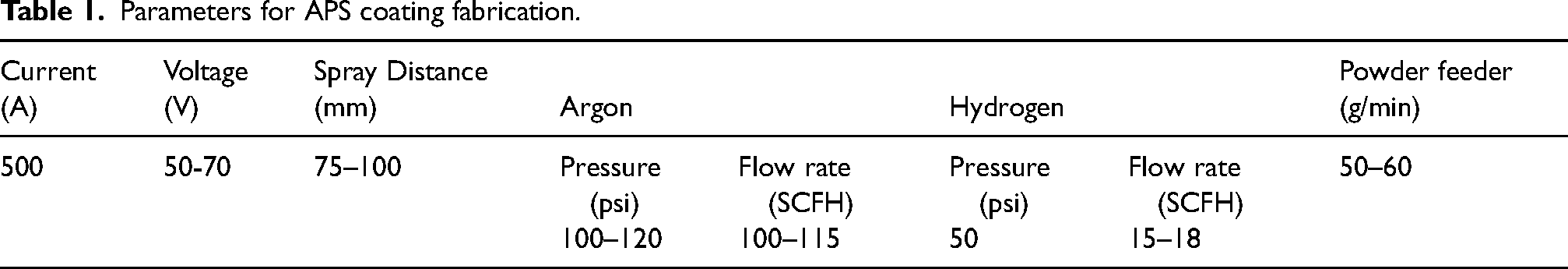
As-synthesized Y3NbO7 was deposited onto an Inconel-600 substrate using the plasma spraying (APS, Oerlikon Metco) to fabricate a TBC system. The surface of Inconel-600 was prepared through alumina grit blasting to achieve strong adhesion. The parameters for the coating deposition are provided in Table 1.
Parameters for APS coating fabrication.
Scanning Electron Microscopy (Zeiss Sigma) was performed on the coated sample to investigate its microstructure and splat structure. Additionally, XRD analysis was done to observe any probable decomposition of Y3NbO7 during the APS process.
For investigating thermal barrier and hot corrosion characteristics, cylindrical Y3NbO7 pellet samples were fabricated. These samples were fabricated using a hydraulic press and sintered at 1500°C for 6 h. The surface characteristics of the samples were analyzed using SEM imaging and X-ray diffraction was performed to identify any possible decomposition that might occur during the sintering process.
The thermal diffusivity of Y3NbO7 was determined by the Laser Flash Method (LFA, DLF-2, Waters) on a sample (φ10 mm×2 mm). Thermal conductivity (k) was then obtained using Equation 1:
The Klemens relation was employed to calculate the thermal conductivity, with adjustments made to account for the porosity in the sintered pellet.
18

The thermal expansion coefficient (CTE) was determined up to 1000°C with dilatometry technique. The measurement was performed on a cylindrical pellet of φ 10 mm × 30 mm dimensions. To examine the interaction of Y3NbO7 with thermally grown oxide (TGO), the as-prepared Y3NbO7 was blended with Aluminum Oxide (Al2O3) in equal molar amounts and was heated at 1200°C for 6 h. XRD was conducted to observe any probable reactions with Al2O3.
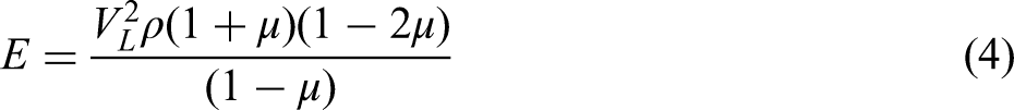
The ultrasonic velocities (both longitudinal and transverse) were obtained in a sample (φ10 mm×5 mm) with the transducers in pulse-echo configuration. These velocities were applied in Equations 3 and 4 to determine the elastic modulus.
19
An ultrasonic probe (M110-RM, 5 MHz) along with a thickness gauge (Olympus, 45MG) was used to obtain the longitudinal velocity. The transverse velocity was found using a shear probe (5 MHz) in conjunction with an oscilloscope (Tektronix, MSO44)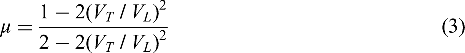
Vickers microhardness testing was performed on a Y3NbO7 sample (φ10 mm × 5 mm) with a Digital Microhardness Equipment (Matsuzawa, MMT-X) based on ASTM E-384 with a load of 1 kg for 15 s (HV1).
To assess the behavior of the as-deposited coating under thermal shock, a thermal cycling test was conducted. The samples were held isothermally at 1000°C for 30 min and then rapidly cooled to room temperature within 5 min using compressed air. This procedure was repeated for 48 identical cycles to monitor any significant spallation or delamination of the coating.
To simulate sulfur and vanadium contaminants, a Na2SO4 + V2O5 salt blend was used for the hot corrosion experiment. The eutectic composition of the binary phase diagram (32 wt% Na2SO4 + 68 wt% V2O5), 20 was selected to ensure the early formation (at 630°C) of molten salt during exposure. A salt load of 1 wt% of the pellet was applied evenly over the surface. These designed conditions—including a highly acidic species, a thicker corrosive layer, and the earlier formation of corrosive melt—were intended to expedite the hot corrosion process and yield measurable results in a shorter period. 21 The ratios of the salt mixture and the corrosion period used in the study do not precisely replicate the real conditions in TBC applications. Instead, they are meant to simulate high-temperature sulfate-vanadate corrosion conditions to evaluate the response of Y3NbO7.
Studies have shown that when exposed to elevated temperatures (∼1100°C), the evaporation of SO3 from the Na2SO4 + V2O5 melt (Equation 5) decreases the activity of V2O5, leading to a reduction in the hot corrosion attack of the mixture.22–24
The hot corrosion experiments were performed on Y3NbO7 pellets (φ10 mm × 5 mm) using salt melts of Na2SO4 + V2O5 mixture, pure V2O5 and pure Na2SO4 separately. The salt mixtures were prepared by thoroughly mixing the salts in deionized water. Each mixture was applied evenly (salt load of 30 mg/cm²) on the top surface of the samples using a glass rod, with careful attention to avoid from contacting the edges. The samples were then heated on a hot plate to evaporate any excess water and obtain adequate adhesion of the salt. The heating program for the corrosion experiment is illustrated in Figure 1. The heating and cooling rate for the heat treatment program were 5°C/min and 2.5°C/min respectively. The samples were subjected to five cycles of 6-h corrosion at 900°C, resulting in an aggregate heating period of 30 h. XRD analysis was executed to determine the corrosion products, and SEM-EDS was used to study the microstructural changes in the samples.
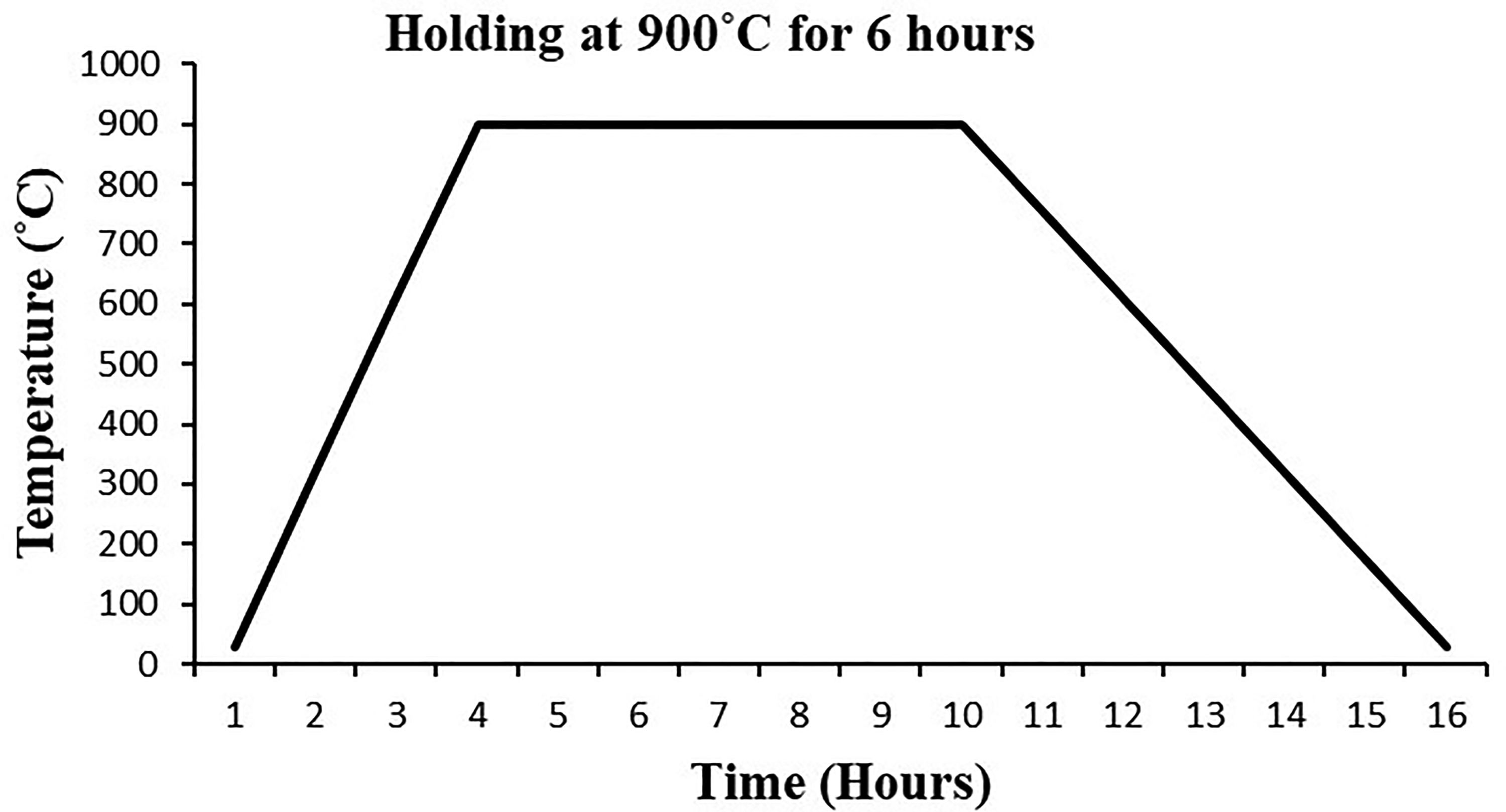
Heating program of hot corrosion test.
Results and discussion
The XRD pattern of the synthesized Y3NbO7 powder was very similar to the standard ICSD pattern 98-009-9881 (Figure 2), which corresponds to a defect fluorite structure with a cubic unit cell (Fm-3m). The powder had a crystallographic density of 5.25 g/cm³, and the lattice parameters, as determined by Rietveld refinement, were a = b = c = 5.254 Å. The lattice parameter value closely matches with that of ICSD 98-009-9881 pattern, which is 5.2450 Å. In crystal structure of Y3NbO7, Y and Nb atoms are randomly distributed in cationic positions in a 3:1 ratio, with 1/8 of the oxygen sites unoccupied to ensure chemical balance. While this structure resembles that of conventional yttria-stabilized zirconia, Y3NbO7 features anion deficiency in 1/8 of the sites, compared to 1/50 in 7YSZ. This difference could significantly affect important TBC properties, such as thermal conductivity.
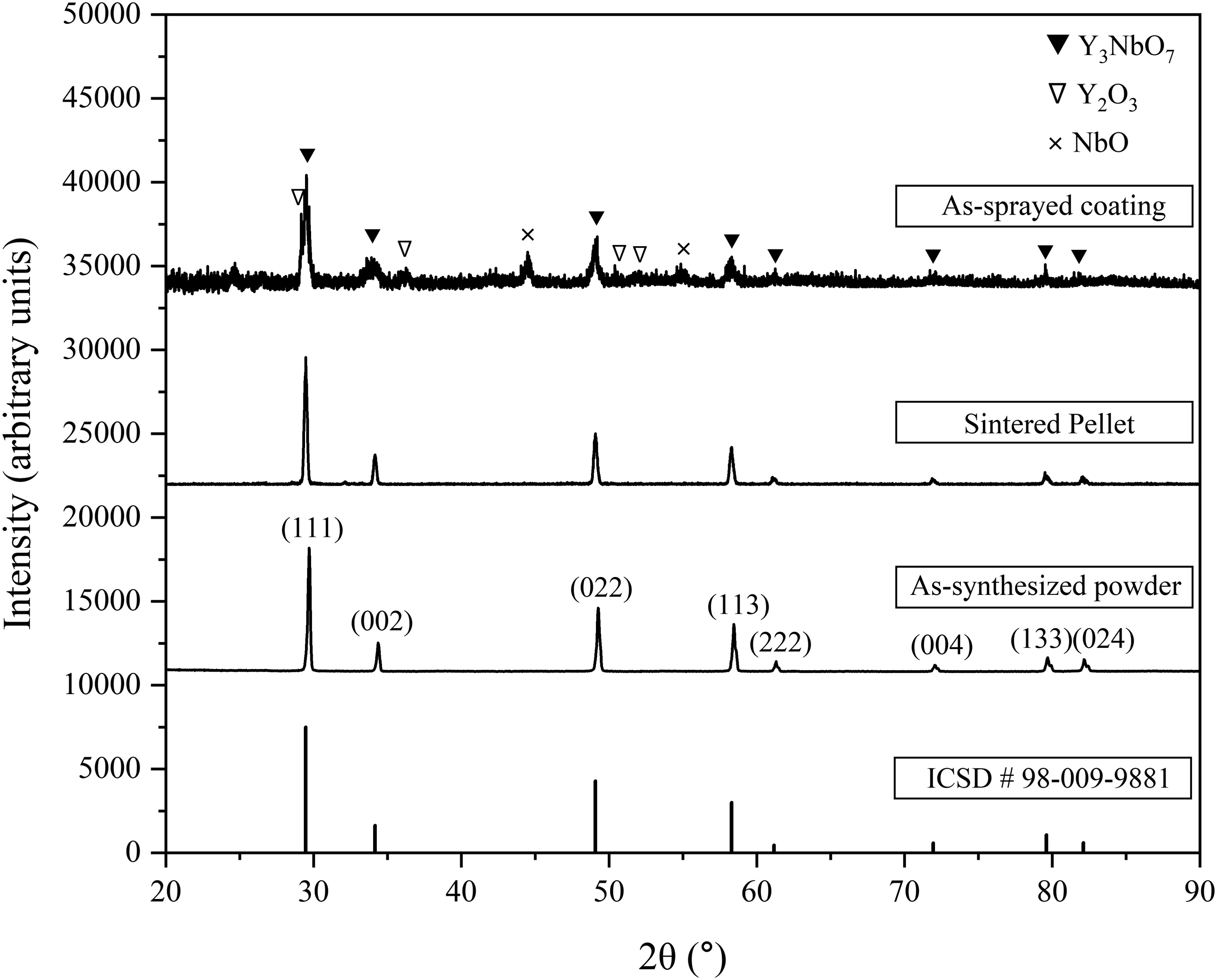
XRD patterns: ICSD 98-009-9881, prepared powder, pellet and coating.
The XRD results from both the sintered pellet and coating sample (Figure 2) closely resembled that of the Y3NbO7 powder. There weren’t any discernible peaks in the pellet pattern other than those corresponding Y3NbO7 which suggested that Y3NbO7 did not undergo any kind of decomposition during sintering. However, the coating pattern exhibited broader peaks, likely due to the rapid cooling during the plasma spraying. The coating pattern included extra peaks not seen in the powder pattern, which have been identified as Y2O3 (ICSD 98-010-4015) and NbO (ICSD 98-006-9409). This indicates that a minor decomposition of Y3NbO7 occurred during deposition. This is likely due to the significant difference in vapor pressures of Y2O3 (10−6 to 10−5 Pa at 2000°C) and Nb2O5 (10−5 to 10−2 Pa at 2000°C) and dissociation of Nb2O5 at elevated temperatures.25,26 The accompanied variation in Y3NbO7 stoichiometry may affect the performance of the TBC, for which the composition of feedstock needs to be monitored to obtain stochiometric Y3NbO7 coating, particularly during coating deposition using methods such as EB-PVD.
The SEM image of the prepared Y3NbO7 powder, shown in Figure 3(a), reveals an irregular morphology with fairly consistent size distribution, likely resulting from ball milling. Figure 3(b) shows the EDS analysis of the prepared powder, indicating a composition that closely aligns with the theoretical stoichiometric values. The A : B cationic ratio obtained from EDS (3.13:1) aligns with the formula of the Y3NbO7 compound. Additionally, the DLS (Nano Plus, Micromeritics) method determined the average particle size of the Y3NbO7 sample to be 7.2 μm, with the particle size distribution provided in Table 2.
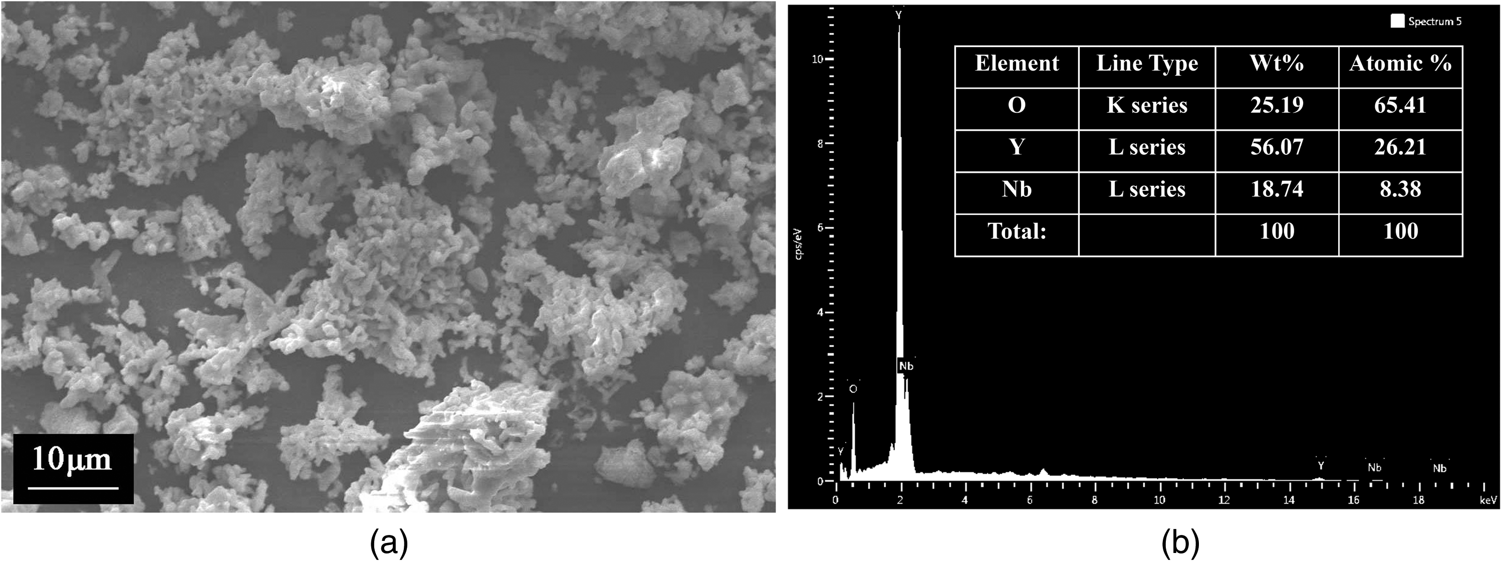
(a) SEM micrograph and (b) EDS results of Y3NbO7 powder.
Particle size distribution of prepared Y3NbO7.
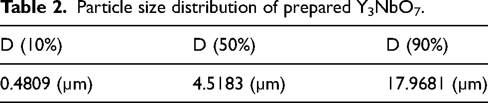
Figure 4(a) and (b) display surface micrographs of the pellet and the coating. The SEM image of the pellet shows grains with a consistent size distribution, averaging around 2 µm. The pellet also features several open micropores. On the other hand, the coating image reveals both open pores and cracks, which are typical for TBCs. The coating consists of fully molten and partially molten splats, along with some unmolten particles. The cross-sectional SEM of the coated sample (Figure 4(c)) depicts good adhesion of the bond coat (thickness ∼120μm) with base material. However, the Y3NbO7 topcoat is comparatively thin with a rough surface (thickness ∼60μm), since the powder lacks the free-flowing, spherical morphology that promotes easier melting and deposition.
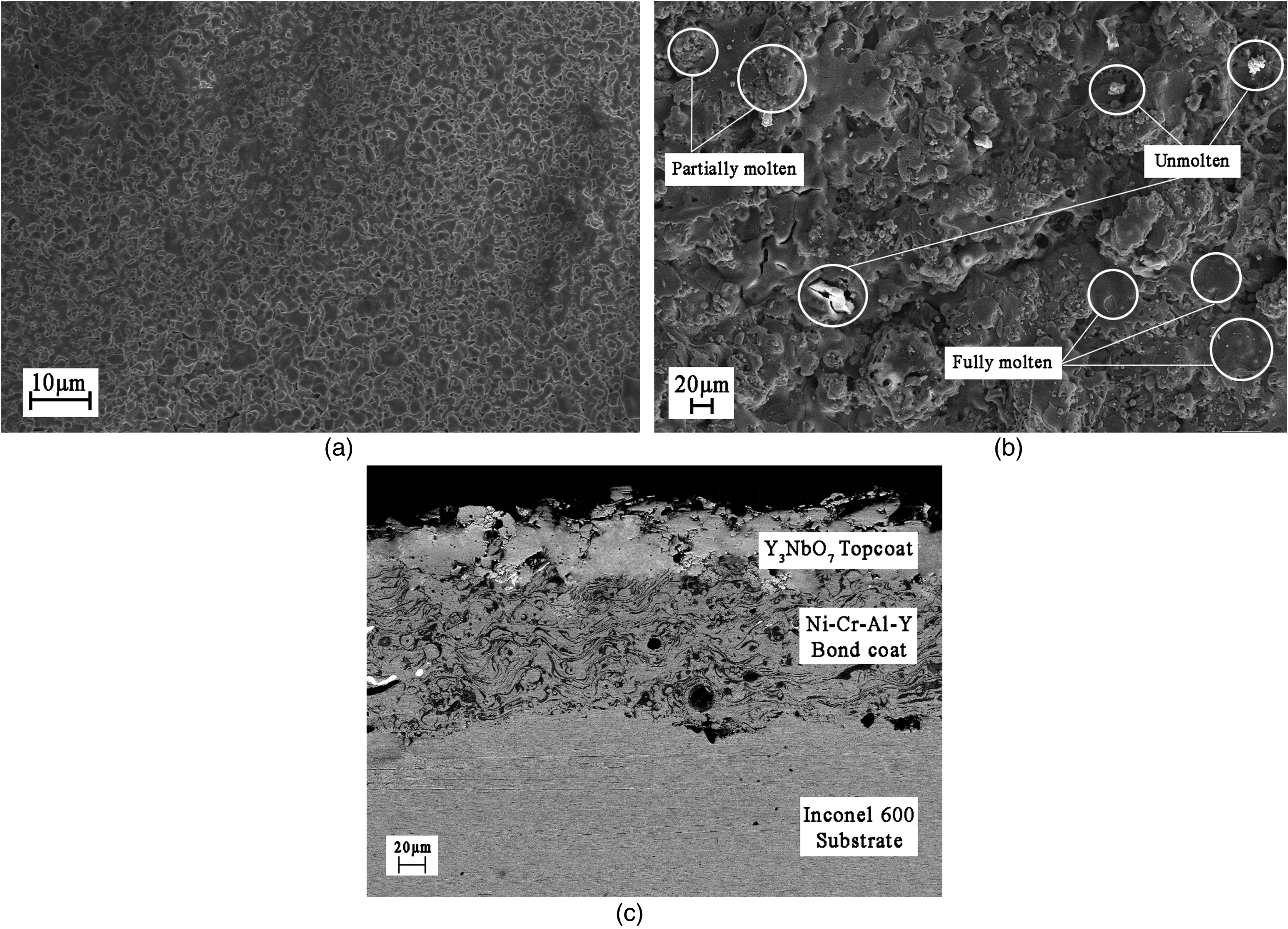
Surface micrograph of the (a) Y3NbO7 pellet (b) Y3NbO7 coated sample; (c) cross-sectional micrograph of the coating.
Thermal diffusivity of Y3NbO7 was measured from 30°C to 1200°C at 200°C intervals which decreased from 0.5089 mm2 s−1 at 31.7°C to 0.4593 mm2 s−1 at 1200.5°C (Figure 5(a)). Heat capacities at these temperatures were calculated using the Neumann-Kopp rule (Figure 5(b)). 27 The density of the sample used for the measurement was 5.03 g cm−3 (95.8% of the theoretical value). Thermal conductivity was obtained using Equation 1, and the value for the 100% dense material was obtained using Equation 2 by correcting the error due to porosity. The values are plotted in Figure 5(a), demonstrating an initial decrease from 2.28 W m−1 K−1 (30°C) to 1.77 W m−1 K−1 (600°C) further increase to 2.68 W m−1 K−1 (1200°C)
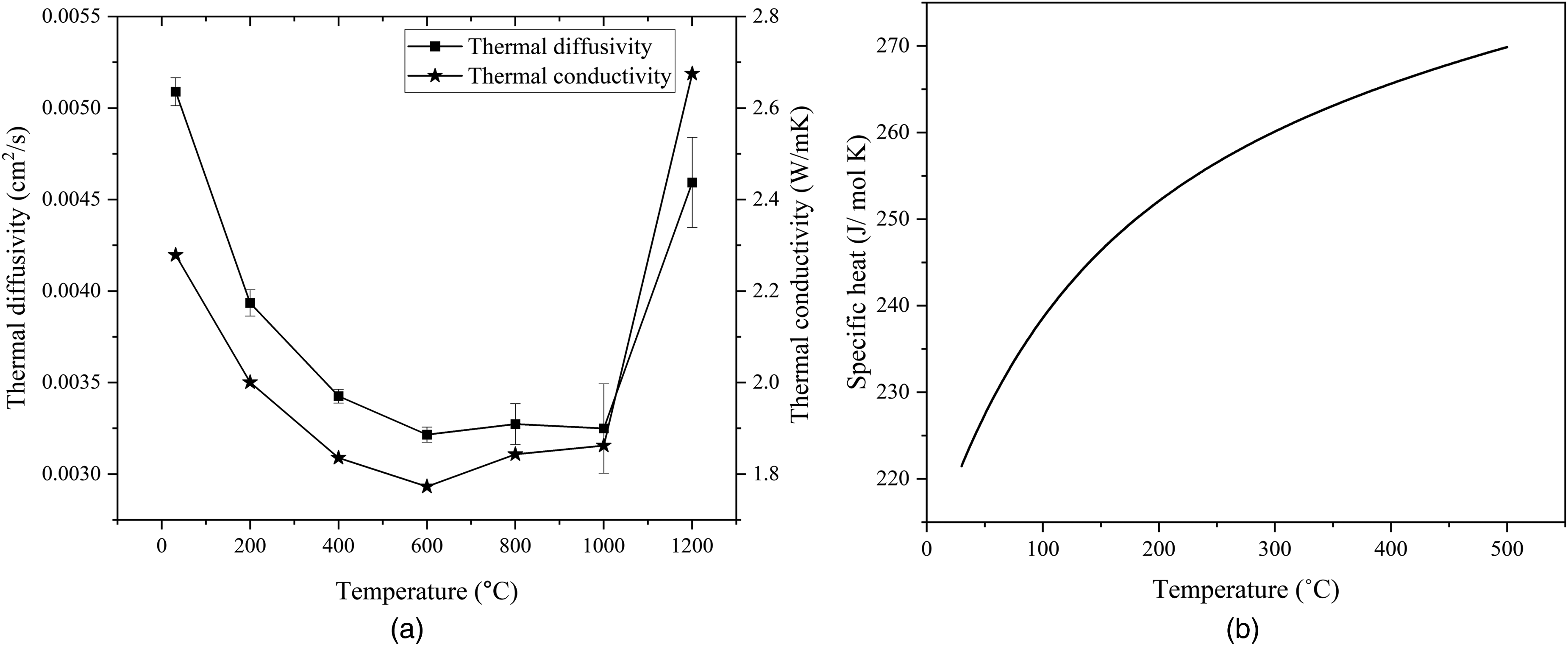
(a) Thermal diffusivity and conductivity (b) calculated specific heat of Y3NbO7. 27
The thermal conductivity values of Y3NbO7 were comparable to those of YSZ (2.2–2.9 W m−1 K−1). Unlike common binary oxides used in TBCs, which typically show a decrease in thermal conductivity with temperature (following a 1/T dependence), the thermal conductivity of Y3NbO7 showed slight increase with temperature after initial decrease from room temperature value. This unusual behavior is amorphous-like and characteristic of lanthanide niobates. The lower thermal conductivity of lanthanide niobates, despite being simple binary oxides, is often attributed to substantial chemical variability caused by disparity in cationic charge and bond length. 4 The difference in atomic radii and ionic charges between Y3+ (1.019 Å) and Nb5+ (0.74 Å) leads to the disparity in bond lengths and strengths of Y-O and Nb-O, aligning with this interpretation.
An important factor influencing the performance of TBCs at high temperatures is the coefficient of thermal expansion (CTE) of the topcoat. Ideally, the CTE of the topcoat should align with that of the metallic superalloy to reduce stresses caused by differing thermal expansion. The density of the sample used for the measurement was 5.055 g cm−3 (96.2% of theoretical density). Y3NbO7 exhibited a linear thermal expansion, as illustrated in Figure 6(a). The coefficient of thermal expansion (TEC) for Y3NbO7 rose from 2.2 × 10⁻⁶ K−1 at room temperature (40°C) to 10.84 × 10⁻⁶ K−1 at 670°C, before slightly decreasing to 10.25 × 10⁻⁶ K−1 at 1000°C, as depicted in Figure 6(b). These values for TEC were comparable to that of YSZ, remaining fairly constant throughout most of the measured temperature range (ranging from 10 × 10−6 K−1 at 310°C to 10.25 × 10⁻⁶ K−1 at 1000°C). Y3NbO7 possesses a defect fluorite structure with unoccupied anionic positions that allows for greater atomic displacement under thermal stress than more rigid structures. Furthermore, the bonding in Y3NbO7, characterized by both ionic and covalent components, promotes increased atomic mobility, leading to a higher thermal expansion coefficient.
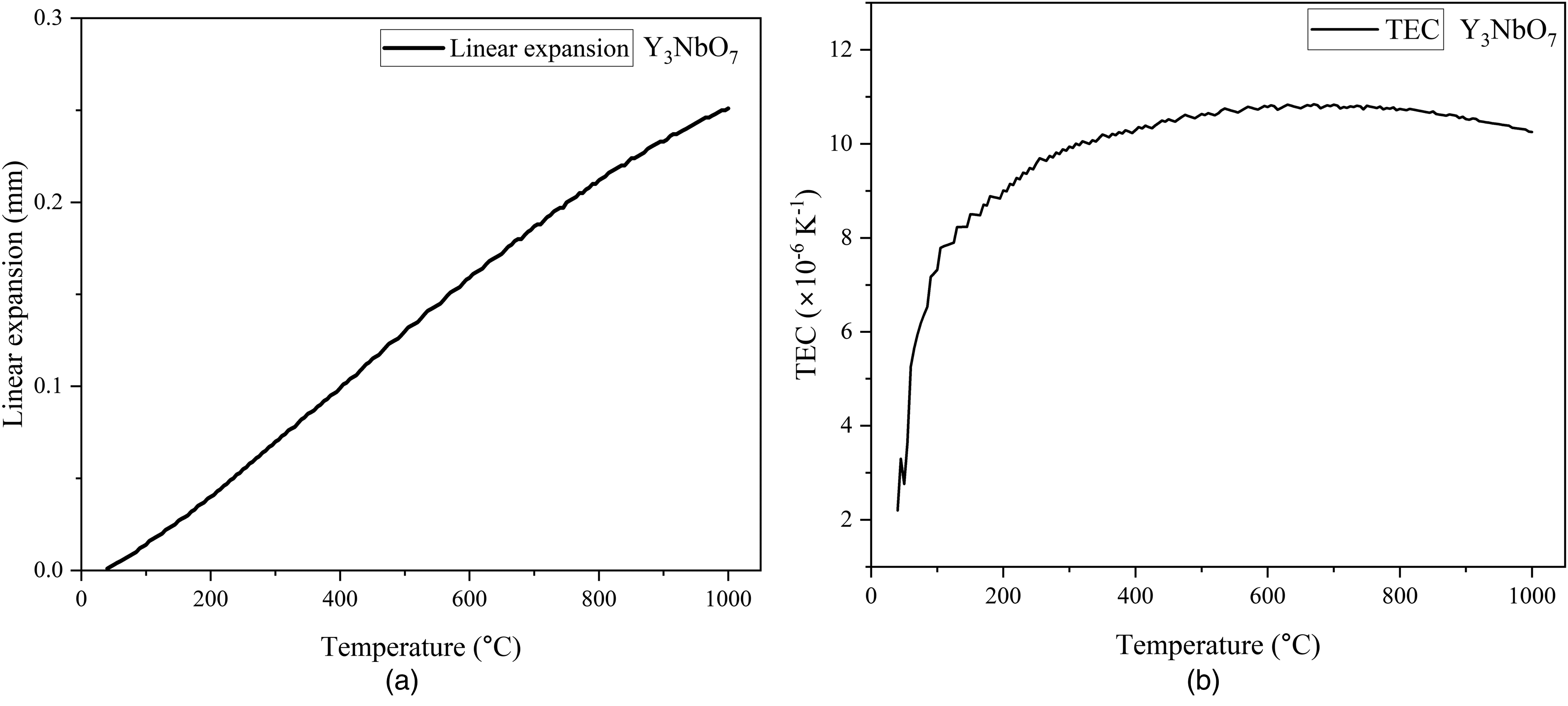
(a) Linear expansion and (b) CTE of Y3NbO7.
The elastic modulus of Y3NbO7 was obtained by finding the ultrasonic wave velocities using the pulse-echo method. The ultrasonic wave velocities, along with the calculated elastic modulus (Equations 3 and 4), are presented in Table 3.
Ultrasonic velocities and elastic constant of Y3NbO7.
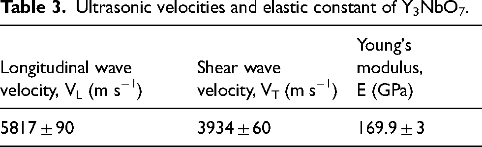
The average microhardness of the Y3NbO7, measured using Vickers micro indentation (ASTM E-384), was found to be 7.79 GPa (794 HV1).
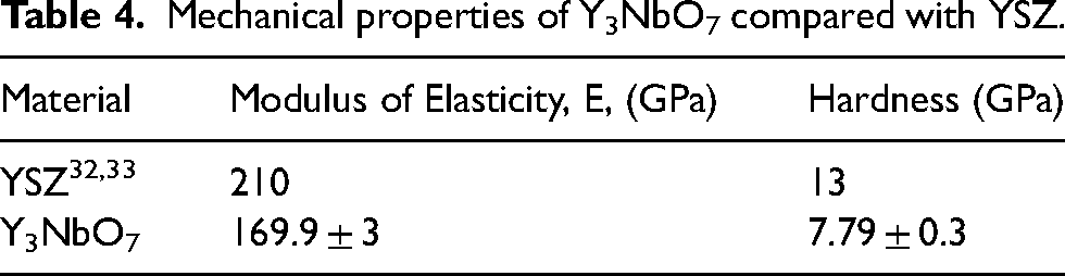
The mechanical properties of Y3NbO7 were found to be less than that of conventional YSZ. 28 Table 4 provides a comparison of the mechanical properties prepared Y3NbO7 with that of YSZ. The lower hardness value is suggestive of reduced coating performance in erosive conditions. However, it is promising while compared to the alternative materials presently considered for TBC application.29–31 The lower elastic modulus indicates improved strain compliance, implying enhanced performance during thermal cycling. This indicates that a TBC topcoat made of Y3NbO7 may exhibit better performance under thermal cycling conditions.
Mechanical properties of Y3NbO7 compared with YSZ.
Chemical compatibility with the TGO layer is crucial when evaluating the suitability of a material as a topcoat. To maintain the coating's integrity at high temperatures, it is essential that it remains stable and non-reactive with the thermally grown oxide (TGO). The TGO, mainly consisting of aluminium oxide (Al2O3), develops from the oxidation of aluminium in the bond coat as oxygen diffuses through the topcoat.34–37 The XRD pattern of Y3NbO7 - Al2O3 mixture after heating (Figure 7) revealed no additional peaks except those corresponding to Y3NbO7 (ICSD 98-009-9881) and Al2O3 (ICSD 98-005-3283). Thus, it can be inferred that the Y3NbO7 topcoat is expected to remain unreactive with TGO during high-temperature exposure.
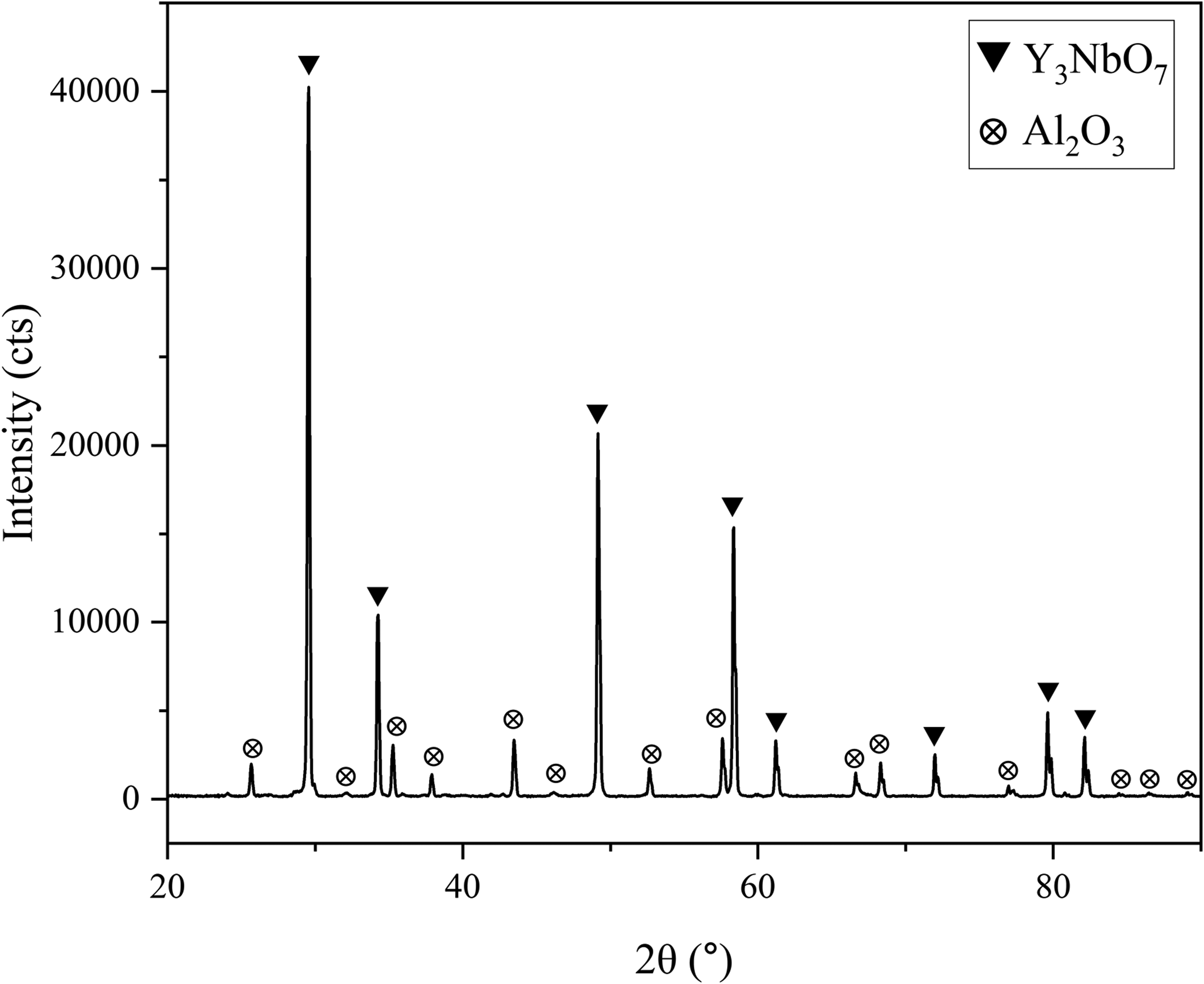
XRD pattern of Y3NbO7 – Al2O3 mixture after 6 h heating at 1200°C.
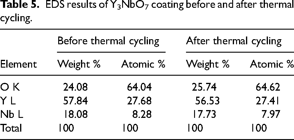
To assess the durability of this TBC system, a thermal cycling test was performed on the as-deposited Y3NbO7 coated sample for 48 cycles. The coating remained intact without any notable indication of cracking or spallation on the surface. In the thermal cycling experiment, the failure of the TBC often begins at the beveled edge, where the coating is subjected to tension. As illustrated in Figure 8(a) and (b), there was no evidence of significant spallation at any of the edges, and no color change was observed in the sample during exposure. A comparison of the EDS results from the sample before and after thermal cycling (Table 5) indicates that the stoichiometry of the coating remained consistent throughout the experiment. This finding suggests that the Y3NbO7 coating can maintain its integrity over multiple heating and cooling cycles compared to other alternative TBC materials currently being investigated. 38 To examine the coating microstructure before and after thermal cycling, SEM-EDS analysis was conducted. The coating appears slightly denser (Figure 9(a)) compared to its state before thermal cycling (Figure 4(b)), and the porosity level has significantly decreased, as evidenced by the micrographs in Figures 4(b) and 9(a). This may be attributed to the sintering of the coating during isothermal exposure, leading to more uniform grain sizes after thermal cycling. However, the cross-sectional micrographs depicting the splat morphology before (Figure 9(c)) and after thermal cycling (Figure 9(b)) show a greater number of microcracks. One fundamental reason for these cracks is the thermal stresses that arise during thermal cycling.
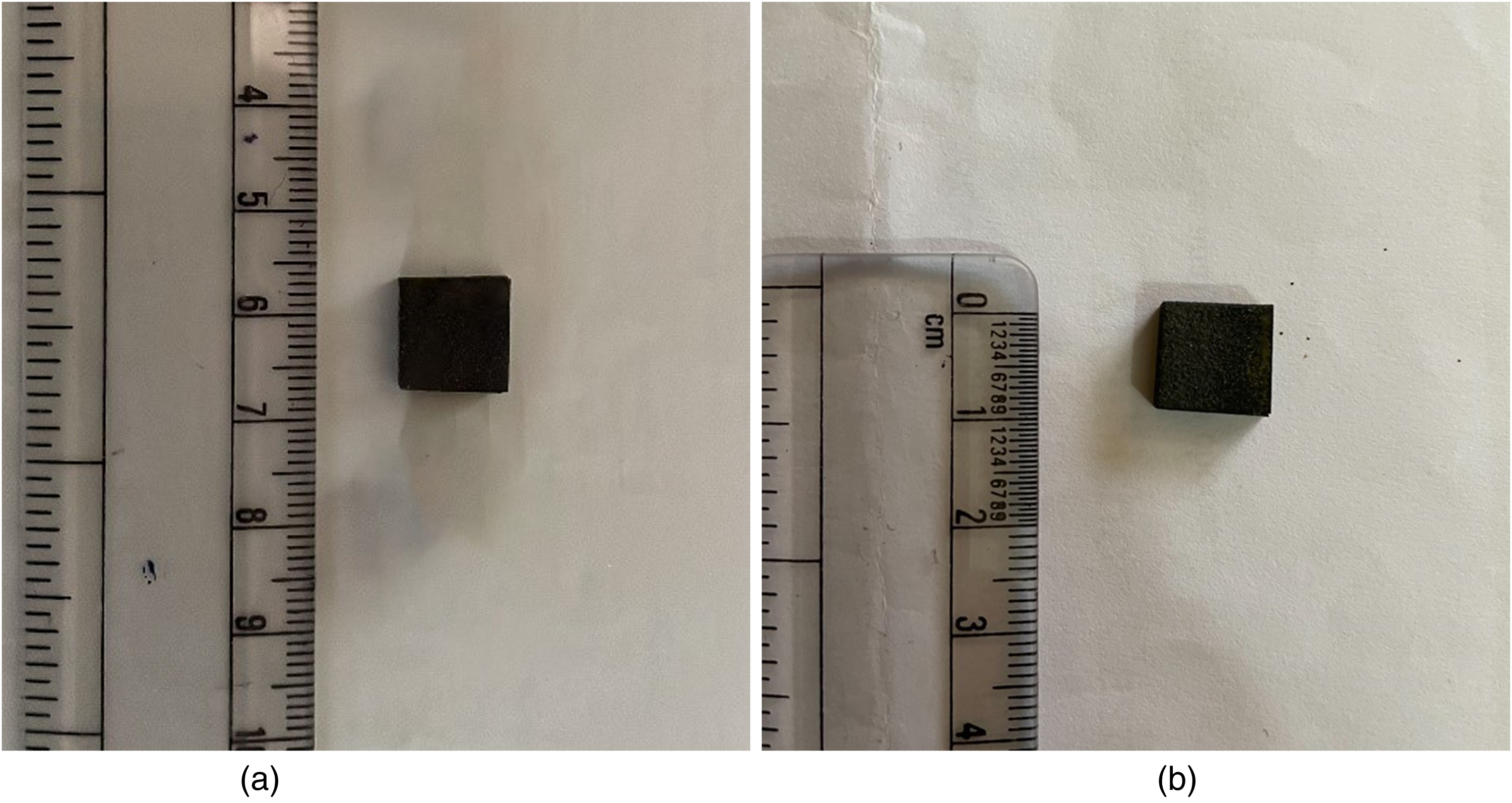
Y3NbO7 coated sample (a) before and (b) after thermal cycling test.
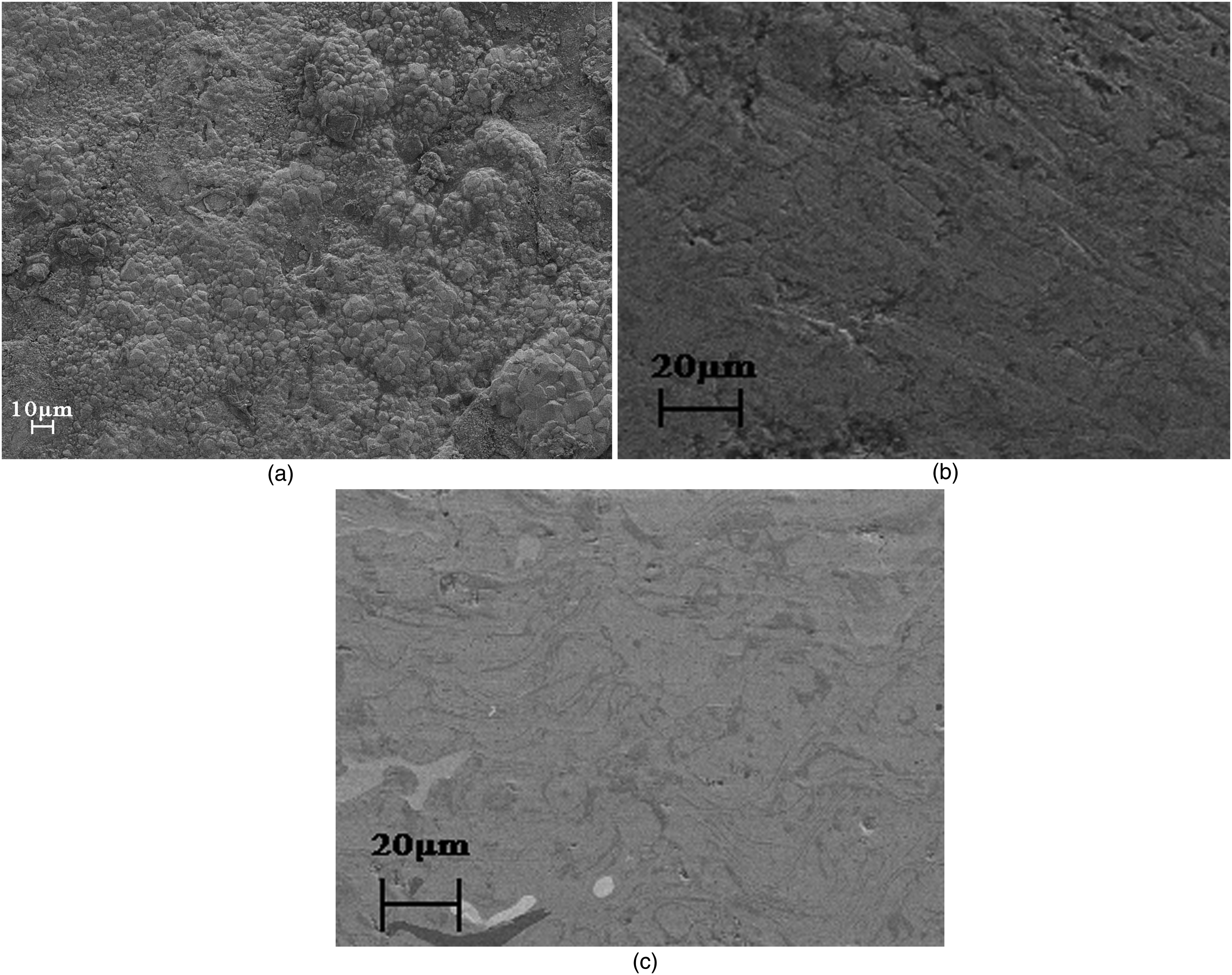
SEM image of Y3NbO7 coating: (a) surface and (b) cross-sectional splat morphology after thermal cycling; (c) cross-sectional splat morphology before thermal cycling.
EDS results of Y3NbO7 coating before and after thermal cycling.
The surfaces of the samples exposed to in a Na2SO4 + V2O5 corrosive mixture showed notable color changes, turning predominantly grey. These color shifts indicate corrosive reactions. SEM micrographs of the pellet surfaces after the experiment are shown in Figure 10(a) and (b). The micrographs display altered particle morphologies, suggesting significant corrosive activity. The ceramic pellet prior to exposure (Figure 4(a)) exhibited a relatively dense microstructure with a uniform grain size distribution. However, high-temperature exposure to corrosive salt led to significant disintegration of the sample surface, as shown in Figure 10. The corroded samples revealed the presence of rod/plate-like particles with varying thicknesses, as seen in Figure 10(b).
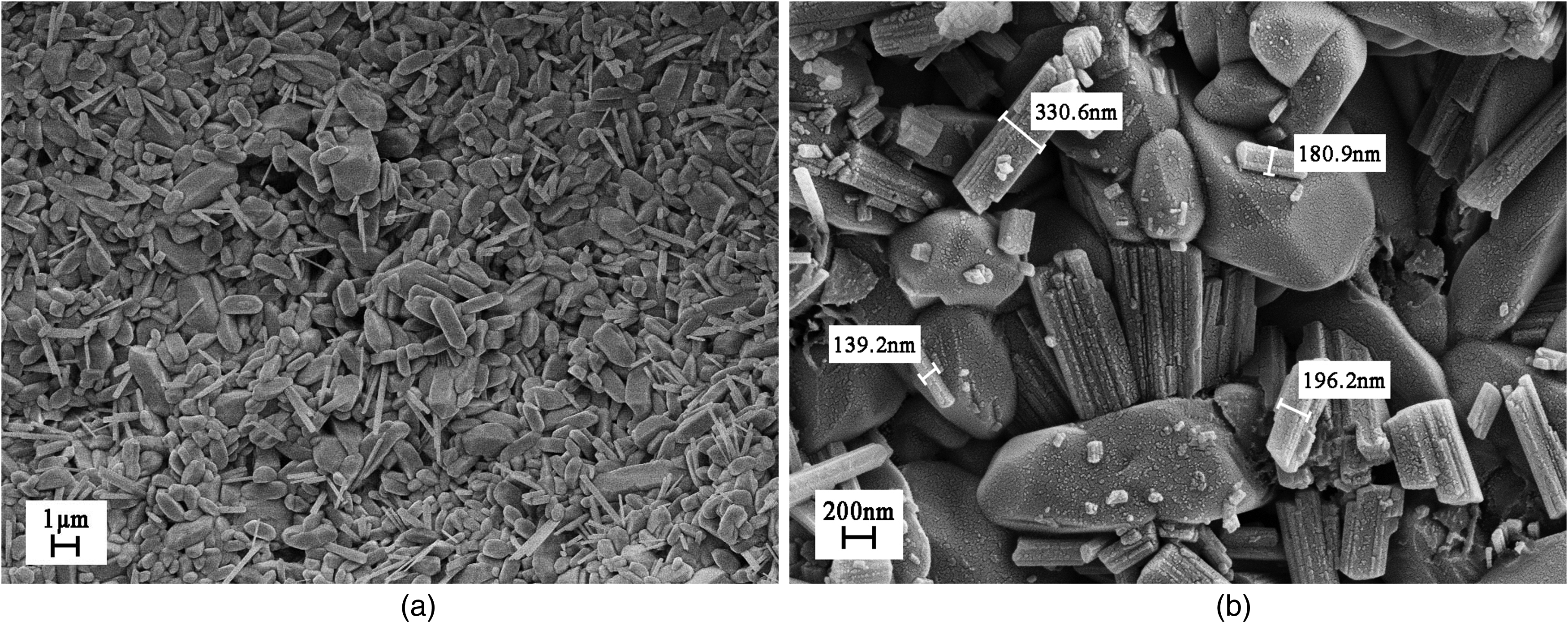
SEM micrograph of Na2SO4 + V2O5 exposed Y3NbO7 at (a) 10KX (b) 50KX.
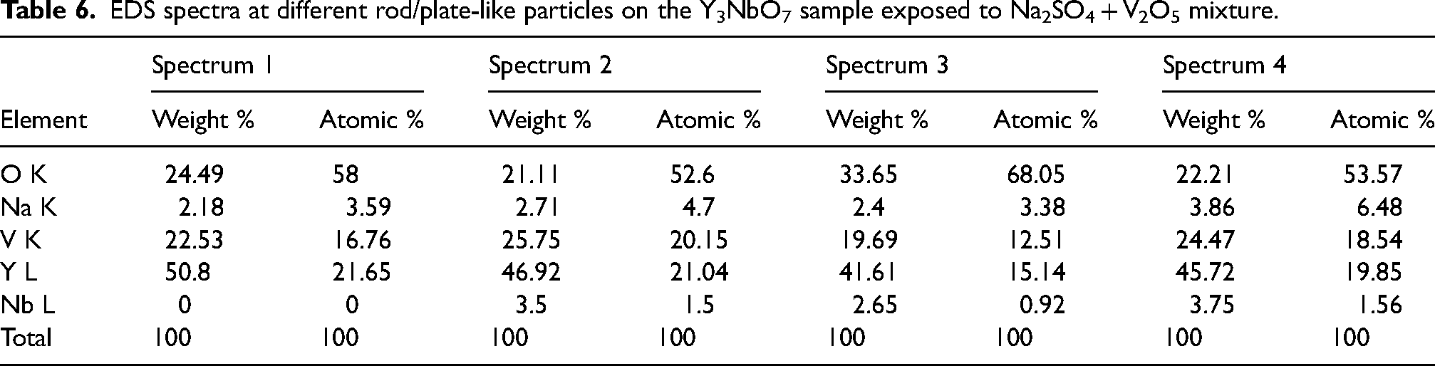
SEM-EDS analysis indicated that the particles primarily consist of Y, V, and O elements (Table 6). XRD results (Figure 11(c)) confirmed that the rod/plate-like particles are mainly YVO4 (ICSD 98-003-5198). The XRD patterns also showed minor peaks corresponding to Y2V2O7 (ICSD 98-011-3329), YNbO4 (ICSD 98-007-2062), and NaNbO3 (ICSD 98-007-1460). The Y:V atomic ratio in some EDS spectra (spectrum 2) matched that of Y2V2O7, supporting its presence. However, the presence of YNbO4 and NaNbO3 particles could not be confirmed by EDS, likely due to their low concentrations as suggested by the XRD data. Additionally, the detection of small amounts of Na and Nb within YVO4 and Y2V2O7 particles in the EDS results implies that the hot corrosion process likely involved dissolution and reprecipitation. Thus, the main corrosion product of Y3NbO7 in a 32 wt% Na2SO4 + 68 wt% V2O5 mixture at 900°C is inferred to be YVO4.
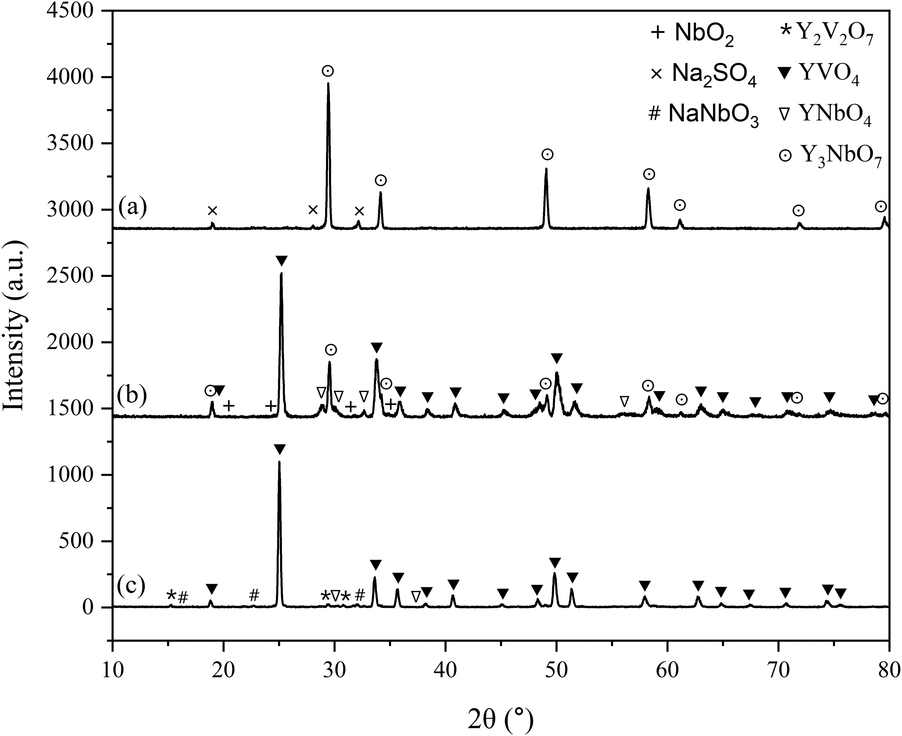
XRD pattern of the Y3NbO7 pellets after 30 h of high-temperature exposure to (a) Na2SO4 (b) V2O5 (c) Na2SO4 + V2O5 salt mixture.
EDS spectra at different rod/plate-like particles on the Y3NbO7 sample exposed to Na2SO4 + V2O5 mixture.
Figures 11(a) and (b) illustrate the XRD results of Y3NbO7 samples after 30 h exposure to pure Na2SO4 at 900°C and pure V2O5 salt melts at 900°C, respectively. For the Na2SO4 corrosion test, the XRD pattern primarily displayed sharp peaks corresponding to Y3NbO7 (ICSD 98-009-9881) and minor peaks of Na2SO4 (ICSD 98-001-2491). This indicates that Y3NbO7 remained practically unreactive in pure Na2SO4 environment. In contrast, the XRD pattern for the pellet corroded in V2O5 exhibited sharp peaks of YVO4 (ICSD 98-000-7818) and Y3NbO7, along with minor peaks of YNbO4 (ICSD 98-007-2062) and NbO2 (ICSD 98-001-0013).
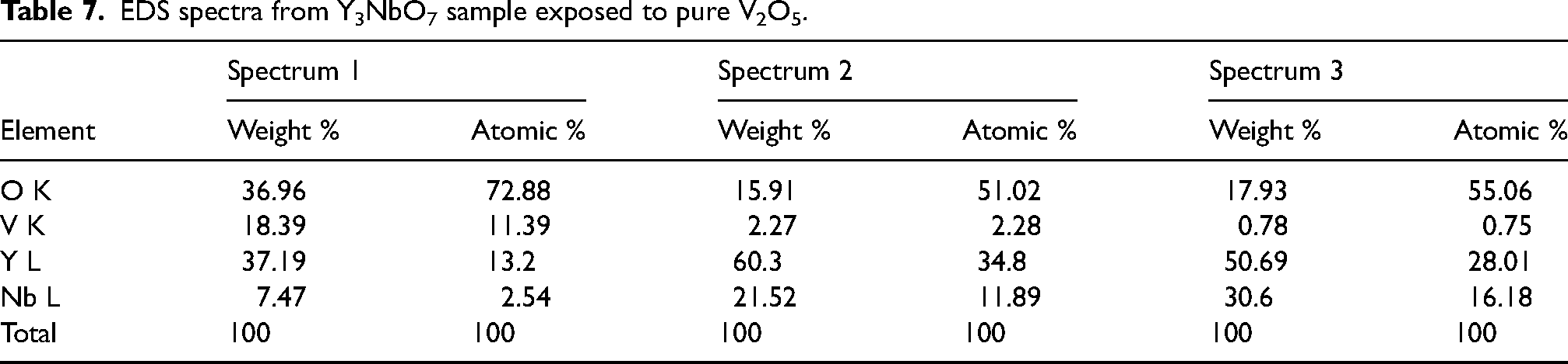
Table 7 presents the EDS spectra from the V2O5 hot corrosion sample. The EDS results confirm the XRD findings, showing the presence of YVO4 (spectrum 1), Y3NbO7 (spectrum 2), and YNbO4 (spectrum 3). The Y:V and Y:Nb molar ratios observed in the respective particles match closely with theoretical values. However, NbO2 particles were not detected by EDS, likely due to its low concentration. Additionally, the presence of minor quantities of Nb in YVO4 and V in both Y3NbO7 and YNbO4 suggests that the hot corrosion process involved dissolution and reprecipitation mechanisms.
EDS spectra from Y3NbO7 sample exposed to pure V2O5.
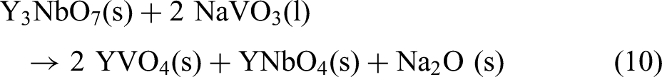
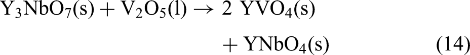
The corrosive reactions during the tests can be understood through Lewis acid-base theory. Y3NbO7 is a complex oxide composed of Y2O3 and Nb2O5 in 3:1 ratio. Under corrosive conditions, it is expected to decompose into component oxides because of the acidic leaching of Y³+ ions from Y3NbO7 (Equation 7).
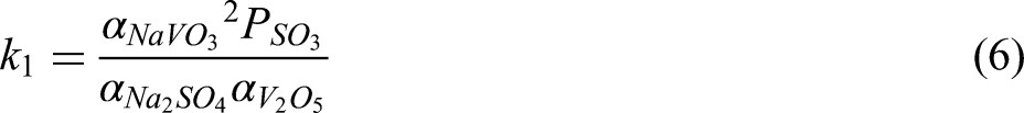
Given the lack of studies on the Y2O3-NaVO3 system compared to the extensively reported Y2O3 -V2O5 system, it is plausible to forecast the reactions between Y3NbO7 and NaVO3 based on the Y2O3-V2O5 phase diagram.
41
In the Y2O3 -V2O5 system, two major compounds, YVO4 and Y2V2O7, are formed depending on the Y2O3:V2O5 ratio. Therefore, it can be concluded that the reaction between Y2O3 and NaVO3 starts at 630°C (Equation 8), leading to the formation of YVO4, as indicated by the XRD results (Figure 11).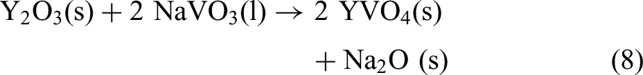

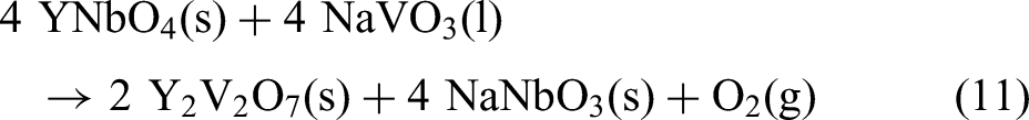
A comparison of the hot corrosion tests conducted with pure Na2SO4 and pure V2O5 versus the 32 wt% Na2SO4 + 68 wt% V2O5 mixture shows notable differences in the activity of V2O5. Figure 11(a) illustrates that exposure to Na2SO4 produced prominent peaks for Y3NbO7 and minor peaks for Na2SO4, suggesting that Na2SO4 by itself did not cause degradation of Y3NbO7. In contrast, the V2O5-exposed sample displayed sharp peaks for both YVO4 and Y3NbO7 (Figure 11(b)), suggesting that the acidic action of V2O5 was less severe compared to the 32 wt% Na2SO4 + 68 wt% V2O5 mixture. The corrosion pattern for the mixture sample, which showed no peaks for Y3NbO7 (Figure 11(c)), indicates complete disintegration of Y3NbO7 at the exposed surface. This demonstrates that the combined effect of V2O5 and Na2SO4 was much more corrosive than V2O5 alone. Additionally, the presence of NaVO3 resulted in enhanced atomic mobility, which accelerated the corrosion phenomena.
The acidic leaching Y2O3 by pure V2O5 could be described as follows: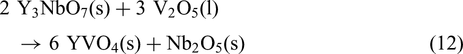

Conclusions
Single-phase Y3NbO7 powder was prepared through a solid-state method, utilizing Y2O3 and Nb2O5 as precursors. Pellet samples, prepared through pressureless sintering were used for hot corrosion experiments and thermal property measurements. A plasma sprayed TBC architecture was fabricated using the prepared powder to illustrate the viability of Y3NbO7 for coating deposition.
The thermal properties of Y3NbO7 indicate its potential for use as a TBC material. Its thermal conductivity is lower than that of YSZ, and the thermal expansion coefficient values are appropriate for TBC applications. Y3NbO7 was unreactive with Al2O3, indicating good TGO compatibility during service. The thermal cycling test demonstrated that the as-deposited Y3NbO7 retained its original stoichiometry and coating integrity for a minimum of 48 cycles. Out of the measured mechanical properties lower elastic modulus was found to be beneficial for TBC applications, suggestive of improved thermal cycling performance. However, the lower hardness compared to YSZ indicates potentially poor coating response under erosive conditions. Y3NbO7 experienced aggressive corrosion in 32 wt% Na2SO4 + 68 wt% V2O5 melt, with Y3+ ions leaching out and reacting with NaVO3 to form YVO4. In comparison, corrosion in pure V2O5 was less severe, and pure Na2SO4 did not significantly destabilize Y3NbO7. Combining Na2SO4 with V2O5 increased the activity of V2O5 by producing NaVO3 and enhanced corrosion process. None of the corrosion tests provided evidence of significant amounts of Nb-V-O compounds, confirming that the corrosion process followed the Lewis acid-base principle.
Footnotes
Declaration of conflicting interests
The authors declared no potential conflicts of interest with respect to the research, authorship, and/or publication of this article.
Funding
The authors received no financial support for the research, authorship, and/or publication of this article.