
Abstract
Development of micro-abrasive tools enables manufacturing of micro-parts and micro-features for various applications. However, the main challenge is to deposit a highly adherent abrasive layer surrounding a precision micro-substrate. The present work involved fabrication of micro-abrasive tools consisting of an electroless Ni-P-diamond abrasive layer surrounding a WC-Co cylindrical tip of diameter 100 μm and length 500 μm. The effect of diamond grit concentration and ultrasonic agitation on the structure, chemical composition, microhardness, scratch hardness, and scratch adhesion of the abrasive layers were studied. An increase in grit concentration in the electroless bath, in the range of 0.5 to 1.5 g/l, led to the incorporation of a higher quantity of abrasives into the deposited Ni-P matrix. The grits were more uniformly distributed when subjected to ultrasonic agitation prior to their addition to the bath. However, towards higher grit concentration of 1.5 g/l, ultrasonic agitation was found to be ineffective in breaking the diamond clusters. The tools fabricated without ultrasonication exhibited some ‘Ni-void’ regions where diamond grits got accumulated, leaving little room for Ni deposition. Microhardness and scratch hardness of the tools scaled with grit content in the abrasive layers as well as with ultrasonication. In progressive-load scratch tests, localized removal and ploughing of the abrasive layer were observed at low diamond grit concentration of 0.5 g/l. However, abrasive layers synthesized with higher grit concentration and ultrasonication were found to be well adherent with no failure till a normal load of 32 N in the scratch test.
Keywords
Introduction
The demand for micro-parts and structures are increasing steadily in different sectors like chemical plants, automobiles, aerospace, biotechnology, tooling, etc.1–5 This is owing to the fact that such structures enable micro-scale mixing in microfluidic devices.6,7 micro-scale motions in micro-electro mechanical systems (MEMS),8,9 tailored surface contact in biomedical1,10,11 and tribological applications, etc.12,13 While lithography, electroforming, and molding (LIGA) technology is effective for bulk production of micro-features, it requires high capital investment and is specifically suitable for polymers. 14 Laser micromachining is also a popular choice for the fabrication of micro-features. However, it suffers from heat-affected zone (HAZ), thermal residual stresses, and undesirable and unpredictable changes in the microstructure of work materials due to heat input. 15 Such heat-induced defects may lead to crack propagation and hence may be extremely detrimental, particularly for brittle workpieces like silicon16,17 and quartz. 18 Tapering of the micro-holes or micro-channels is another serious issue. 19 Moreover, secondary processing may be required to remove the recast layers in precision products. 20 Technologies like micro-electrical discharge machining (micro-EDM) and micro-electrochemical machining (micro-ECM) also suffer from limitations while processing polymeric and ceramic materials.
Micro-grinding, on the other hand, is a mechanical micro-machining technique in which material removal is accomplished by interaction of the workpiece with the hard, abrasive grains distributed along the periphery of a fast-rotating micro-tool. 21 The micro-grinding process has been adapted for manufacturing micro-features with high aspect ratios in hard and brittle materials.1,22 Micro-grinding can also be employed for further finishing of features produced through other micro-fabrication processes. However, the challenge lies in fabricating a high-precision tool substrate and depositing a well-adherent abrasive layer containing diamond/cubic boron nitride (cBN) grits on the tool periphery.
Park et al. 23 reported on the fabrication of Ni-P-diamond micro-abrasive tools through an electroless process. In the composite plating bath, the diamond particles collided and settled on the substrate and subsequently got encapsulated with the Ni-P bond. The continuation of the process resulted in the deposition of a multilayer Ni-P-diamond abrasive layer. After the deposition of the composite layer of desired thickness, only the Ni-P bond synthesis continued to provide further anchorage to the protruded diamond grits. However, the Ni-P bond deposition is also terminated after some duration, leaving some portion of the grits exposed, to enable micro-machining action. It was observed that electroless bath deposition conditions like composite plating duration, embedding duration, bath stirring speed, and substrate rotation speed significantly influenced the structure and performance of the micro-tools. The study also revealed that larger diamond grits (5–10 μm) resulted in higher tool life while machining micro-slots in silicon. Arrabiyeh et al. 24 also acknowledged the important role of different bath conditions, like reducing agent concentration, bath pH, and bath stabilizer, in determining the structure and properties of micro-tools. Particularly, the role of bath stabilizer was found to be critical, and approximately 0.4 g/l concentration resulted in a high deposition rate of Ni-P and a smooth surface. It was also observed that high substrate rotation speeds beyond 9 rpm led to a decline in grit distribution and surface quality of the tools. While larger diamond grits led to higher tool life, the role of grit size was found to be less significant in determining the ground surface quality. 25 It was also observed by Zhou et al. 26 that a low substrate rotation speed of 3 rpm yielded a uniform diamond grit distribution during electroless deposition of the Ni-P-diamond abrasive layer. The grit distribution affected the chip-loading pattern, which, in turn, significantly affected the life of the tool.
One of the prime concerns during the development of micro-abrasive tools is maintaining the uniform placement of diamond/cBN grits on the substrate surface. This shall prevent intermittent tool-workpiece contact, thereby reducing tool chatter and fracture of the delicate micro-tip during high-speed tool rotation. Further, the size of the chip pockets shall also be controlled by grit placement, which in turn shall influence tool performance. 27 Sorkhabi and Eshaghi 28 reported that incorporation of ultrasonic agitation during deposition led to a more uniform distribution of nanodiamond particles within the electroless Ni-P matrix.
Though reports have been published on the role of different electroless bath conditions on the micro-tool morphology, results on chemical composition and mechanical properties like micro-hardness, scratch hardness, and adhesion have not been published till date. These properties are of utmost importance from the point of view of grit pull-out and abrasive layer delamination during the micro-grinding process. Further, the correlation of abrasive concentration in the bath with that of structure, chemical composition, and mechanical characteristics of layers needs to be investigated. Also, the effects of ultrasonic agitation on grit distribution and layer properties need to be studied in-depth. Hence, the present work reports a comprehensive investigation on the effects of diamond-grit concentration and ultrasonic agitation on structural, chemical, and mechanical characteristics of electroless Ni-P-diamond coated abrasive layer on WC-Co micro-substrate.
Materials and methods
Design of micro-abrasive tool
Figure 1 presents the schematic diagram of the micro-abrasive tool. The same consisted of a WC-Co cylindrical substrate having an overall length of 38.0 mm. WC-Co was selected as the substrate material owing to its high rigidity, which shall minimize elastic deflection during the high-speed abrasive finishing process. Tip diameter (D) and length (L) were 100 and 500 μm, respectively. Hence, the L/D ratio of the substrate tip was maintained at 5:1 to prevent mechanical breakage. 1 The Co content was 7.5 wt.%, which shall provide a balanced combination of strength and toughness. The uncoated WC-Co substrate was identified as sample C0. The same were manufactured and supplied by Ind-Sphinx Precision Ltd, India.
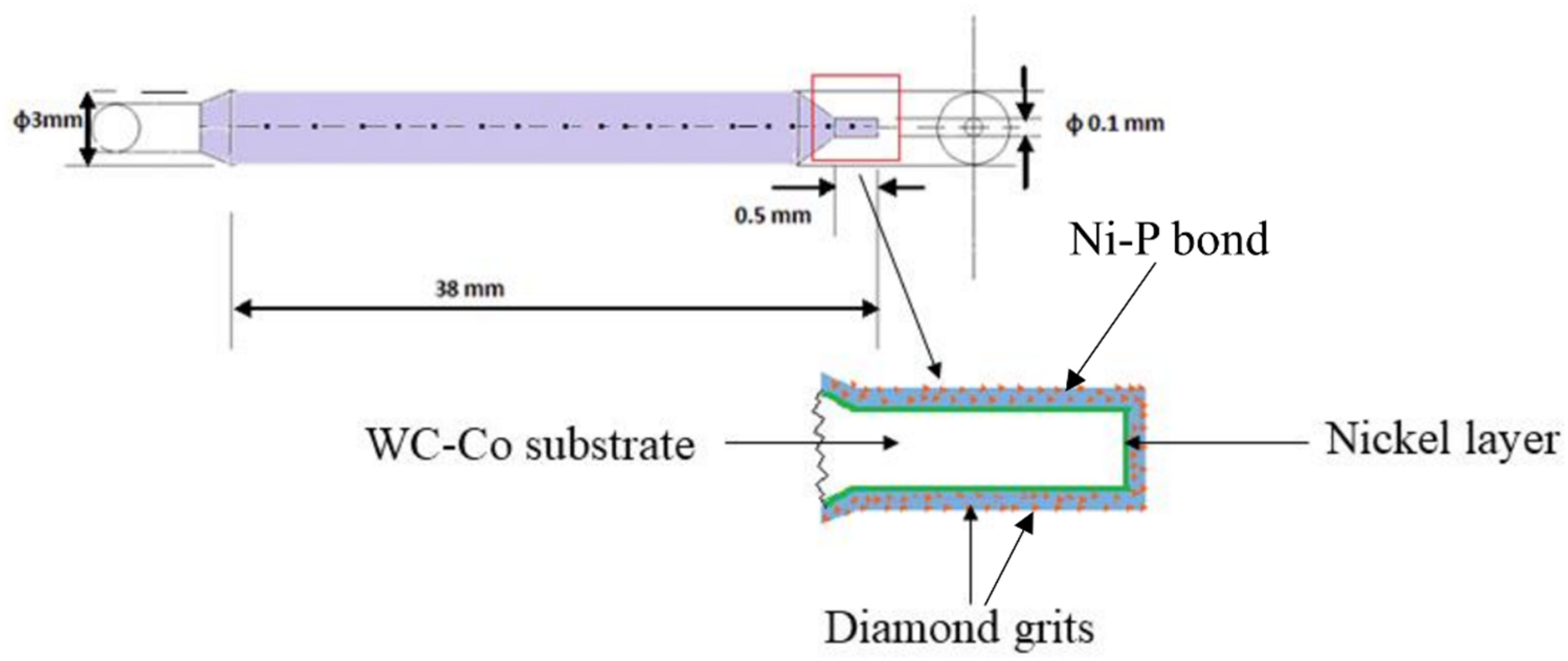
Schematic of the micro-abrasive tool.
A Ni-P-diamond abrasive layer was synthesized surrounding the tip through an electroless process, as illustrated in Figure 1. In the micro-abrasive process, the diamond grits, anchored by the Ni-P bond, shall act as the abrasive cutting points. Prior to the Ni-P-diamond layer, a thin Ni layer was deposited through electroplating route to act as an adhesion layer. Further details about the deposition of the layers are presented in the section ‘
Scanning electron microscopic (SEM) images of the diamond grits and the corresponding energy dispersive spectra (EDS) are shown in Figure 2(a and b), respectively. The size of the diamond grits was in the range of 0–2 μm. As compared to literature,23,29 relatively smaller grits were selected in the present work, which shall enable material removal at a finer scale. Hence, such tools can also be utilized for the removal of micro-burrs formed during various other micro-machining processes.
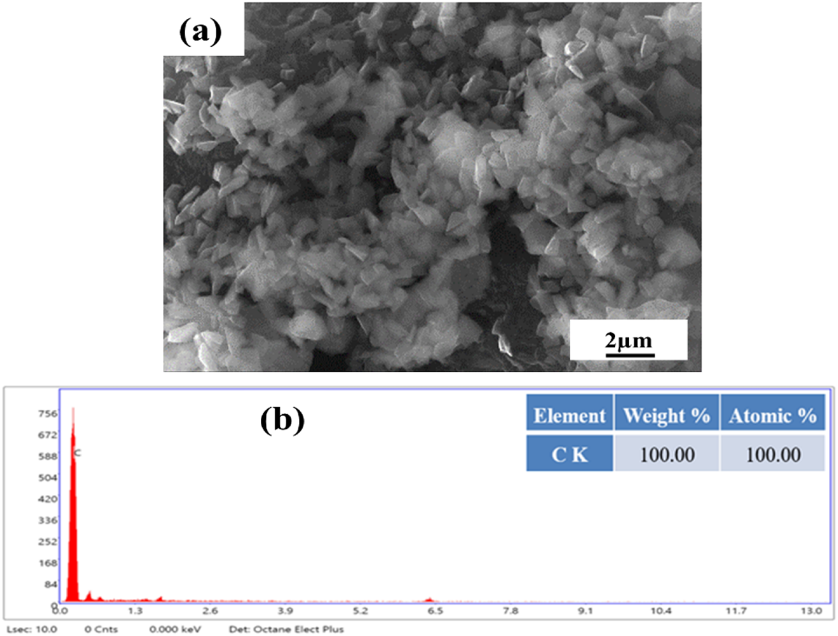
(a) SEM image and (b) EDS analysis of the diamond grits.
Fabrication process of Ni-P-diamond micro-abrasive tool
The process flow for the fabrication of the electroless Ni-P-diamond abrasive layer on the WC-Co micro-substrate is shown in Figure 3. Initially, a chemically resistant shrink tube was put on the shank of the substrate, exposing only the conical portion and the cylindrical micro-tip. The substrate tip was then subjected to cleaning with acetone and degreasing with 200 g/l NaOH solution (temperature 70–80°C and pH 14) to remove greasy and oily substances.30,31 The cleaned substrate was then subjected to mild acid pickling for 10 s in diluted HCl to remove the oxide layers. 32
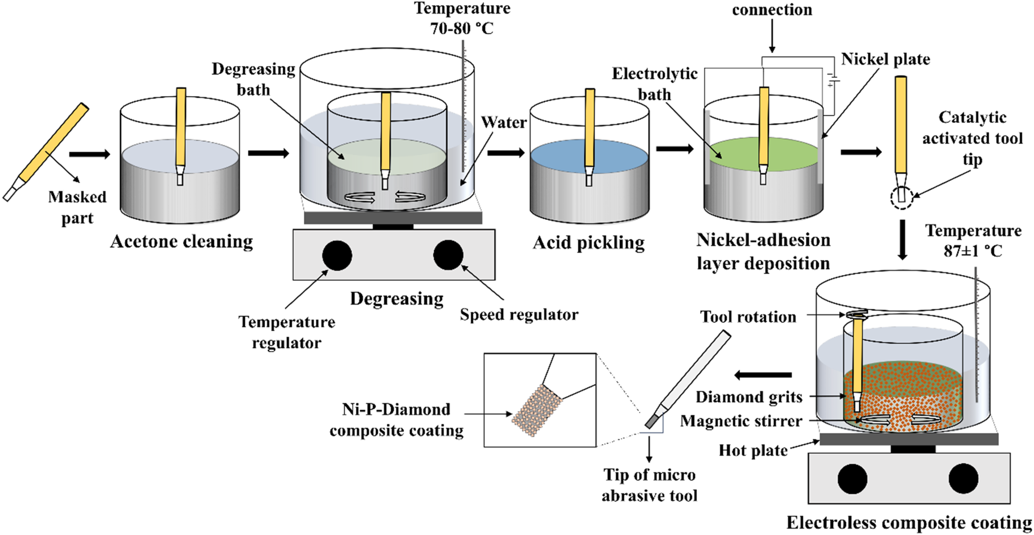
Schematic of workflow for fabrication of Ni-P-diamond abrasive layer on WC-Co micro-substrate.
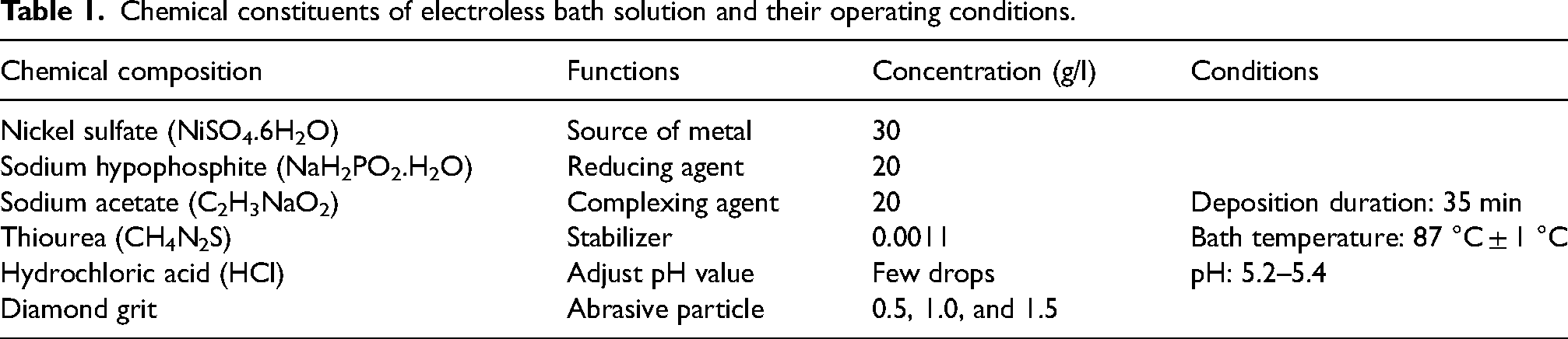
Owing to the composite nature of the substrate involving metallic Co and ceramic WC grains, uniform deposition of electroless Ni-P through an autocatalytic process was challenging. Hence, a thin Ni adhesion layer was initially deposited through an electrolytic process using the substrate as a cathode and high-purity Ni plates as anodes. The electrolyte consisted of NiCl2.6H2O (250 g/l) and HCl (90 ml/l) in distilled water. A current density of 1.5 A/dm2 was applied for 60 s, and the bath was operated at room temperature. The sample was thoroughly rinsed with distilled water before transferring to the electroless bath. In order to deposit the Ni-P-diamond abrasive layer, a composite plating bath of 100 ml was formulated and is presented in Table 1. 24 The diamond grit concentration in the bath was varied at three levels, i.e., 0.5, 1.0, and 1.5 g/l.
Chemical constituents of electroless bath solution and their operating conditions.
The diamond grits were introduced to the bath through two routes, i.e., without and with ultrasonic agitation. In the first route, the required amount of diamond grits (as mentioned in Table 1) were directly added to the Ni-P bath of 100 ml volume, and the solution was subjected to magnetic stirring at 180 rpm throughout the deposition process. For homogeneously distributing the grits all over the surface, the substrate was also rotated at 3 rpm. In the second route, the required quantity of diamond grits was added to a 30 ml sub-bath initially and subjected to ultrasonic agitation for 30 min. The same was then gradually added to the main bath of 70 ml volume through a burette.
After deposition, the micro-tools were rinsed with distilled water and ultrasonically dehumidified with isopropyl alcohol. The samples synthesized with diamond grit concentrations of 0.5, 1.0, and 1.5 g/l and without ultrasonication were identified as WU0.5, WU1.0, and WU1.5, respectively, while the corresponding ones fabricated with ultrasonication were identified as U0.5, U1.0, and U1.5, respectively.
Characterization of Ni-P-diamond abrasive layer
The surface morphologies of the uncoated WC-Co micro-substrate and the Ni-P-diamond coated abrasive layers were visualized using a scanning electron microscope (Zeiss Merlin SEM). Elemental compositions were analyzed with an energy dispersive spectroscopic (EDS) system, integrated with SEM. The thicknesses of Ni-P-diamond abrasive layers were calculated from the difference in diameters of the tool tip before and after deposition. Microhardness of uncoated WC-Co samples (i.e., substrate hardness, HS) and composite hardness (HC) of the coated micro-tools were measured with a Vicker's tester (Leco) under a normal load of 200 gf with a dwell time of 10 s. The value represents the average of five measurements for each sample. Thereafter, values of layer/film hardness (HF) for each coated sample were calculated from the model (equations 1 and 2) proposed by Lesage et al.
33

Here, HC = composite hardness, HS = substrate hardness, HF = layer/film hardness, f = influence factor, t = layer thickness, d = average diagonal length in Vicker's trace, m = Slope of the ln (d)–ln (P) relation
Scratch hardness and adhesion of the abrasive layers were evaluated with a scratch tester (Ducom). For assessing the scratch hardness, the Rockwell C-type diamond stylus was dragged against the sample under a constant load of 10 N at a scratching speed of 0.1 mm/s. The widths of the scratches were measured at five different locations, and the scratch hardness values were calculated using the average width through the method mentioned in literature. 34 Adhesion of the coatings were assessed with a progressive-load scratch test within a load range of 2–32 N, at a scratch speed of 0.1 mm/s and a loading rate of 0.6 N/mm.
Results and discussion
Surface morphology and elemental mapping
Scanning electron microscopic images of the micro-tool tips are presented in Figure 4. Figure 4(a–f) represents the tools fabricated without ultrasonic agitation, while Figure 4(g–l) represents the ones deposited with ultrasonic agitation.
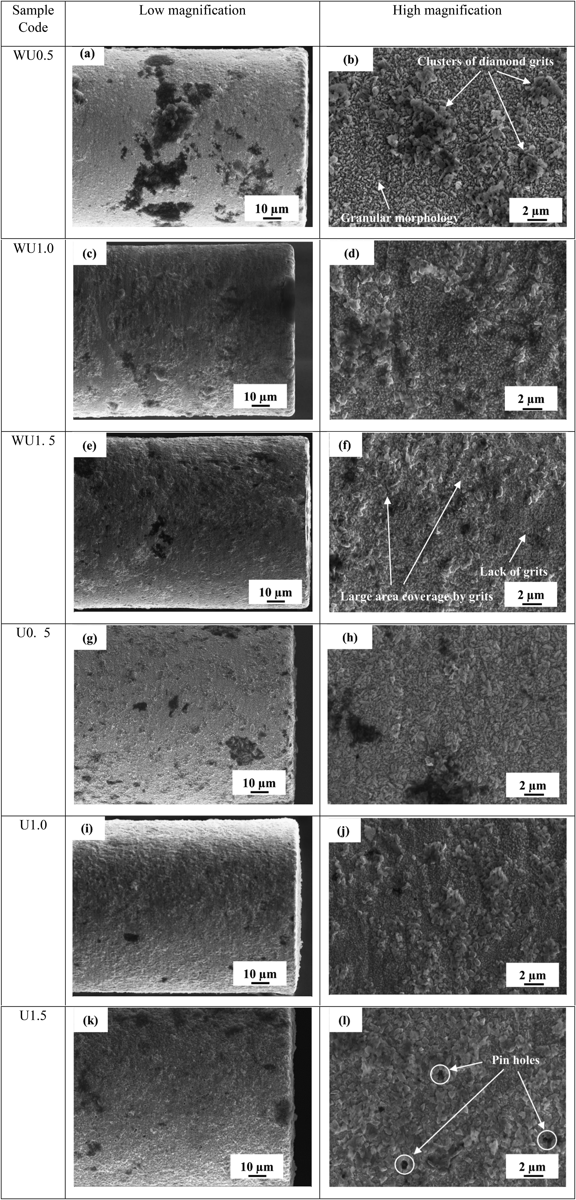
SEM images of the micro-abrasive layers synthesized under different conditions.
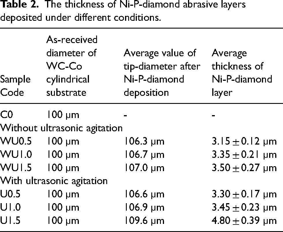
The diameters of the cylindrical tool tips were measured from the SEM images and presented in Table 2. The thickness of the abrasive layers lied in the range of 3.15 to 3.50 μm for the tools synthesized without ultrasonic agitation (i.e., samples WU0.5, WU1.0, and WU1.5), while the same was slightly higher, i.e., 3.3 to 4.8 μm, with ultrasonic agitation (i.e., samples U0.5, U1.0, and U1.5). Reddy et al. 35 reported that there should be an optimum ratio between the thickness of the layer and the size of the abrasive particles for proper integrity. It was observed that the Ni-P layer of 20 μm thickness was appropriate for holding diamond particles of sizes approximately half (6–12 μm) or one-third (3–6 μm) of the layer thickness. In the present work, the layer thickness of approximately 3–5 μm was therefore selected for accommodating diamond particles of 0–2 μm size. It may also be seen that, irrespective of the deposition route, higher content of diamond grit in the bath led to higher abrasive layer thickness. This could be attributed to the incorporation of a larger number of grits into the layer. Further, on incorporation of ultrasonic agitation, increases in the layer thicknesses were noted for all corresponding diamond grit concentrations, particularly 1.5 g/l.
The thickness of Ni-P-diamond abrasive layers deposited under different conditions.
A low-magnification view of the micro-abrasive tool tip synthesized with diamond grit content of 0.5 g/l (Figure 4(a)) showed a distinct morphology as compared to the uncoated substrate. A high-magnification image of the same (Figure 4(b)) showed a ‘granular’ morphology of the Ni-P deposit, in contrast to the typical ‘nodular’ morphology.36,37 A large number of edges, pits, and crevices present in the WC-Co composite substrate acted as adsorption and nucleation centres for the electroplated thin Ni layer and the subsequent electroless Ni-P layer, resulting in such an appearance.24,38 Within the Ni-P layer, diamond clusters of varying sizes were found to remain adhered as islands. However, the distribution of such clusters were quite sporadic in nature, with wide variation in the inter-island spaces. From the perspective of a micro-abrasive tool, such large clusters of diamond grits are not desirable. Within the clusters, some abrasive grits remained hidden, which shall hinder their interaction with the workpiece material. These characteristics shall deteriorate the material-removal ability of the micro-tool. Further, the non-uniformity in surface distribution of the clusters/grits shall also result in irregular tool-workpiece interaction, thereby causing fluctuation in the cutting forces and vibration, ultimately leading to tip breakage. Also, wide variations in the volume of the chip pockets may hamper the performance and life of the tools. The beneficial effect of employing ultrasonic agitation could be clearly seen from the morphology of the micro-tool tip (sample U0.5) shown in Figure 4(g and h). As compared to Figure 4(b), the large clusters of diamond grits were absent. Ultrasonic agitation was effective in breaking the clusters into individual particles or, at least, very small clusters, which ultimately got deposited in a more uniform manner within the Ni-P matrix.
With an increase in diamond grit concentration to 1.0 g/l, the quantity of diamond clusters on the surface of WU1.0 increased (Figure 4(d)). This reflected the positive correlation between grit concentration in the bath and that within the Ni-P matrix. However, the problem of cluster formation and non-uniform spatial deposition persisted. With ultrasonic agitation (Figure 4(j)), large clusters were broken into relatively smaller ones (sample U1.0). Moreover, the inter-cluster space was also found to be more uniform as compared to the one shown in Figure 4(d). With the further rise in diamond grit concentration to 1.5 g/l, the same were found to cover relatively large areas on the tool surface in a continuous manner as compared to islands (Figure 4(f)). However, some regions significantly lacked such grits. The beneficial effect of ultrasonic agitation was quite vivid from the surface morphology shown in Figure 4(l), as it showed a quite uniform distribution of the grits. However, in this case, the diamond grits covered most of the surface area, leaving very little room for chip pockets. This is likely to hamper the performance of the micro-grinding tool. A few pinholes were also noticed, which resulted from the removal of the loosely held diamond grits during post-deposition ultrasonic rinsing.
Elemental maps, showing the distribution of C and Ni over the surfaces of the tools, are presented in Figure 5. Consistent with the SEM images, C clusters of varying sizes were observed for the sample synthesized with 0.5 g/l of diamond without ultrasonic agitation (Figure 5(a)). Application of ultrasonic agitation resulted in a more uniform distribution of C (Figure 5(c)). Though distribution of Ni were mostly uniform for both cases, few voids were observed for the sample WU0.5 (Figure 5(b)). In those regions, diamond grits agglomerated in large quantities, leaving very limited space for Ni deposition. 24 Obviously, such agglomerates shall have very limited inter-grit cohesion as well as poor adhesion with the substrate and are likely to be removed during the initial stages of the micro-grinding operation. Upon incorporation of ultrasonic agitation, such voids were, however, not noticed in the Ni map (Figure 5(d)).
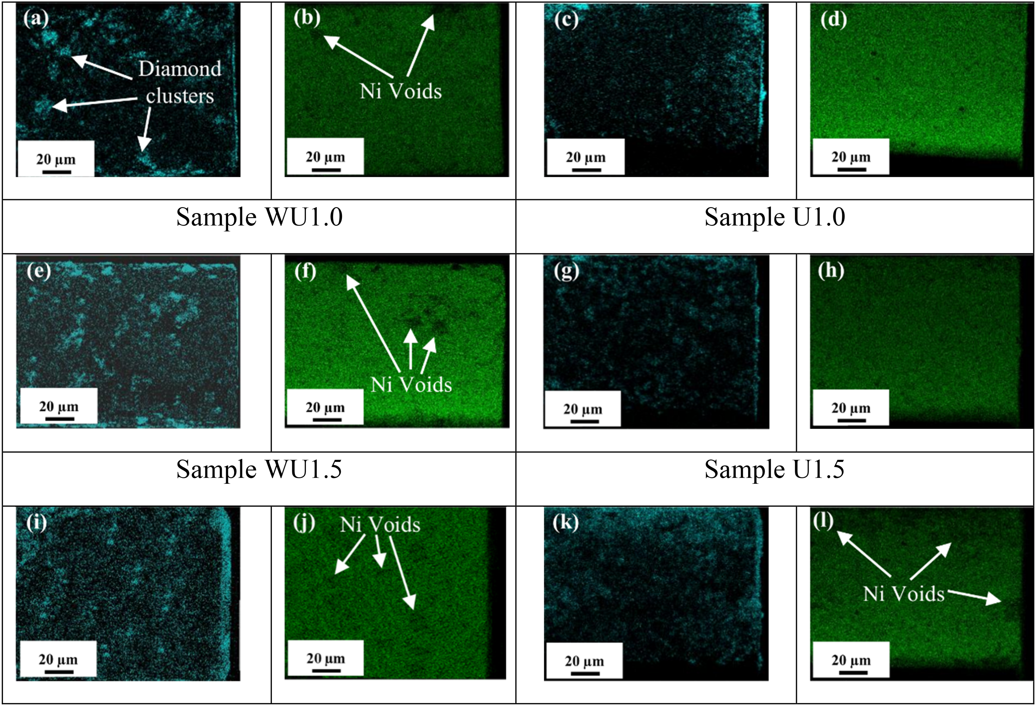
Elemental mapping of C and Ni on the surfaces of the tools.
The effect of increasing the diamond grit concentration to 1.0 g/l was clearly reflected in the increased density of the C clusters in sample WU1.0 (Figure 5(e)). However, the sample synthesized with ultrasonic agitation (U1.0) exhibited a relatively uniform distribution of C (Figure 5(g)). Further, the void regions in the Ni map were almost absent for the sample (Figure 5(h)). With further increase in diamond concentration to 1.5 g/l in the bath, a corresponding increase in the concentration of C was noted for both the samples in Figure 5(i, k). However, excessive incorporation of diamond grits resulted in Ni-void regions even for the sample synthesized with ultrasonication, i.e., U1.5 (Figure 5(l)). The chemical composition of the different abrasive layers fabricated without and with ultrasonic agitation is presented in Table 3.
Elemental composition of Ni-P-diamond abrasive layers.
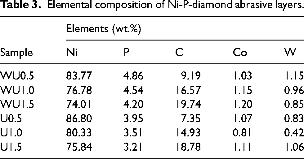
Irrespective of the fabrication route, all samples exhibited P content from 3 to 5 wt.%, and accordingly, they could be categorized as low to marginally medium phosphorus electroless Ni-P deposits. An increase in the concentration of diamond grits in the bath solution resulted in a corresponding increase in C wt.%. This was true for the samples fabricated both without (WU0.5, WU1.0, WU1.5) and with (U0.5, U1.0, U1.5) ultrasonic agitation. However, as is evident from Table 3, the percentage rise in C content was less for the samples (WU1.5 and U1.5) fabricated with the highest grit concentration of 1.5 g/l as compared to the previous corresponding samples. This indicated that the incorporation of diamond grits was increasingly difficult towards higher grit concentration due to the lack of available space in the Ni-P bond. A further magnified region of Figure 4(l) (sample U1.5), presented in Figure 6, showed that the grits mounted on each other. Such grits would have minimum inter-grit bonding and would be easily removed during the micro-grinding operation. At higher grit concentration in the bath the densely floating particles causes scattering, absorption of ultrasonic energy, and reduction in the intensity of the cavitation process.39,40 Also, at constant bath volume, higher particle concentrations result in an increased particle collision frequency. 41 If enough local activation occurs, more frequent collisions can cause particles to stick together and form larger clumps. Hence, at higher grit concentration in the bath, ultrasonic agitation became ineffective in breaking the diamond clusters.
(a) High magnification SEM image of sample U1.5, (b) Further magnified view of the marked region showing agglomeration and mounting of diamond grits over each other.
Vicker's microhardness test
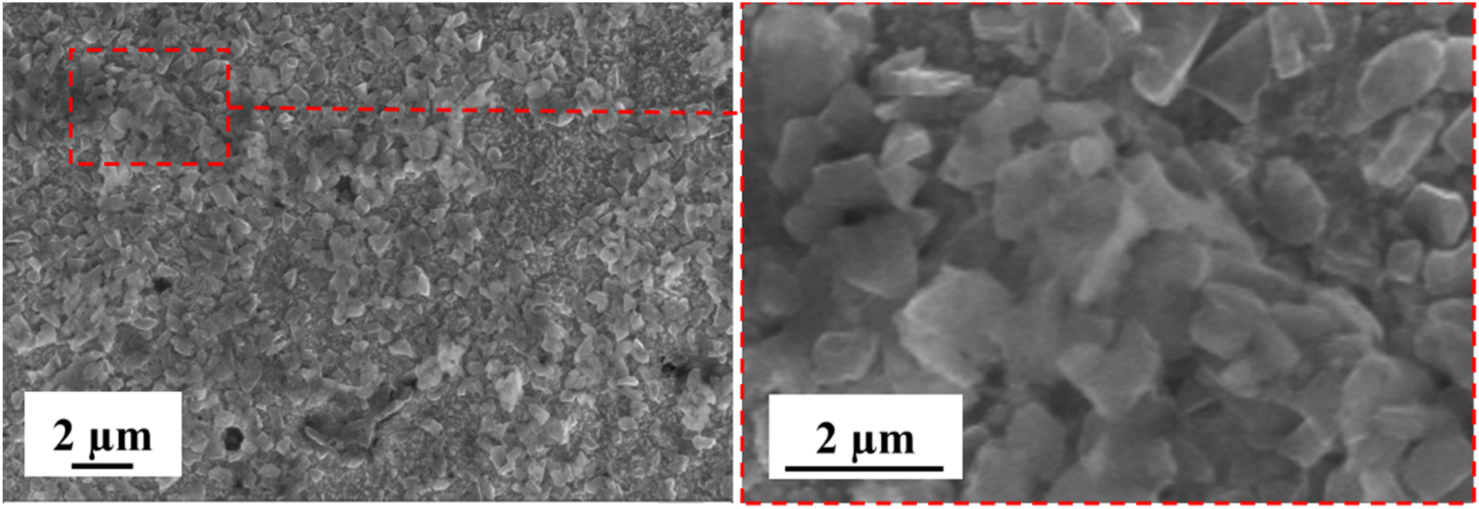
Microhardness of uncoated WC-Co substrate and Ni-P-diamond abrasive coated tools are presented in Table 4. The corresponding Vicker's impressions are presented in Figure 7. An average microhardness value of 1910 HV0.2 was registered for the uncoated WC-Co substrate.1,24 The composite microhardness of the sample WU0.5 was measured to be 1208 HV0.2. The corresponding film hardness was 779.4 HV0.2. This film hardness value was slightly higher than the reported hardness of approximately 700 HV for Ni-P coating on WC-Co substrate 23 and could be attributed to the presence of diamond grits within the Ni-P bond. Wang et al. 42 however, reported a hardness of approximately 600 HV for the Ni-P-diamond composite layer of 30 μm thickness with a particle size of 2 μm, deposited on mild steel substrate. Further, in the present work the 0–2 μm sized diamond grits dispersed within the thinner layer of 3–5 μm thickness possibly transmitted the applied load to the substrate by forming ‘diamond bridges,’ resulting in higher hardness.
Vicker's impressions on uncoated and coated samples under normal load of 200 gf.
Microhardness and scratch hardness values of uncoated WC-Co and Ni-P-diamond coated samples.
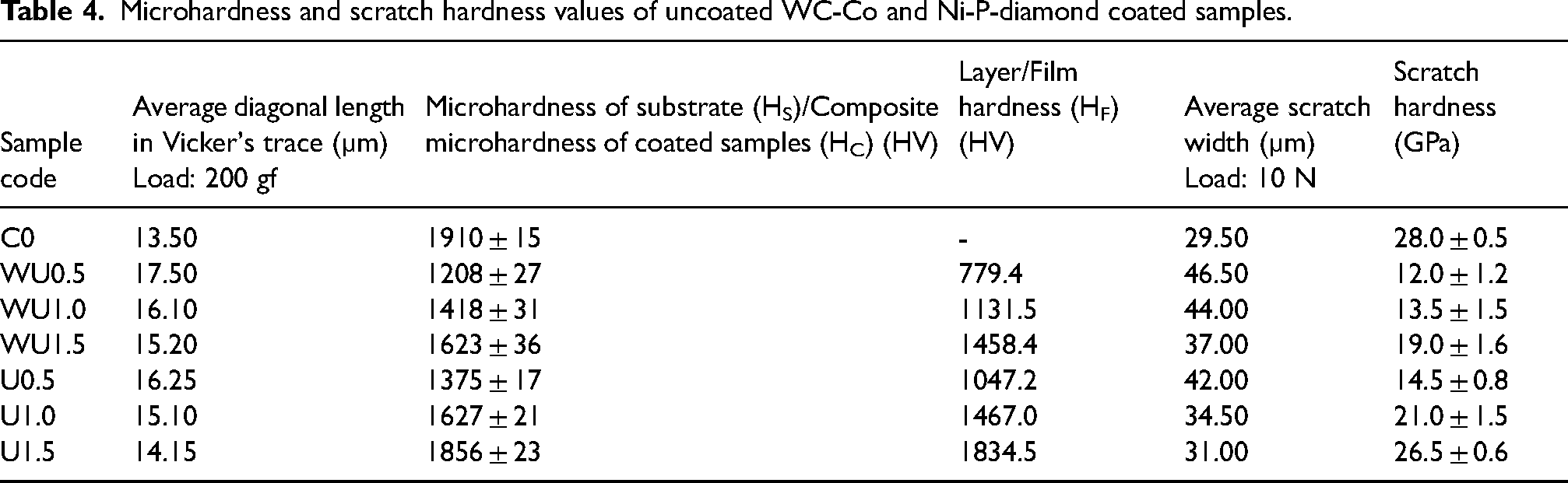
With an increase in diamond grit concentration to 1.0 and 1.5 g/l in the bath, composite hardness increased to 1418 HV0.2 and 1623 HV0.2, respectively (sample WU1.0 and WU1.5 respectively). The corresponding film hardness values were calculated to be 1131.5 HV0.2 and 1458.4 HV0.2 respectively. At higher grit concentrations, increasingly higher numbers of diamond grits occupied the surface area of the tools, as shown in the surface morphologies illustrated in Figure 4(a–f) and the EDS maps presented in Figure 5(a, e, i). Therefore, the direct interaction of the indenter with the relatively softer Ni-P matrix was progressively reduced at higher grit concentrations, which led to increased hardness. Further, it may be observed from Figure 2(a) that the diamond grits were blocky in shape. When a normal load was applied, the grits likely interlocked with one another, which prevented their displacement or rotation. The increase in layer thickness with diamond grit concentration (Table 2) might also have a minor role in enhancing the microhardness.
On employing ultrasonic agitation, corresponding increases in hardness were however, observed at all concentrations of diamond grits, in the range of 1375 HV0.2 to 1856 HV0.2. The corresponding film hardness values were in the range of 1047.2 HV0.2 to 1834.5 HV0.2. The same may be attributed to the more uniform distribution of the diamond grits, which effectively minimized the contact area of the indenter with the Ni-P matrix. Further, the standard deviation of the composite hardness values was relatively less for the samples deposited with ultrasonication (U0.5, U1.0 and U1.5), suggesting the uniform placement of the grits. Vicker's traces of the Ni-P-diamond coated samples did not reveal any obvious cracks. This is important as the brittle Ni-P-diamond layer may fail through crack propagation during the micro-grinding operation.
Scratch hardness and adhesion tests
The average widths of the scratches and the corresponding scratch hardness of WC-Co and Ni-P-diamond coated samples are presented in Table 4. Corresponding images of the scratch tracks are shown in Figure 8.

(a-g) Images of scratches obtained at a constant load of 10 N (h) variation of friction force over scratch length for sample U1.0.
The uncoated WC-Co substrate exhibited an average scratch width of 29.5 μm (Figure 8(a)) and a corresponding scratch hardness of 28 GPa. 43 In comparison, the Ni-P-diamond abrasive layer, synthesized with 0.5 g/l of diamond grits and without ultrasonication (sample WU0.5), exhibited a notably wider scratch (Figure 8(b)) and, consequently, significantly lower scratch hardness of 12 GPa. This was primarily because of the softer Ni-P deposit with a minimum content of diamond grits. However, at higher grit concentrations of 1.0 g/l (WU1.0) and 1.5 g/l (WU1.5), initial vertical penetration of the conical scratch stylus into the layer was restricted, leading to narrower scratches (Figure 8(c) and (d)). Also, at higher grit concentration, the stylus more frequently encountered the diamond grits rather than the soft Ni-P bond, which restricted the ploughing and lateral deformation of the abrasive layers, leading to narrower scratch widths. These effects led to higher scratch hardness. However, no evident signs of edge spallation were noticed, even at higher grit concentrations of 1.0 g/l and 1.5 g/l (Figure 8(c) and (d)).
The beneficial effect of ultrasonication could be clearly observed by the relatively narrower scratch widths at corresponding diamond grit concentrations as compared to those without ultrasonication (Figure 8(e)-(g)). As evident from the SEM images, ultrasonication led to more uniform distribution of the diamond grits over the entire surface. This resulted in higher film hardness of the abrasive layers (Table 4) and consequently narrower scratch widths and higher scratch hardness, as discussed previously. A typical friction force profile, obtained while scratching the Ni-P-diamond abrasive layer (sample U1.0), is shown in Figure 8(h). Over the entire scratch length, the friction force essentially remained constant at around 1.0 N. No major signs of fluctuations in the friction force were noted, indicating that the coating did not suffer from any delamination during the test. This is important, as localized delamination in the abrasive layer may change the nature of contact at the tool-workpiece interface, leading to fluctuations in the forces and ultimately result in tool failure.
Rise in friction force during progressive load scratch tests of some selected Ni-P-diamond coated samples are presented in Figure 9. For the sample WU0.5, deposited with 0.5 g/l diamond grit concentration and without ultrasonication, a fluctuating nature of the friction force could be observed (Figure 9(a)). The corresponding scratch track (Figure 10(a)) exhibited exposed substrate at several regions. Piling of coating along the edges of the scratch track was also observed. 44 This resulted from ploughing of the relatively softer Ni-P-diamond layer owing to the minimum content of diamond grits (0.5 g/l). Increasing the diamond grit concentration to 1.5 g/l (sample WU1.5) led to a much steady friction force profile till the highest normal load of 32 N (Figure 9(b)). The corresponding image of the scratch track (Figure 10(b)) also did not reveal any sign of failure.
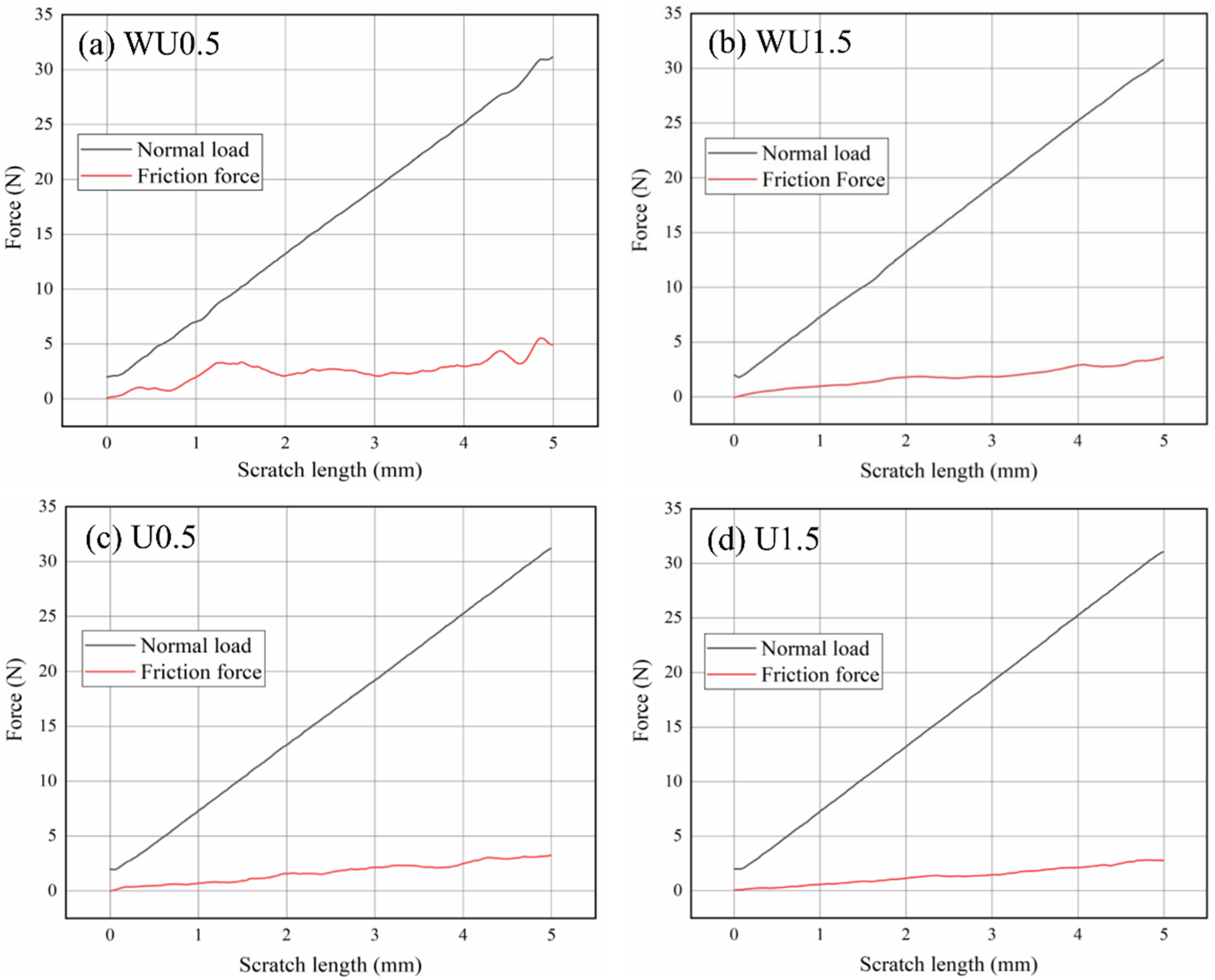
Variation of friction force during progressive load scratch tests of selected Ni-P-diamond coated samples.
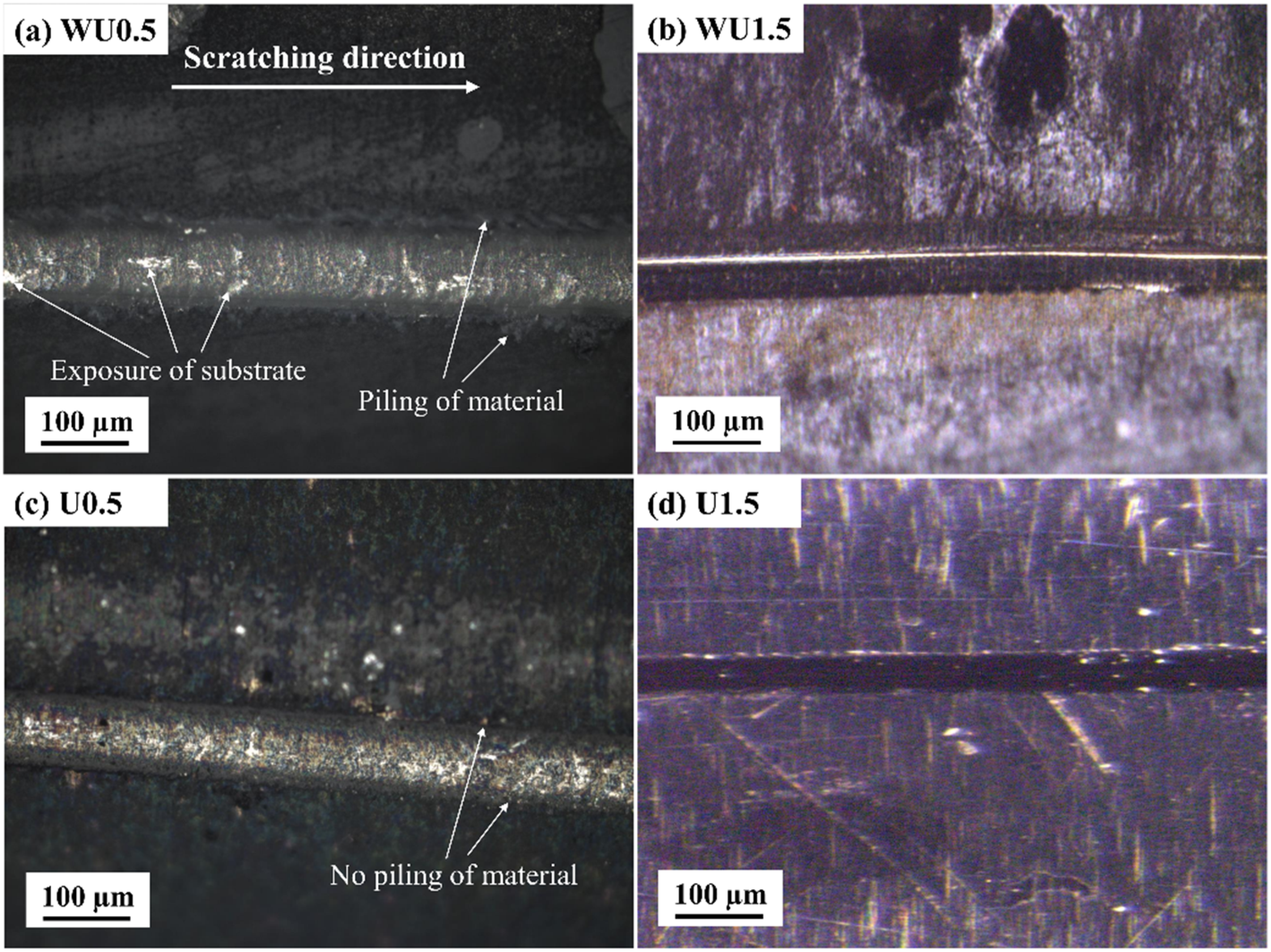
Images of scratch tracks on samples: (a) WU0.5, (b) WU1.5, (c) U0.5 and (d) U1.5 under progressive loading.
Upon incorporation of ultrasonic agitation (sample U0.5), the friction force profile did not exhibit any significant fluctuation (Figure 9(c)) till the peak normal load. It was unlike its counterpart without ultrasonic agitation, i.e., sample WU0.5 (Figure 9(a)). The corresponding scratch track was also relatively smoother without any significant substrate exposure (Figure 10(c)). The uniform placement of diamond grits within the Ni-P matrix (Figure 4(h)) effectively resisted the penetration of the scratch stylus, resulting in less substrate exposure. The scratch track also did not suffer from any piling of material along the two edges. Owing to the higher film hardness of U0.5 as compared to WU0.5, the ploughing of the former was significantly reduced. For the sample U1.5, deposited with 1.5 g/l diamond grits with ultrasonication, the friction force curve was still smoother (Figure 9(d)) as compared to its counterpart, i.e., WU1.5 (Figure 9(b)). Further, it is important to note from the corresponding scratch image of U1.5 (Figure 10(d)) that the Ni-P-diamond layer also did not suffer from any brittle flaking along the edges in spite of its highest film hardness of 1834.5 HV0.2 among all the coated samples (Table 4).
Conclusions
Electroless Ni-P-diamond composite layers were deposited on WC-Co micro-substrates to develop micro-abrasive tools. Effects of variation of grit concentration as well as ultrasonication were investigated on morphology, elemental distribution, chemical composition, microhardness, scratch hardness, and scratch adhesion of the layers. The results led to the following conclusions.
An increase in the concentration of diamond grits in the electroless bath solution led to the inclusion of more grits within the deposited Ni-P matrix. However, the grits adhered to form clusters of varied sizes with non-uniform inter-cluster gaps. Application of ultrasonic agitation led to the appearance of smaller clusters with uniform spaces in between them. However, towards higher grit concentration of 1.5 g/l, ultrasonication was ineffective towards segregating the clusters. The thickness of the abrasive layers lay in the range of 3.15 μm to 4.80 μm and had a positive correlation with the diamond grit concentration, irrespective of the method of deposition. However, the layers deposited with ultrasonication were thicker as compared to their counterparts deposited without ultrasonication. Elemental maps of Ni for the samples deposited without ultrasonication revealed certain regions (identified as Ni-voids) where the diamond grits agglomerated in large quantities, leaving very little room for Ni deposition. Ultrasonic agitation eliminated such Ni-void regions for the samples with 0.5 and 1.0 g/l diamond concentration. With an increase in the concentration of diamond grits in the bath solution, a corresponding rise in C wt.% in the abrasive layers were observed. However, owing to a lack of available space in the Ni-P bond, incorporation of diamond grits was increasingly difficult at a higher grit concentration of 1.5 g/l. Composite microhardness of coated samples scaled with diamond grit incorporation, in the range of 1208 to 1623 HV0.2 for those deposited without ultrasonication. The corresponding film hardness values were calculated to be from 779.4 to 1458 HV0.2. With the application of ultrasonication, the composite microhardness values were enhanced to the range of 1375 to 1856 HV0.2. The corresponding film hardness values also increased and lied in the range of 1047.2 to 1834.5 HV0.2. The standard deviation of the hardness values also reduced on application of ultrasonic agitation, due to more uniform distribution of the diamond grits within the Ni-P matrix. In the constant-load scratch tests, higher scratch hardness was measured at higher diamond grit content. This trend was consistent for the samples deposited both without and with ultrasonication. The values lied in the range of 12 to 19 GPa for the samples deposited without ultrasonication, while the same was in the range of 14.5 to 26.5 GPa for the samples deposited with ultrasonication. Incorporation of ultrasonic agitation led to more uniform diamond grit distribution and higher film hardness, which in turn led to narrower scratches and accordingly, higher scratch hardness. In the progressive-load scratch tests, localized removal of the Ni-P-diamond layer was observed within the scratch track at higher loads. Ploughing of the relatively soft Ni-P-diamond layer (containing 0.5 g/l of grits, without ultrasonication) was also noticed. On employing ultrasonication, such ploughing of material was eliminated. The same benefit was also realized at a higher grit concentration of 1.5 g/l, irrespective of the deposition route.
Footnotes
Acknowledgements
The authors gratefully acknowledge the support received from the Machine Tools and Machining (MTM) Laboratory, Mechanical Engineering Department, IIT Kharagpur, regarding the SEM observations. The authors are also grateful to Dr Soumya Gangopadhyay, IIT Bhilai for useful discussions.
Data availability statement
The authors state that the data regarding the study are available in the article.
Declaration of conflicting interests
The authors declared no potential conflicts of interest with respect to the research, authorship, and/or publication of this article.
Funding
The authors disclosed receipt of the following financial support for the research, authorship, and/or publication of this article: The authors are grateful to Anusandhan National Research Foundation (erstwhile SERB), Department of Science and Technology, Government of India, for providing necessary funding under the Core Research Grant Scheme (Project No: CRG/2022/008771) to conduct this study.