
Abstract
Al6061 alloy is an environmentally friendly engineering material extensively used in the aviation, construction, and shipbuilding industries; however, its tribo-mechanical performance is relatively limited and can be enhanced by grain refinement induced by the friction stir process (FSP). The current study investigates the influence of carbon-rich tribofilm formation on the tribo-mechanical performance of carbon-nanotube (CNT)-reinforced Al6061 composites processed via multi-pass FSP. Raman spectroscopy confirmed the retention of structurally modified carbon in the nugget zone due to FSP-induced plastic strain, evidenced by a progressive increase in ID/IG ratio (raw CNT ∼ 0.74; T/CNT-2 ∼ 0.87), which was further supported by scanning electron microscopy. Crucially, no Al4C3 interfacial phase was detected by XRD, confirming that CNTs retained structural integrity as lubricating reinforcements. The CNT-reinforced composite (T/CNT-2 ∼ 123.57 HV) exhibited a substantial enhancement in hardness as compared to the unprocessed sample (O ∼ 62.87 HV), primarily due to crystallite size refinement (from O ∼ 47 nm to T/CNT-2 ∼ 24 nm). Tribological investigations revealed a significant reduction in the coefficient of friction (COF) from 0.80 for the untreated sample to 0.51 for the CNT-reinforced metal matrix composite (MMC), accompanied by a substantial reduction in wear volume from 0.2427 × 10⁻³ mm3 to 0.0531 × 10⁻³ mm3. The improved tribological behaviour is associated with the in situ formation of a carbon-rich lubricating tribofilm developed from CNT reinforcement. Scanning electron microscopy confirmed adhesive wear as the dominant wear mechanism, with a cracked tribolayer developed due to cyclic stress during fretting wear. The CNTs-reinforced composite demonstrated the lowest frictional force with minimum energy dissipation of 5.1 × 10⁻⁴ J/cycle compared to 8 × 10⁻⁴ J/cycle for the untreated sample (∼ 36% reduction). The improved performance demonstratre the development of self-lubricating, carbon-rich tribofilm, which enhances the tribo-mechanical performance of Al6061 composites for wear-resistant applications.
Introduction
Al6061 alloy is widely used in shipyards, automobile, and aerospace sectors owing to its good strength-to-weight ratio, but its extended utilisation is limited due to its poor tribological performance. 1 Aluminium metal matrix composites (MMCs) have attracted remarkable attention compared to conventional alloys due to their superior tribo-mechanical performance. Among commonly used reinforcements, SiC and Al₂O3 are the most widely used to enhance the tribo-mechanical performance of Al6061 alloy.2–3 Among various reinforcements, carbonaceous reinforcements, including CNTs, graphene, and graphite, are preferred for Al alloys due to their excellent thermal conductivity and inherent self-lubricating properties. 4 F. Akhlaghi et al. 5 showed that graphite reinforcement markedly improves the tribological resistance of Al2024 composites, achieving a reduction of nearly 40–60% in wear due to the initiation of a stable tribolayer. Powder metallurgy, along with casting, is the most widely utilised process for the fabrication of aluminium-based MMCs.4,6 Hakan Ada et. al. 7 reported that AA6061 composites reinforced with B4C, SiC, and TiC via powder metallurgy exhibited improved tribo-mechanical performance as compared to the monolithic alloy. The hybrid B4C–SiC composite achieved the highest hardness increase (∼ 101%) and enhanced wear resistance (∼ 46–47%), primarily due to improved interfacial load-transfer mechanisms. Baradeswaran et al. 8 investigated Al6061 composites reinforced with 5–15 wt.% graphite fabricated via the casting technique and reported that the composite containing 5 wt.% graphite exhibited the lowest specific wear rate (0.006–0.008 mm2/m) as correlated to the mololithic Al6061 alloy (0.008–0.012 mm2/m). Conventional MMC fabrication methods, such as powder metallurgy and casting, often result in non-uniform reinforcement distribution, limiting their performance. To address this, the friction stir process was applied to accomplish an even dispersion of reinforcing particles, which is essential for enhancing the tribo-mechanical performance of MMCs.1,9 FSP was initially developed for Al-based MMCs to achieve microstructural modifications and later extended to Mg and other metal alloys. 10 The process significantly improved the tribo-mechanical properties of the material by refining its microstructure. Being a thermo-mechanical process, it also ensures uniform dispersion of reinforcing particles within the MMC.11,12 During the friction stir process, the rotating tool produces frictional heat and intense plastic deformation in the nugget zone, resulting in substantial microstructural refinement. 13 Due to the pronounced heat generation between the workpiece and tool, the microstructure shows three distinct stirred zones, namely the weld-affected zone (WAZ) (Figure 1). The first heat-affected zone is the dynamic recrystallised zone (DXZ), also referred to as the stir or nugget zone. A stir or nugget zone is a plastically deformed zone that contains finer grain structures compared to the base material. A zone containing a dual transition zone, usually referred to as the Thermo-Mechanically Affected Zone (TMAZ), is shown in Figure 1. In contrast, the heat-affected zone (HAZ) experiences negligible plastic deformation, and its microstructural evolution is predominantly governed by the thermal energy of deformation. 14 Furthermore, in addition to the above characteristics of FSP, several authors have shown that varying FSP passes affect the tribo-mechanical performance of MMCs and reported enhanced properties resulting from the even distribution of reinforcements within the MMCs.15,16 Saeed Ahmadifard et al. 17 developed Al7075 MMCs reinforced with Ti3AlC₂ particles through the friction stir process. The study demonstrated that multi-pass FSP markedly improved the mechanical performance, with yield and tensile strengths increasing by 2–5% after one pass and by 19–20% after four passes. Additionally, a notable enhancement in microhardness was observed, rising from 17% for a single pass to 33% after four passes. Dongchen Zhao et al. 18 demonstrated that friction stir processing of nano-SiC/nano-graphite reinforced Al5052 composites resulted in pronounced microstructural refinement, reducing the grain size from 145 micrometres to 2.5–3 micrometres (∼ 97–98% reduction). The hybrid composite attained an ultimate tensile strength of 227 MPa (∼ 29% improvement) and a yield strength of 130 MPa (∼ 97% increase) relative to the monolithic alloy. In addition, the specific wear rate decreased by 33.3%. A consistent trend of tribo-mechanical enhancement in FSP-processed aluminum-based composites has been reported in the works of L. Feroz Ali et al. and R. Soundararajan et al. across various aluminum alloy systems reinforced with tungsten-based nanoparticles. The severe plastic deformation during FSP promotes grain refinement and uniform particle dispersion, leading to improved performance of the composites.19–25 Ilyas Hussain et al. 26 fabricated AA6061/TiAl composites via FSP, achieving significant grain refinement (∼ 88% reduction) and enhanced hardness. Notwithstanding the considerable research effort devoted to studying CNT- and graphene-based Al MMCs formed by FSP, there is a crucial knowledge deficit regarding the in situ formation of carbon-rich tribofilms and the extent of their influence on frictional behaviour under fretting wear conditions. While current investigations of FSP-CNT composites show improvements in COF and wear volume, none have provided spectroscopic or microscopic evidence of tribofilm formation.4,6,27 Additionally, the effects of CNT structure transformation through FSP on tribofilm formation have not been studied. Although notable advancements have been achieved in the fabrication of CNT-reinforced composites via FSP, several crucial aspects remain to be investigated. First, the mechanism behind the degradation of CNT due to strain induced by FSP, and the effect of this degradation on the generation of a tribo-carbon film lubrication layer, have not yet been fully clarified. Second, although multi-pass FSP is effective in improving CNT dispersion, its specific effect on enhancing tribofilm stability beyond dispersion is not well known. Third, no clear relationship has been reported between crystallite size reduction and wear resistance.

Schematic representation of microstructural alteration via FSP process. AS denotes the advancing side (tool's rotational motion is aligned with the traverse direction) while RS denotes the retreating side (tool rotates opposite to the traverse direction).
The current research will comprehensively address these research problems. Furthermore, the energy dissipation behaviour during fretting and the mechanism underlying the development of self-lubrication through fretting wear will be elucidated.
Materials and methodology
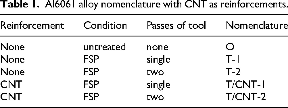
Al6061 alloy (Al - 97.80 wt.%, Si - 0.94 wt.%, and Mg– 0.76 wt.%) is utilised as the base material for the friction stir process. Carbon particles such as CNTs (0.67 wt.%) are employed as a reinforcing material in the metal matrix (Figure 2(b)). FSP was performed on a rectangular sheet having dimensions of 10 mm × 15 mm × 2 mm (Figure 3(c)). A Concept Mill 105 milling machine with a description of 5 horsepower was initially used for conducting experiments. FSP was performed using a cylindrical-shaped mild steel tool (shoulder dia 6 mm, probe dia of 3 mm, and probe length of 1.5 mm), as illustrated in Figure 3(a), b showing the rotating tool and the process methodology. Further, FSP was carried out under optimised conditions (1300 rpm, 1.2 mm plunge depth, 0.3 mm/min traverse speed) to ensure adequate material plasticization and consolidation. Prior to processing, a 0.4 mm surface groove was created in Al6061 for CNT reinforcement (Figure 3(c)). The CNT agglomeration-prevention strategy was specifically developed for the groove-filling process. To prevent agglomeration during groove filling, CNT powder was sonicated in ethanol for 30 min, then the solvent was evaporated prior to groove filling, yielding a homogeneous suspension. The multi-pass (1 and 2) FSP process leads to repeated severe plastic deformation, resulting in further mechanical dispersion of CNT clusters (Figure 7). Selection of the number of friction stir passes (1 and 2) was made according to the results of preliminary parametric investigation, which showed that one pass provides primary CNT incorporation, but two passes provide optimal dispersion homogeneity and grain refinement while preventing overheating effects such as grain enlargement because of excessive heat input into the processed sample. Further, the temperature value during the FSP process was estimated with the help of the equation proposed by Arbegast & Hartley: T/Tm ≈ K(ω2/v)α, where ω and v are the rotational (1300 rpm) and traverse speeds (0.3 mm/min), respectively; K and α are material constants. For Al6061 alloy, the estimated temperature range is 450–520°C (0.82–0.93 Tm). This temperature falls within the dynamic recrystallisation temperature range of aluminium alloys (∼ 0.7–0.9 Tm).13,28,29 Furthermore, Table 1 depicts the adopted nomenclature in the current investigation.
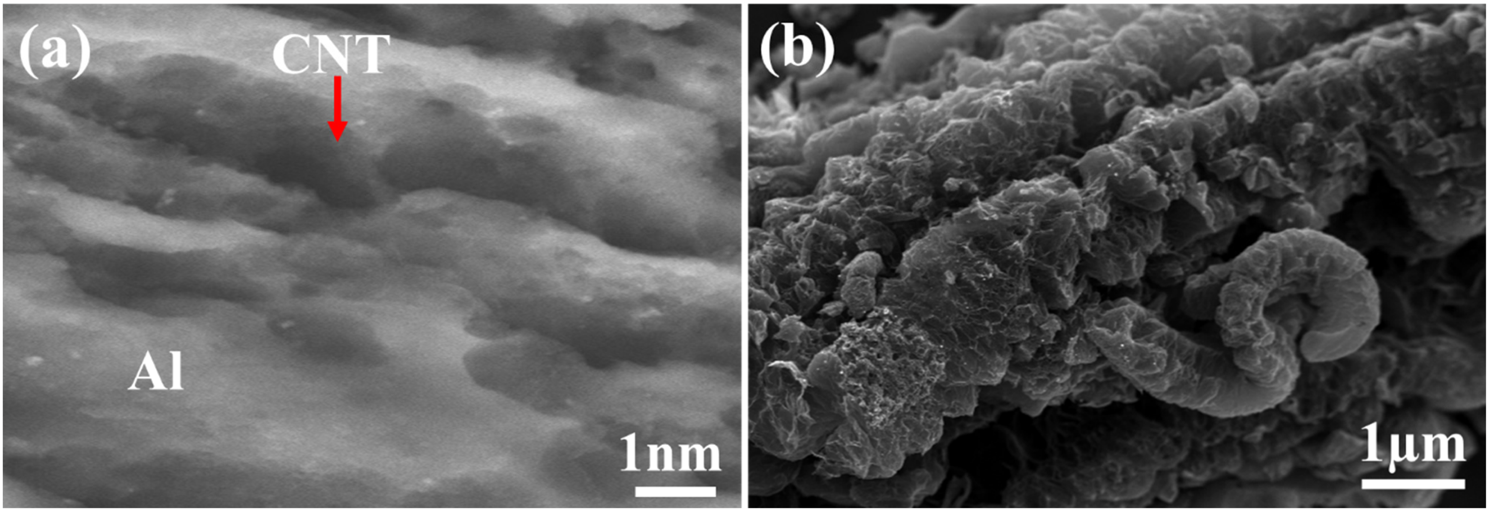
Scanning electron images (SEM) (a) CNT-reinforced Al6061 composite (b) raw CNT powder.
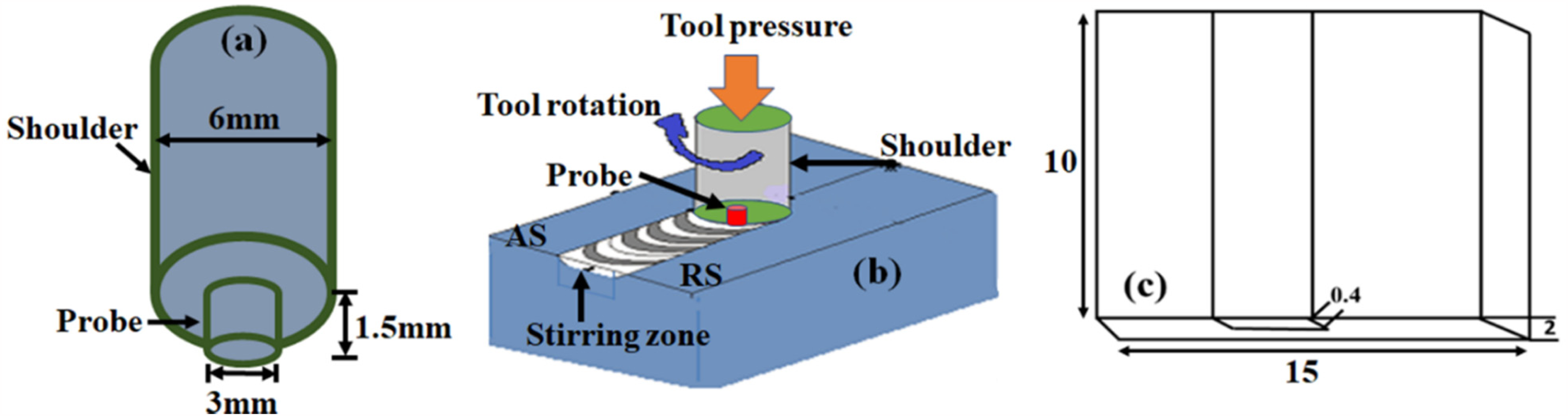
Representation of (a) tool geometry (b) FSP mechanism (c) Al6061 grooved sheet utilized CNT as reinforcement (all dimensions are in mm). AS denotes the advancing side (tool's rotational motion is aligned with the traverse direction) while RS denotes the retreating side (tool rotates opposite to the traverse direction).
Al6061 alloy nomenclature with CNT as reinforcements.
Results and discussion
Constituent phases with micro-macro structural features
For microstructural examination, the workpiece was mirror-polished, followed by using Keller's reagent for etching purpose. Phase analysis of both FSP-processed and untreated samples was conducted using X-ray diffraction (XRD) with Cu–Kα radiation (λ = 1.54 Å) at 15 mA and 30 kV. XRD analysis revealed the peak intensities of Al and Al–Fe–Si precipitates (Figure 4). Importantly, there was no formation of peaks corresponding to the formation of Al4C3 (peaks expected around 2θ = 31.2°, 36.7°, and 52.3°), indicating that no adverse interface reaction between aluminium and carbon took place during the friction stir process. The importance of the lack of peaks associated with Al4C3 stems from its hygroscopicity, which reduces the mechanical performance of aluminium/carbon nanotube composite materials. 27
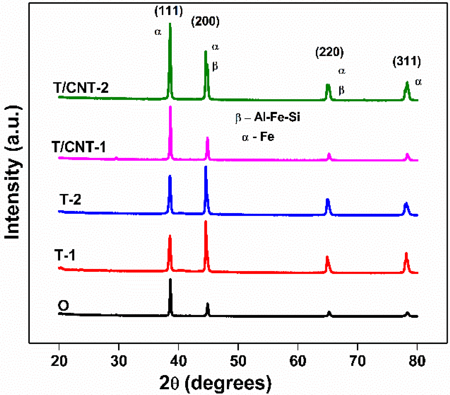
XRD profile of untreated and FSP samples.
Notable shifts in peak position and intensity after the process indicate the FSP-induced plastic strain during the processing.
28
The observed Crystallite size (D) was determined by using Scherrer's equation (Table 2).
Experimental correlation between tribo-mechanical properties of MMC
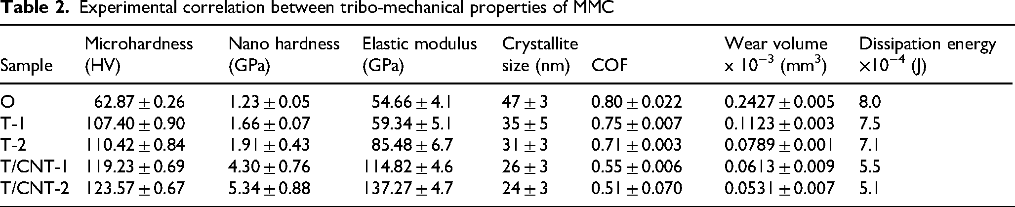
In the mentioned equation, K is referred as Scherrer's constant (0.9), θ is the Bragg's diffraction angle, λ denotes the wavelength of the X-ray radiation, and β represents the full width at half maximum of the diffraction peak, reflecting peak broadening. Through XRD analysis, the CNTs-reinforced composite processed with two tool passes (T/CNT-2) exhibited the smallest crystallite size (∼ 24 nm), in contrast to the untreated alloy (∼ 47 nm), confirming pronounced grain refinement induced by multi-pass FSP. The strain induced during processing facilitates grain elongation along the deformation direction and reduces the average crystallite size. 27 Macrographic analysis indicates a preferential flow of plasticized material towards the advancing side, reflecting the inherent asymmetry of the process (Figure 5). Furthermore, high-resolution optical micrographs were employed to demonstrate the microstructural features of the samples during the process (Figure 6). The stir zone (SZ) exhibits fine, grains of equiaxed morphology formed via dynamic recrystallization, indicating the evolution of a homogeneous microstructure (Figure 6(b)). In contrast, the HAZ exhibits coarse grains due to thermal exposure without recrystallization. Meanwhile, the TMAZ displays distorted, elongated grains resulting from combined thermal and mechanical effects, indicating its transitional nature between the SZ and HAZ (Figure 6(c), d). Controlled optimization of FSP parameters enables controlled flow of plasticized material through which desired modification in the metal matrix can be achieved. 30 Qualitative homogeneity of CNT dispersion was assessed from SEM micrographs (Figure 2(a)), while quantitative homogeneity of the CNT distribution was evaluated by analysis of SEM images using ImageJ software, resulting in the CVs (Coefficient of variations) of ∼ 12% for T/CNT-1 and ∼ 8% for T/CNT-2 (Figure 7). Lower coefficient of variation (CV) values indicate a more uniform spatial distribution of CNTs, reflecting reduced clustering and improved dispersion. Thus, the lower CV observed for T/CNT-2 confirms its superior homogeneity compared to T/CNT-1. 31
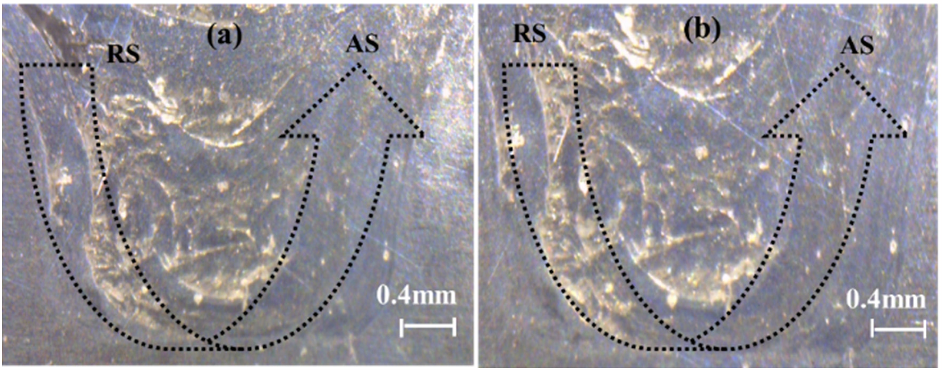
Representation of plasticized material flow (from RS to AS) through optical macrograph (a) T-1 (b) T-2. The direction of the arrow represents the flow of material.

Optical micrographs representing the distinct microstructural zones formed during FSP (a) untreated Al6061 alloy (b) stir zone (sz) (c) thermo-mechanically affected zone (TMAZ) (d) heat-affected zone (HAZ).
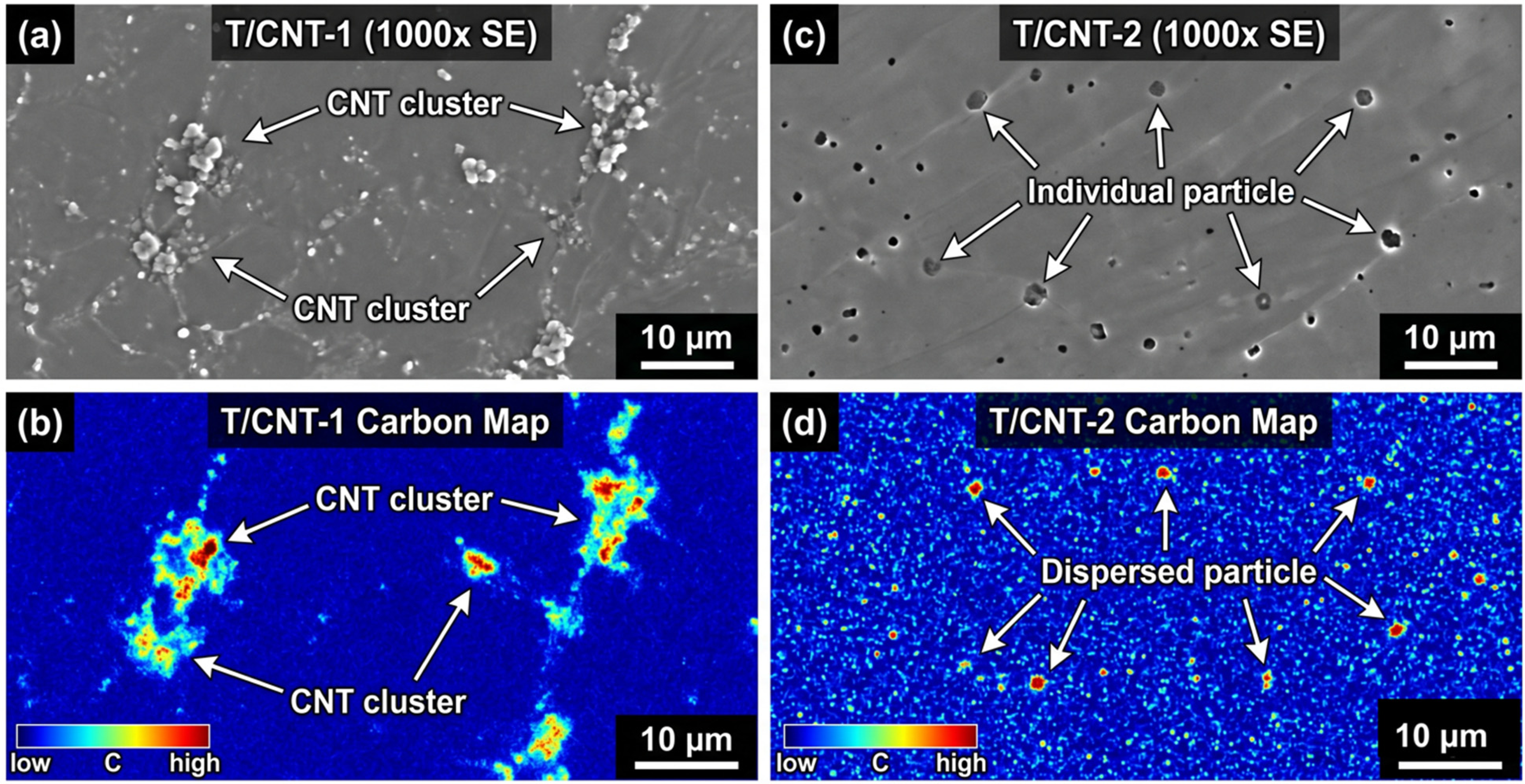
SEM-EDS figure showing the distribution of CNT in the stir zone for two samples. (a): T/CNT-1 (b) EDS carbon map for T/CNT-1 (c) T/CNT-2 (d) EDS carbon map for T/CNT-2.
Raman spectroscopy
Figure 8 illustrates the Raman spectral characteristics of CNTs-reinforced processed samples. The presence of D and 2D bands confirms the retention of CNTs within the MMC. The G-band arises owing to the in-plane stretching of sp2-bonded carbon atoms, while the D-band depicts the defect-induced disorder in the carbon lattice. 27 The observed reduction in G-band intensity in the CNTs-reinforced MMC after processing can be correlated with distortions in the sp2-bonded C–C honeycomb lattice, indicating structural modifications (Figure 8(b)). The elongation of C–C bonds generates substantial structural strain within the crystal.32,33 The same has been confirmed through XRD plot, where different peaks are obtained after FSP. Indeed, the ID/IG ratio can be considered as a direct and quantitative measure of defect density in the sp2-carbon lattice. The rise in the ID/IG ratio from 0.74 (raw CNT powder) to 0.78 (T/CNT-1) and 0.87 (T/CNT-2) points towards a higher density of structural defects in the CNT material—mainly due to Stone-Wales defects, vacancies, and bond rotations—caused by severe plastic deformation through FSP processing. These structural defects, although harmful, form highly reactive carbon edge sites that reduce the energy required for carbon smearing through fretting contact. It becomes easier for these active carbon edge sites to form a CNT tribofilm during fretting wear, hence providing lubrication to the composite. Another parameter, IG/I2D, which is indicative of sp2-lattice strain, drops from 1.56 (raw CNT powder) to 1.51 (T/CNT-1) and 1.19 (T/CNT-2). The lower IG/I2D ratio in the CNT-reinforced Al6061 composite after FSP is primarily attributed to strain-induced distortion of the sp2-bonded carbon lattice relative to the raw CNT powder. It is evident that the sp2-lattice strain induced by FSP, progressively increases with the number of FSP passes. As a consequence, the probability of layer sliding between layers in the carbon structure becomes more pronounced, thus reducing the activation energy required for carbon-layer exfoliation under fretting wear.
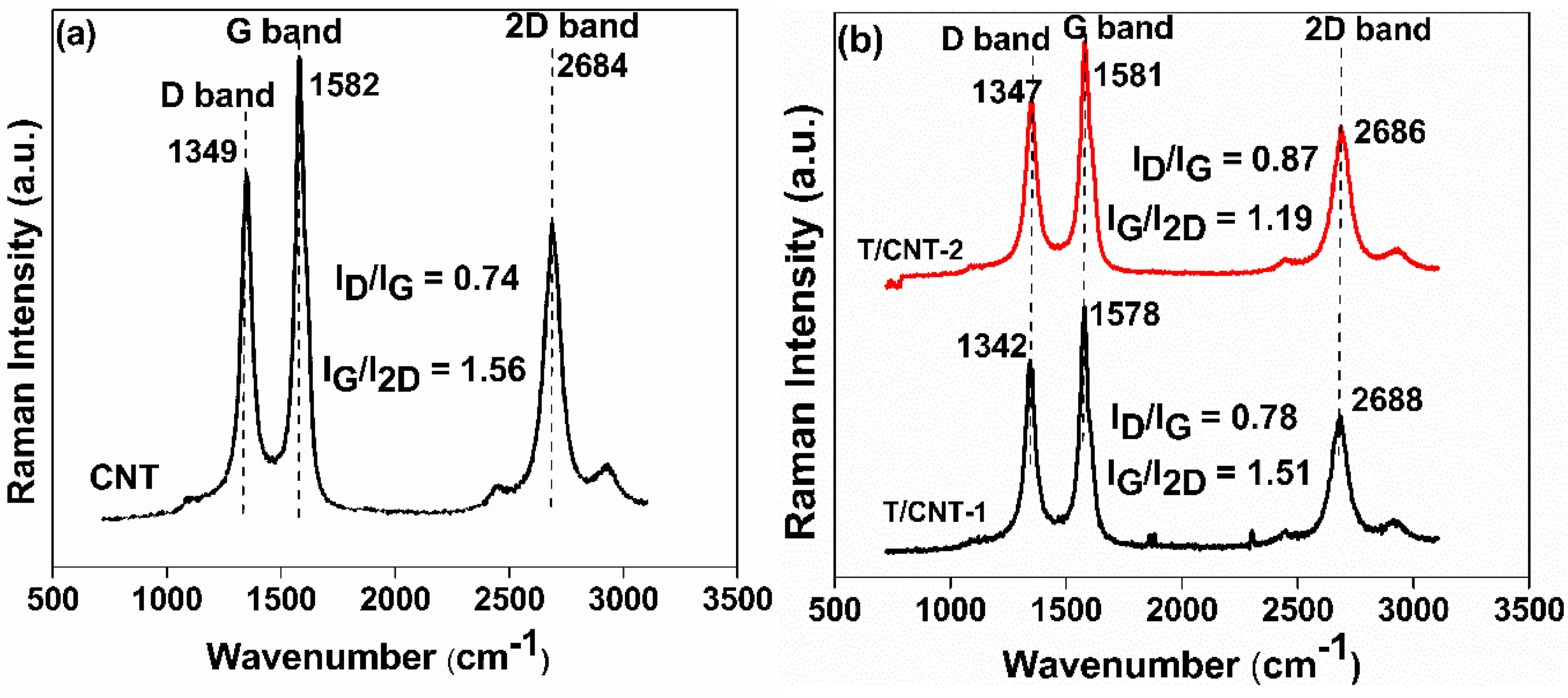
Raman spectra of (a) raw CNT powder (b) CNT-reinforced Al6061 composite.
Micro and nano hardness analysis
Vickers microhardness testing (10 gf, 12 s dwell) was used to assess the hardness behaviour across the stir zone (Figure 9(a)). The microhardness profile shows an asymmetric distribution across the stir zone, with the maximum microhardness observed near the advancing side, attributed to pilling of materials on the advancing side (Table 3).34,35,36 The hardness profile demonstrates a substantial improvement in hardness after the friction stir processing, reaching ∼ 107.40 HV (T-1) and ∼ 110.42 HV (T-2), compared to ∼ 62.87 HV for the untreated material (O), primarily due to grain refinement. The 96.5% increase in the microhardness in the case of T/CNT-2 (123.57 HV) compared to that of the basic alloy (O) correlates well and even exceeds the results obtained by Maurya et al. 27 for carbon-based Al6061 subjected to FSP (∼ 80% increase using graphene) and by Feroz Ali et al. 19 for AA7055/W nanocomposites subjected to multi-groove FSP. For the nanoindentation test, an average of 12 indents was performed on each sample at a peak load of 500 μN, with a holding time of 2 s at peak load. For the untreated sample (O), the elastic modulus and nano-hardness were 54.66 GPa and 1.23 GPa, respectively, which increased to 85.48 GPa and 1.91 GPa after two passes of the process, respectively (Figure 9(b)). Furthermore, the incorporation of CNT reinforcement significantly improved the elastic modulus and nano-hardness, attaining maximum values of 137.27 GPa and 5.34 GPa, respectively, for the CNT-reinforced metal matrix composite processed with two FSP passes. The enhanced hardness and elastic modulus of the MMC are correlated with crystallite size reduction due to FSP-induced grain refinement (Table 2).
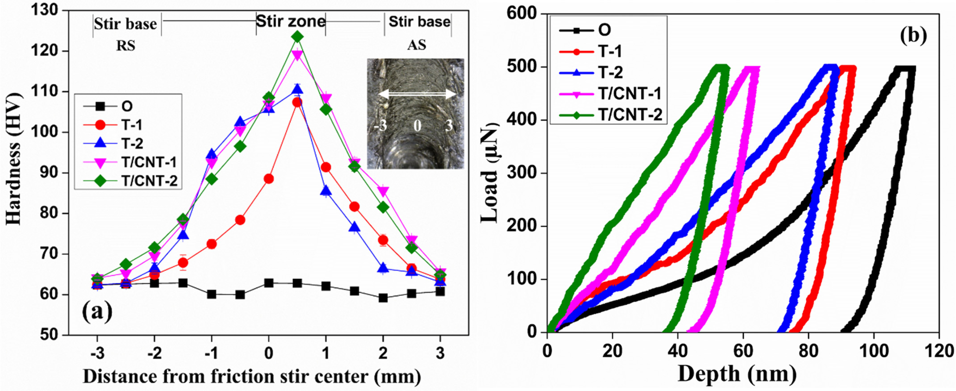
(a) vickers hardness value for friction stir processed and untreated samples (using origin as friction stir center) and (b) plot of load against displacement for friction stir processed and untreated samples.
Mean vickers hardness comparison: advancing side vs. retreating side
Fretting wear surface morphology through SEM analysis
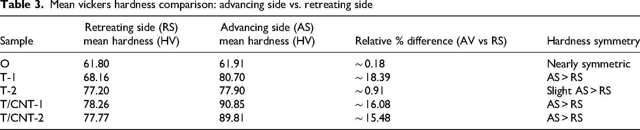
The fretting wear characteristics of friction-stir-processed and unprocessed samples were assessed using a friction wear monitor (TR281 M) integrated with Winducom 2006 data-acquisition software. An investigation of fretting wear was conducted using a stainless-steel ball of 6 mm diameter under controlled test conditions, comprising an oscillation frequency of 5 Hz, a stroke length of 100 μm, 104 cycles, and a constant applied load of 5 N. Figure 10 illustrates the worn surface morphologies of the untreated Al6061 alloy (O), friction stir-processed samples (T-1 and T-2), and CNT-reinforced MMCs (T/CNT-1 and T/CNT-2), as observed by SEM. The untreated material exhibits pronounced wear debris due to direct asperity interactions, facilitating a three-body abrasive wear mechanism along with surface delamination (Figure 10(a)). These factors result in an elevated wear volume (∼ 0.2427× 10⁻³ mm3) and an unstable coefficient of friction (∼ 0.80) in the untreated material. In contrast, samples treated with varying tool passes (T-1 and T-2) exhibit reduced wear debris due to the formation of refined equiaxed grains, leading to lower coefficients of friction (0.75 and 0.71) and higher hardness values (107.40 HV and 110.42 HV, respectively). Through SEM analysis of the worn surface, a cracked tribolayer was also observed in sample T-1, which is mainly due to cyclic stress. 36 Further, CNT-reinforced composites processed with one and two passes predominantly exhibit adhesive wear, resulting in low wear loss (∼ 0.0613 × 10⁻³ mm3 and ∼ 0.0531 × 10⁻³ mm3, respectively) and minimal surface delamination (Figure 10(d), e). As wear progresses, CNTs are pulled from the matrix and dispersed along the interface, forming a carbon-rich tribofilm that mitigates metal-to-metal contact and stabilises the COF at ∼ 0.51 (Figure 12). Elemental mapping of the fretted wear surfaces further supports this mechanism (Figure 11) . Tribocorrosion of wear debris plays a critical role in fretting-induced damage, wherein lower-hardness surfaces generate greater debris, which subsequently oxidises and promotes surface degradation through three-body abrasive wear. In contrast, tribo-oxidation is predominantly an adhesive mechanism that limits oxidation of the tribolayer on contoured surfaces.27,36 Elemental mapping of the worn surfaces reveals extensive damage in the untreated sample (O) (Figure 11(a), (b), (c)). Nonetheless, using CNTs as reinforcements largely mitigates these types of damage. This characteristic limits the unrestricted development of wear debris during fretting and suggests that the heat developed during fretting is insufficient to form an oxide. Therefore, the damage resistance provided by CNTs in FSP Al6061 may be responsible for the improved resistance to fretting through adhesive smearing.
SEM micrographs of worn surfaces during fretting wear (a) O (b) T-1 (c) T-2 (d) T/CNT-1 (e) T/CNT-2.

SEM images of fretting wear surface, taken at constant load of 5 N, stroke length of 100 μm, and oscillating frequency of 5 hz, (a, b, c) O, (d, e, f) T-1, (g, h, i) T-2, (j, k, l) T/CNT-1, (m, n, o) T/CNT-2. Arrows show the direction of fretting.
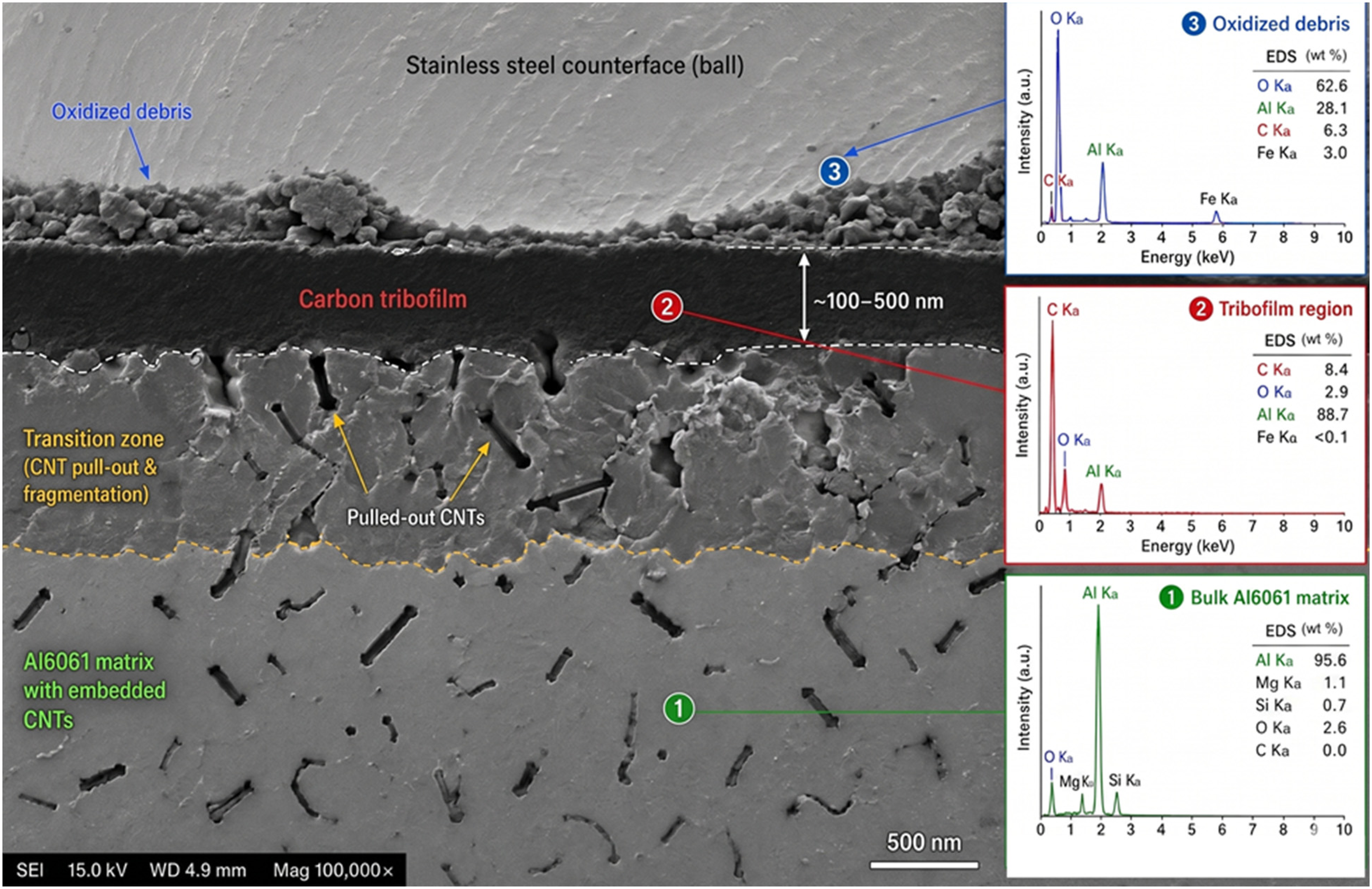
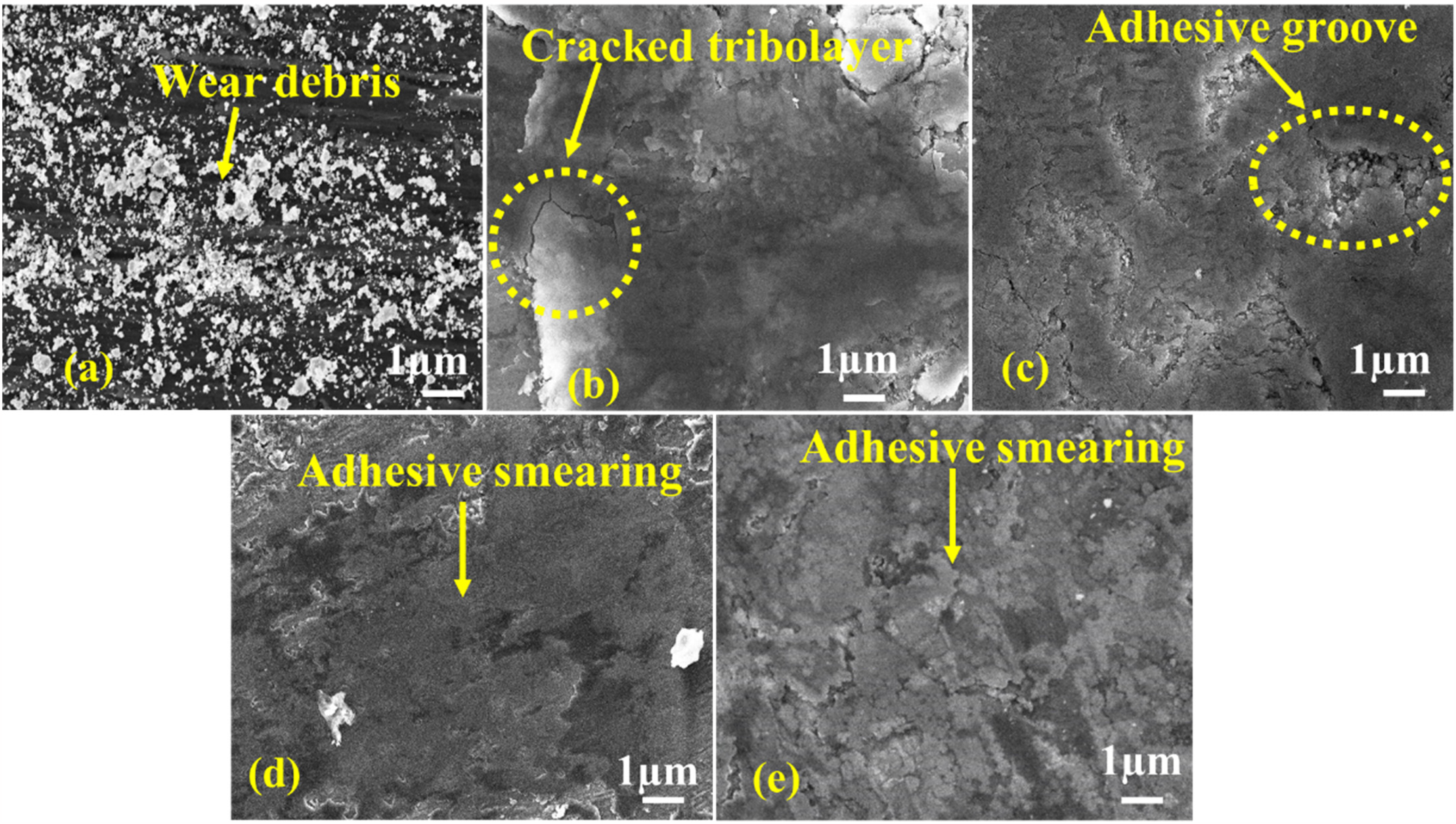
Cross-sectional SEM image showing the tribofilm architecture at the wear interface of the T/CNT-2 sample.
Cross-sectional analysis of tribofilm
CNTs-reinforced composites (T/CNT-1 and T/CNT-2) predominantly exhibit an adhesive wear mechanism, with low wear loss (∼ 0.0613 × 10⁻³ mm3 and ∼ 0.0531 × 10⁻³ mm3, respectively) and minimal surface delamination (Figure 10(d), e). The dominance of adhesive wear despite enhanced hardness may appear contradictory to classical Archard wear theory; however, this is reconciled mechanistically by CNT-mediated tribofilm formation. As fretting progresses, the cyclic contact stress pulls CNTs out of the Al matrix and smears them across the contact interface (Figure 12). The structurally pre-damaged CNTs (evidenced by elevated ID/IG ratios) exfoliate more readily under contact stress, forming a continuous carbon-rich tribofilm. This carbon–carbon adhesive interface effectively reduces friction and wear, despite macroscopic features that suggest adhesive wear. EDS elemental mapping provides direct evidence of carbon enrichment at the wear interface, with carbon atomic percentage increasing to ∼ 8.4 wt.% (T/CNT-2), confirming progressive tribofilm development. The tribo-oxidation products (oxygen-rich regions in Figure 11) are predominantly confined to the untreated sample (Figure 11(a), (b), (c)), supporting the conclusion that CNT-reinforced tribofilm inhibits oxidative wear by limiting metallic surface exposure to atmospheric oxygen (Figure 11 m, n, o).
COF and wear volume analysis
Figure 13(a) shows that the coefficient of friction initially enhances owing to asperity interactions and stabilizes after ∼1000 cycles as dynamic equilibrium is achieved.36,37 COF stabilization at ∼ 1000 cycles is attributed to the establishment of a continuous CNT-based tribofilm at the contact interface. Initially, asperity-dominated metallic contact causes fluctuating friction, which transitions to a steady state as CNTs are extracted and smeared to form a lubricious layer (Figure 12). A dynamic balance between tribofilm formation and removal sustains this behaviour, consistent with the stabilization of the fretting hysteresis loop indicating gross-slip conditions (Figure 14). Further, CNT-reinforced samples (T/CNT-1 ∼ 0.55 and T/CNT-2 ∼ 0.51) show a marked reduction in COF compared to the untreated sample (O ∼ 0.80), consistent with trends investigated in previous studies.4,5,8,18,27 Figure 13(b) shows a significantly higher wear volume for the untreated sample (O ∼ 0.2427 × 10⁻³ mm3) compared to the CNT-reinforced sample processed with two passes (T/CNT-2 ∼ 0.0531 × 10⁻³ mm3). The decreased wear in the CNT-reinforced composite is correlated to its higher microhardness and lower coefficient of friction.
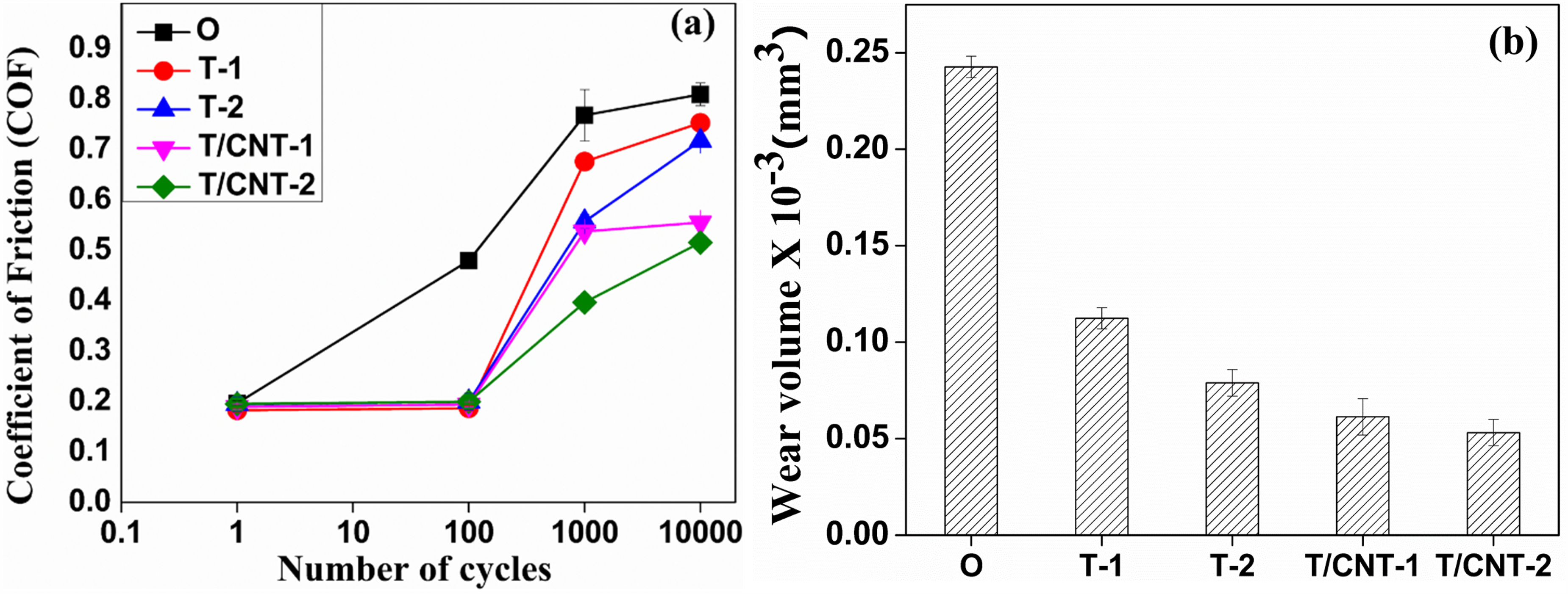
(a) COF plot against number of cycles (oscillating frequency of 5 hz, stroke length of 100 μm, 104 cycles, and under a constant load of 5 N) (b) wear volume representation of untreated and FSP samples.
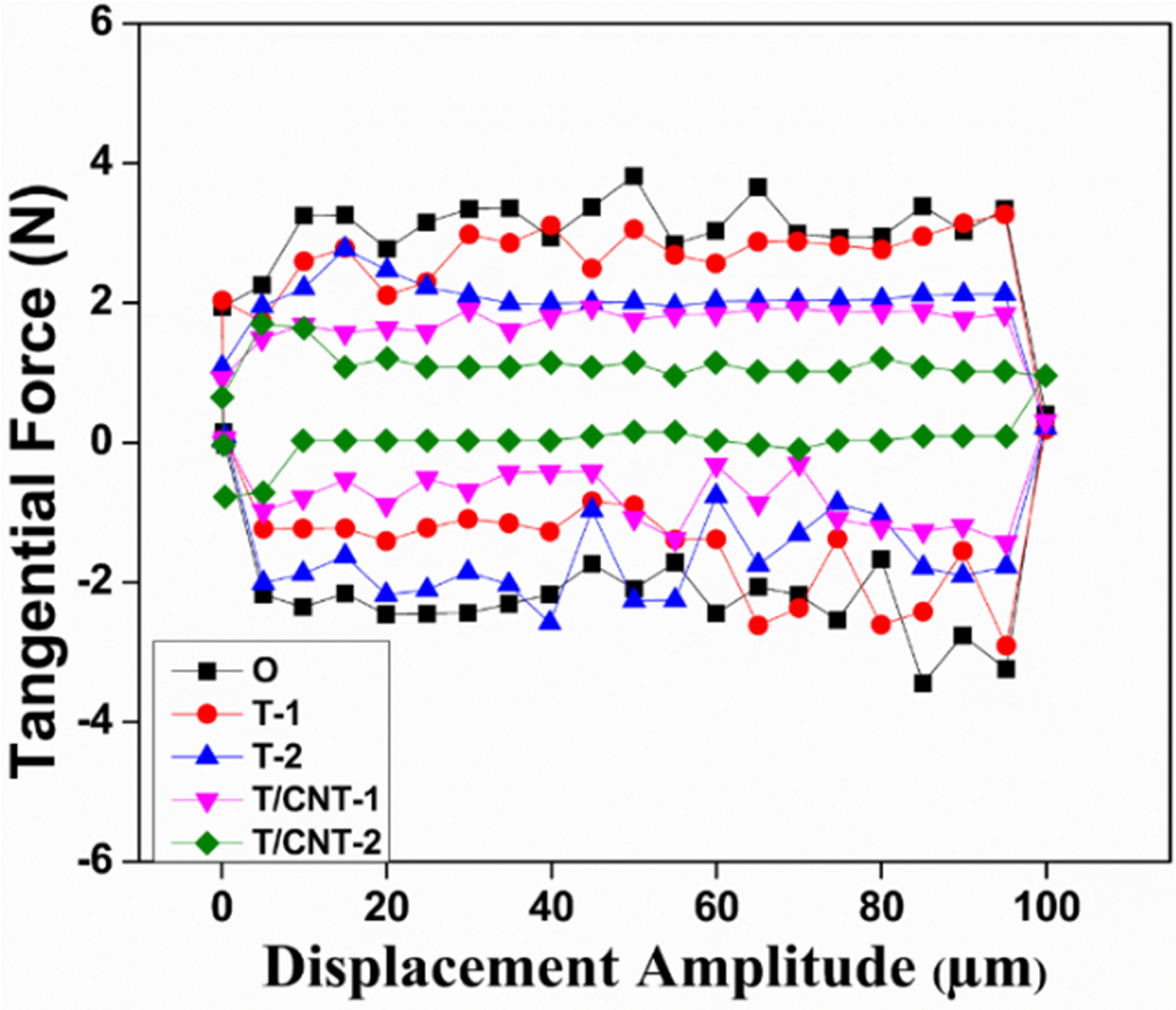
Fretting hysteresis loop taken at a constant load of 5 N, stroke length of 100 μm, and oscillating frequency of 5 hz.
Fretting hysteresis loop
Figure 14 illustrates the plot of tangential load (Ft) as a function of slip amplitude (δ). The wavy circumferential profile observed in the fretting hysteresis loop arises from the sticking behaviour that persists across the entire stroke length.
36
The enclosed area within the hysteresis loop represents the dissipated energy per cycle, which is either accumulated in the workpiece or dissipated as heat.38,39 The fretting hysteresis loop area is evaluated using 
In the above-mentioned equation, μ denotes the COF, and N is the applied load. Swaminathan and Gilbert
40
have expressed the energy dissipated per fretting cycle as: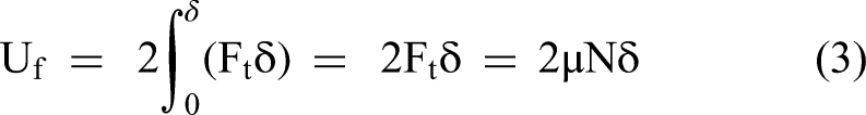
To represent the reciprocating behaviour inherent in fretting wear, a factor of two has been considered, as indicated in Eq. 3. Further, in the mentioned equation, δ represents the displacement amplitude. The fretting hysteresis loop characterises the energy dissipation behaviour during fretting. In addition to optimizing CNT dispersion in the composite, varying passes of the friction stir processing (FSP) technique enhance tribofilm stability through three distinct mechanisms. The first of them is associated with the finer distribution of CNT particles as a result of using multiple FSP passes (the CV of CNTs is ∼ 8% in the case of T/CNT-2, as opposed to CV ∼ 12% for T/CNT-1), which provides for more source sites for tribofilm formation in the contact zone. 31 The second effect relates to increased damage to the CNT structure, as revealed by Raman spectroscopy (ID/IG ∼ 0.87 for T/CNT-2 and ∼ 0.78 for T/CNT-1), which enhances their reactivity and reduces the energy expenditure for tribofilm generation in the fretting contact area. The third effect is associated with a smaller crystallite size (∼ 24 nm) obtained by multi-pass FSP, providing a smoother subsurface microstructure and, hence, improved tribofilm adhesion at the wear surface. Consequently, the synergistic contribution of the aforementioned mechanisms results in the formation of a more thermally stable, continuous, and well-adhered tribofilm in the T/CNT-2 composite compared to T/CNT-1, which translates into improved tribological performance, reflected by a lower coefficient of friction (0.51 vs. 0.55) and diminished wear volume (0.0531 × 10⁻³ mm3 vs. 0.0613 × 10⁻³ mm3). The shape of the hysteresis loop provides diagnostic information about the wear regime: A narrow, rectangular/parallelogram loop indicates gross-slip behaviour with low energy dissipation per cycle, characteristic of an effective tribofilm; a wider, elliptical loop would indicate partial-slip or stick-slip behaviour with higher energy dissipation. The T/CNT-2 sample exhibits the narrowest hysteresis loop (Uf = 5.1 × 10⁻⁴ J/cycle), confirming that the self-lubricating carbon tribofilm maintains gross-slip conditions with minimal tangential force variation, thereby reducing cyclic surface damage. The 36% reduction in dissipation energy (from 8.0 × 10⁻⁴ J/cycle to 5.1 × 10⁻⁴ J/cycle) corresponds mechanistically to: (a) reduced COF (Δμ ∼ 0.29, contributing ∼ 36% directly via the Uf = 2μNδ relation), which is consistent with the observed COF reduction from 0.80 to 0.51, confirming that the reduced energy dissipation is primarily driven by the tribofilm-mediated friction reduction rather than changes in contact geometry or stroke length. This quantitative consistency supports the proposed mechanistic mode.
Role of multi-pass FSP in tribofilm stability
Apart from optimising the distribution of CNTs, multi-pass FSP also increases tribofilm stability in two ways. Firstly, due to the greater level of damage of the CNT structure in T/CNT-2 (ID/IG = 0.87) compared to T/CNT-1 (ID/IG = 0.78) observed via Raman spectroscopy, the reactivity of carbon edge sites increases, reducing the energy required for forming a tribofilm at the fretting contact point. Secondly, the smaller crystallite size formed during multi-pass FSP (∼ 24 nm) resulted in a smoother subsurface microstructure, favouring the adhesion of the tribofilm at the wear interface. All the effects mentioned above ensure that the tribofilm in T/CNT-2 has better thermal stability, continuity, and adhesion compared to the film formed in T/CNT-1 composite, which makes its tribological properties significantly better (COF ∼ 0.51 vs. 0.55; wear volume ∼ 0.0531 × 10⁻³ mm3 vs. 0.0613 × 10⁻³ mm3).
Conclusions
Al6061 alloy was subjected to two-pass FSP to introduce and uniformly disperse CNTs as reinforcement. The following conclusions are drawn:
XRD peak indexing confirmed the presence of Al and Al–Fe–Si precipitates. The absence of Al4C3 peaks confirms that no detrimental interfacial reaction occurred during FSP, preserving CNT structural integrity. Raman spectroscopy confirmed the retention of carbon nano tubes in the metal matrix. The progressive increase in the ID/IG ratio (0.74 → 0.87) with increasing FSP passes indicates FSP-induced structural damage to CNTs, which is mechanistically linked to enhanced tribofilm-forming reactivity. The corresponding reduction in the IG/I2D ratio confirms lattice-strain accumulation, promoting carbon-layer exfoliation under fretting-contact stress. A remarkable decrease in crystallite size was observed (T/CNT-2 ∼ 24 nm vs. O ∼ 47 nm). Quantitative analysis shows that crystallite refinement accounts for ∼ 51% of the observed wear reduction, while CNT-mediated tribofilm formation contributes the remaining ∼ 27%, demonstrating the synergistic nature of the tribological improvement. The CNT-reinforced composite demonstrates ∼ 96% enhancement in microhardness (T/CNT-2 ∼ 123.57 HV), ∼ 36% reduction in COF (T/CNT-2 ∼ 0.51), and ∼ 78% decrement in wear volume (T/CNT-2 ∼ 0.0531 × 10⁻³ mm3) relative to the untreated alloy. These values compare favourably with, and in many cases exceed, those reported for CNT- -reinforced Al composites, confirming the effectiveness of the CNT/multi-pass FSP approach. COF stabilisation at ∼ 1000 cycles is governed by the achievement of a steady-state tribofilm coverage, confirmed by the transition to a stable parallelogram-shaped hysteresis loop. EDS elemental mapping confirms carbon enrichment at the wear interface (C: ∼ 8.4 wt.% for T/CNT-2), providing direct evidence of in situ carbon-rich tribofilm formation. The 36% reduction in dissipation energy (5.1 × 10⁻⁴ J/cycle vs. 8.0 × 10⁻⁴ J/cycle) is quantitatively explained by COF reduction via the relation Uf = 2μNδ. The narrow, rectangular hysteresis loop of T/CNT-2 confirms gross-slip behaviour with minimal cyclic surface damage, attributable to the self-lubricating tribo-carbofilm. Multi-pass FSP enhances tribofilm stability through three synergistic mechanisms: (a) improved CNT distribution homogeneity (CV ∼ 8%), (b) increased CNT structural reactivity (higher ID/IG), and (c) finer crystal structure promoting tribofilm adhesion.
Therefore, a multi-pass FSP with CNT reinforcement is recommended as a promising approach to enhance the tribo-mechanical performance of Al6061 alloy for wear-resistant engineering applications.
Footnotes
Acknowledgments
Authors acknowledge the CIM lab of GLBITM, Greater Noida, for performing friction stir process experiments.
Author contribution(s)
Funding
The authors received no financial support for the research, authorship, and/or publication of this article.
Declaration of conflicting interests
The authors declared no potential conflicts of interest with respect to the research, authorship, and/or publication of this article.
Data availability
The data that support the outcomes of this study can be obtained upon reasonable request.