
Abstract
Motivated by the requirements of mobile manipulation, a compliant underactuated hand, capable of locking individual joints, has been developed. Locking is accomplished with electrostatic brakes in the joints and significantly increases the maximum pullout forces for power grasps. In addition, by locking and unlocking joints, the hand can adopt configurations and grasp sequences that would otherwise require a fully actuated solution. Other features of the hand include an integrated sensing suite that uses a common transduction technology on flexible printed circuits for tactile and proprioceptive sensing. The hand is analyzed using a three-dimensional rigid body analysis package with efficient simulation of compliant mechanisms and contacts with friction. This package allows one to evaluate design tradeoffs among link lengths, required tendon tensions, spring stiffnesses and braking requirements to grasp and hold a wide range of objects. Results of grasping and pullout tests confirm the utility of the simulations.
1. Introduction
Although advanced multifingered hands have been a research topic for over 30 years, advances in energy storage, actuation, sensing computation and control are leading to a renewed focus on hands for mobile platforms. A related subject is advanced prosthetic hands. In either case, mobile manipulation imposes special requirements on hand design and operation.
Foremost, it is important to reduce mass in comparison to hands or grippers on stationary arms. Mobile manipulator arms are often lighter, less rigid and furnished with smaller motors than a grounded arm. The motors must accelerate the hand and balance the gravity torques that it creates. Springs or other counterbalancing measures are possible, but they add weight and complexity, and are rarely used.
Given that hands will often be the fastest moving parts of the robot, the inevitability of collisions places a premium on robustness. Robustness is enhanced through a combination of impact-resistant materials and compliance. Having back-drivable actuation is also helpful to absorb unexpected external forces without damaging transmission elements. Underactuated mechanisms are inherently tolerant of unexpected contact forces, as the interaction force can be redistributed among the parallel elements of the underactuated system.
With mobile manipulation there is also a premium on reducing energy consumption, especially when the platform is powered by batteries. In this case, having back-drivable actuation can be a disadvantage, unless there are springs or brakes. The desire to reduce grasping effort also leads to using gripping surfaces with compliance and a high coefficient of friction.
Other considerations arise from the types of objects that hands designed for mobile manipulation are expected to grasp, and the types of manipulations performed. At present, the focus is on power grasps, i.e. on holding objects securely in the hand and imparting external forces and motions via the arm and wrist. However, certain within-hand manipulations may be desirable. For example, the grasp initially used for acquiring a small tool may be a fingertip pinch, which should evolve to an enveloping wrap when working with the tool to accommodate larger forces and torques, or to permit a larger configuration space that better utilizes the kinematics of the arm and wrist (Cutkosky, 1989). Another example is holding a power tool in a wrap grasp while having the ability to depress a trigger or power button (Figure 1, lower right).
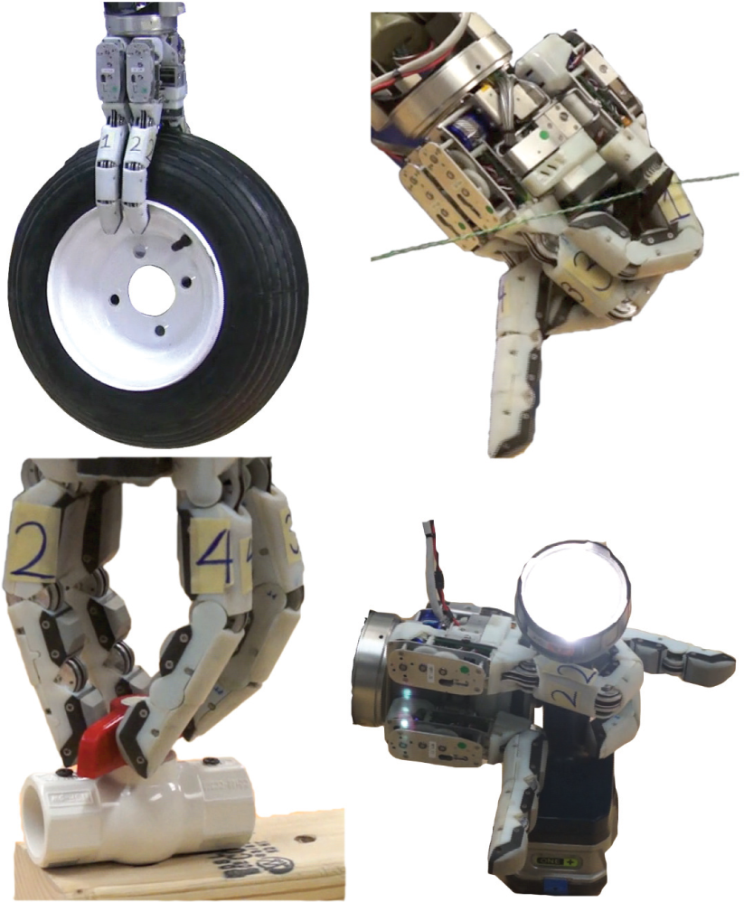
The SRI Hand using various grasps, some with locked joints, to carry a heavy tire, clip a wire with cutters, open a valve and turn on a flashlight.
Hands on mobile platforms are also expected to work in partially unstructured environments. Hence they cannot expect that objects and tools will be presented to them in fixtures that facilitate object acquisition. The robots will instead use vision to identify objects on table tops or on the ground, and the hand will need to acquire them.
The foregoing considerations were at the heart of the recent DARPA ARM-H challenge 1 and provide the primary motivation for the hand design and the object acquisition and pullout analyses presented in this paper.
2. Related prior work
Dexterous robotic hands have been a perennial research topic, starting with a three-fingered hand with 11 actuated degrees of freedom by Okada (1979). Many subsequent hands and design considerations are reviewed in Venkataraman and Iberall (1990), Bicchi (2000), Bicchi and Kumar (2000), and Melchiorri and Kaneko (2008). Recently, the DLR Hand-Arm system (Grebenstein et al., 2012), with 52 actuators, 19 degrees of freedom in the hand and integrated variable-stiffness devices, has pushed today’s limits of packaging, power, and control. Along the way, the field of underactuated hands has branched off, with specialized designs and analysis tools that build upon the literature in dexterous manipulation and address special concerns that arise with systems for which individual joint torques cannot be specified a priori.
2.1. Underactuated hand designs and technologies
Underactuated hands span a spectrum of conceptual approaches (Birglen et al., 2008). At one end of the spectrum are highly underactuated (Hirose and Umetani, 1978; Laliberté et al., 2010) and highly compliant designs (Dollar and Howe, 2006, 2010) that use a single actuator for many links. These designs are particularly focused on being able to conform to a wide range of objects and hold them securely. At the other end are hands which are designed to lock up and hold objects rigidly once the fingers have made contact (Gosselin and Laliberté, 1998; Montambault and Gosselin, 2001; Laliberté, 2003). Some commercial hands (e.g. Barrett, 2 Robotiq, 3 H2H, 4 and Fetch 5 ) also use underactuation to achieve a wider range of grasps than would otherwise be possible.
A number of underactuated hands also incorporate special mechanisms to increase their versatility for different grasping scenarios. Such mechanisms are often much more compact than servomotors with transmissions and can therefore be incorporated directly into the fingers. Arai and Tachi (1991) use brakes to couple phalanges together as they accelerate, unlocking them so that their momentum allows them to dynamically wrap around objects. The Barrett hand uses a clutch with a programmable slip torque (Ulrich et al., 1988). Takaki and Omata (2006) demonstrate joint locking with a torsion spring that holds 2.5–5.0 Nm when braking, and use a shape-memory alloy wire to set and release the brake. The Twix Hand (Begoc et al., 2007) utilizes a check valve – the pneumatic analog to a ratchet mechanism – to kinematically constrain its fingers in a pinch unless contact occurs on the first phalanx. Variable transmission-ratio devices were implemented in the designs of Takaki and Omata (2006) and Spanjer et al. (2012), and variable preload devices are investigated in Aukes et al. (2011). Willow Garage’s “Velo 2G” gripper 6 uses spring preloads to maintain a position constraint which keep fingertips parallel to each other, similar to the linkage-based design discussed in Birglen (2011). Catalano et al. (2012) designed a hand with stiffness and drive train selected to reflect identified “adaptive synergies”, while allowing the hand to fail gracefully in the case of disarticulations.
2.2. Analysis and design methods
Designing an underactuated hand typically involves making some initial discrete choices among numbers and arrangements of fingers, types of actuators, etc., followed by parametric variations involving link lengths, transmission ratios, joint ranges, spring constants, etc. For the former choices, methods such as kinematic-type synthesis (Birglen, 2009) and automated search among different topologies using measures of grasp quality are applicable (Hammond et al., 2012). Exploiting recognized hand or grasp synergies can also be valuable to reduce the very large search space (Ciocarlie and Allen, 2009b; Bicchi et al., 2011; Gabiccini et al., 2011).
Having chosen a basic hand configuration, many tools are available for hand analysis and parametric optimization. Birglen et al. (2008) provide a general framework for describing the kinematics and forces for compliant, underactuated robotic hands. Balasubramanian and Dollar (2011) investigate the optimal number and placement of actuators in a representative underactuated system. Other investigations (Ciocarlie and Allen, 2009a; Dollar and Howe, 2010; Ciocarlie and Allen, 2011; Dollar and Howe, 2011) explore variations in compliance and link lengths for underactuated hands, which determine the range of objects that can be acquired and held securely. The effects of secondary actuation, for example to vary internal stiffness or to lock certain joints, have also received attention (Demers and Gosselin, 2009; Aukes et al., 2012).
2.2.1. Numerical simulation
Dynamic simulation has evolved to provide robust, stable solutions to problems with intermittent contact, friction, and joint limits. Anitescu and Potra (1997) developed a fixed-timestep approach for solving such problems as a linear complementarity problem (LCP) with friction. Stewart and Trinkle (2000) also used LCP methods, but with an impulse formulation that treats contacts as instantaneous events, guaranteeing convergence of certain problems where force formulations fail. Miller and Allen (2004) developed a dynamic simulation program for GraspIt! that incorporates the general framework laid out by Anitescu and Potra, modeling Coulomb friction with an approximate friction cone. GraspIt! has since become a widely used tool for evaluating grasps. Ciocarlie and Allen (2011) illustrated the use of GraspIt! to optimize the design of a class of underactuated hands as a quadratic programming problem. Drumwright (2011) explored alternate formulations to the LCP problem, developing a quadratic program with equivalent accuracy and improved efficiency. This formulation is included in Moby, 7 an impulse-based rigid-body dynamics simulator, which is used for the simulations employed in Section 4.
3. ARM-H Hand description
The SRI selectively compliant underactuated hand was designed to meet the requirements of the DARPA ARM-H challenge of a robust, versatile and low-cost hand for mobile manipulation. The main elements of the hand are described in the remainder of this section. Hand analysis and testing are covered in the following sections. Extension 1 shows several aspects of the hand in more detail.
The hand is composed of four identical finger modules connected to a main driver board located inside the palm unit. Each finger module consists of an Exceed RC 2210–1080 kV brushless DC outrunner motor rewound in a Wye configuration, with the motor output connected to a 50:1 two-stage spur gear transmission terminating in a pulley. Braided 70-lb Spectra line is wound around the pulley and threaded into the fingers. The resulting maximum sustained tendon tension is 150 N, but tendon tensions are limited to 50 N in operation.
A custom motor driver board located in each finger module is equipped with optical encoder feedback and a single-axis 10 kg micro load cell (MLC700, ManyYear Technology Corp.) for operating in position, force or stiffness control. The finger modules require both communication and power connections to the main driver board.
In the palm, two additional motors are used to reposition two of the fingers using a slide and lead screw. In the middle of the travel, a plate forces the spring-loaded fingers into a spherical grasp (Figure 2, middle) before they return to an opposed orientation. This enables the hand to achieve a variety of opposed and interlaced grasps, as each slider motor can be controlled independently.
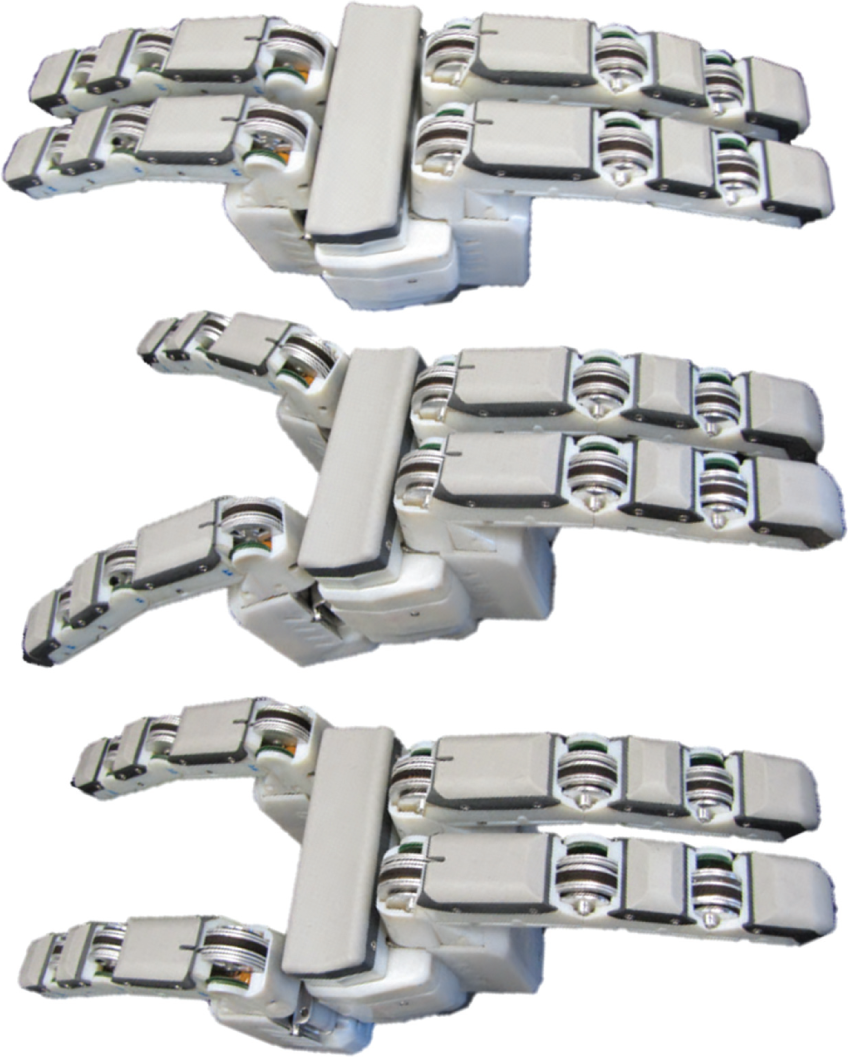
The fingers on the left can move and rotate on a slider mechanism to achieve opposed wrap (top), spherical (middle) and interlaced (bottom) configurations.
3.1. Finger structure
The structure of each phalanx is made of laser-cut aluminum sheet metal. The walls of the structure hold the moving parts, electrolaminate brakes, tendons and springs (Figure 3). Laser-cut holes provide precise locations for joint axes, pulleys, and other rotating elements, while the outer profile defines locating features for the three-dimensional (3D) printed plastic protective shells that cover the outside of the finger. Rubber pads are attached to the inside surface of each phalanx, and provide a high-friction surface. Beneath the pads are tactile sensors, described further in Section 3.3. Bushings are made from brass and steel tubes. Coil springs are placed at each joint to provide a passive opening force. The ends of the springs fit into one of a series of holes to adjust the preload. Joint limits are determined by contours in the outer plastic shells.
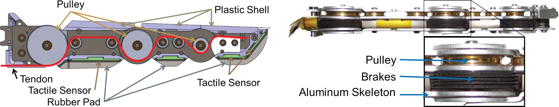
(Left) Rendering of a finger shows tendon routing, pulley sizes, plastic shells, rubber pads and sensors. (Right) Photograph and detail of structure with cover removed, showing electrolaminate brakes, pulleys, and the sheet metal skeleton.
3.2. Brakes
The hand’s capability to lock individual joints is made possible by “electrolaminate” brakes that produce a clamping pressure when high voltages are applied. The brakes are composed of interleaved flexible sheets on which a patterned electrode is printed and covered with a thin dielectric, exhibiting the clamping properties originally noted in Johnsen and Rahbek (1923). The material and thickness of the sheets are chosen empirically to provide a maximum braking torque for a given set of overall dimensions. If the sheets are too thin or soft, they tend to buckle; if they are too thick and stiff, the maximum braking torque is modest. In the present application the sheets are coated kapton and are 250
The braking torque is a function of both the applied voltage and time, as seen in Figure 4(a). In addition, the brakes require a small amount of torque to resume sliding after the voltage is turned off. This release torque is a function of both the amount of time the brake is on and the delay from the time it was turned off to when it was actuated, as seen in Figure 4(b). As a consequence, hand control strategies utilize the brakes mainly to switch between configurations and to reduce the motor torque required in a steady grasp, not for dynamic variations in joint torque.
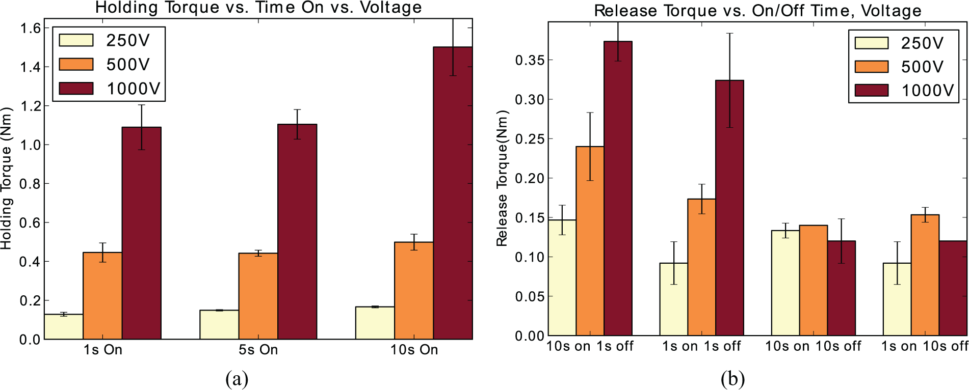
For electrolaminate brakes, time and voltage affect both the maximum braking torque and the torque required to resume sliding after voltage is turned off. Data are for a brake at the proximal joint of a finger, with 12 layers and an outer diameter of 24 mm for the active area.
3.3. Tactile and proprioceptive sensing
In comparison to the hands of animals, robotic hands make do with very few sensors. Conventional tactile, force and proprioceptive sensors are expensive and fragile. Providing wiring to such sensors distributed over the fingers is also a challenge. However, this situation is starting to change with the increasing availability of small and inexpensive sensors and processing chips from the smartphone industry. Recent developments include the TakkTile array from Harvard 8 and capacitive arrays using surface-mounted chips that take care of active shielding, signal processing and digital communications (Cannata et al., 2008; Kaneswaran and Arshak, 2008; Ulmen and Cutkosky, 2010; Heyneman and Cutkosky, 2012).
For the selectively compliant hand it was decided to take advantage of these developments by making the tactile and proprioceptive sensor suite a modular rigid-flex design (Figure 5) using a common capacitive transduction technology based on the AnalogDevices AD7147 capacitance-to-digital converter. A flex circuit bus in each finger has standard connector breakouts for tactile or proprioceptive sensors. This approach reduces wiring and can support larger numbers and densities of sensors in the future. A single transduction technology allows a standard chipset to be repeated at multiple locations, simplifying design and allowing code reuse for different types of sensors.
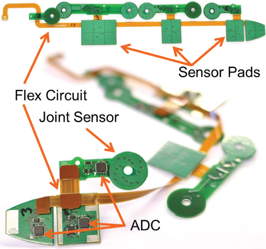
View of the tactile sensor, flexible bus, and rotary joint sensor.
3.3.1. Capacitive tactile sensing
Capacitive arrays are a common solution for tactile sensing (Cutkosky et al., 2008). With attention to materials and construction they can have high dynamic range and low hysteresis, making them suitable for dynamic as well as static or low-frequency measurements. They can also be thin and robust – desirable attributes in a robotic finger.
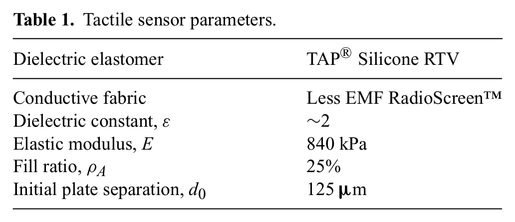
The sensor construction is shown in Figure 6, with a list of design specifications in Table 1. The outer, grounded layer is a silicone rubber sheet with an embedded conductive fabric. The dielectric is a dense array of silicone rubber posts, ~200
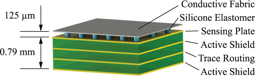
Anatomy of a tactile sensor in the selectively compliant hand.
Tactile sensor parameters.
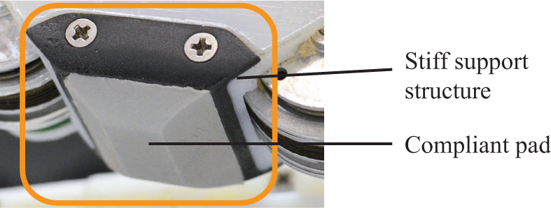
Tactile sensors are protected by a two-part removable urethane cover. The cover consists of a hard backing to provide support, and a soft overmold to make up the finger’s inner surface geometry and add compliance to the grasping surface.
By assuming small displacements and using the standard capacitor plate equation, C = εA/d, where ε is the dielectric constant, and A and d are the plate area and separation, respectively, the change in separation for an applied pressure, p, can be described by

The sensitivity of each site for light pressures is given by
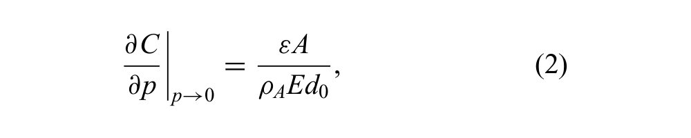
where ρA is the fill ratio of the dielectric posts, ε is the effective dielectric constant of the posts and air gaps, E is Young’s modulus and d0 is the initial height. Thus by adjusting materials, initial thickness and fill ratio, one can tailor the sensor for a desired sensitivity while also making it sufficiently strong to prevent saturation or crushing at maximum anticipated loads.
The hand is fitted with a tactile suite having 96 sensing sites and a 200 Hz sampling rate, utilizing a network of 16 AD7147 chips with 6 sampled locations each site. Each site (0.46–0.99 cm2, 0.8 cm2 average) resolves normal forces with a minimum of ~20 mN (2 g) and a saturation force of ~130 N. As seen in Figure 8, the output is slightly non-linear. Noise limits the effective resolution to ~11 bits at the 200 Hz sampling rate.
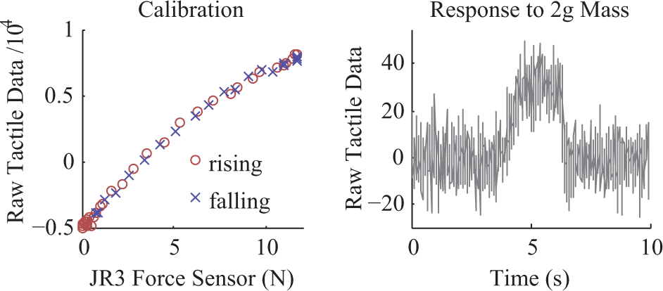
(Left) Tactile sensors are calibrated against a reference force sensor (JR3 Inc. Woodland, CA). (Right) Response of a single tactile sensor to placement and removal of a 2 g mass.
3.3.2. Joint angle sensing
To take maximum advantage of the brakes, the individual joint angles should be known. Common solutions include potentiometers, Hall effect sensors and encoders. In the present case, a compact and low-cost solution is obtained using the same capacitive transduction technology as for the tactile sensors. Capacitive position sensing is widely used, for example, in digital calipers (Gustafsson and Pettersson, 1991). Here, the main challenge is to obtain a high angular resolution for rotations about the joint axis while being relatively insensitive to small motions in the remaining 5 degrees of freedom – particularly important for a low-cost, compliant hand without precise bearings at the joints.
The basic design and operation are depicted in Figure 9. Two patterned layers of conductor are separated by a thin dielectric to form a set of parallel-plate capacitors. The sensing half contains a set of four pads repeated radially N times, with corresponding pads in each set electrically connected. The other plate is also N-fold symmetric and consists of two regions which yield maximum capacitive contrast (ground and the AD7147 active shield) and produce four capacitive measurements in quadrature. The measurements are
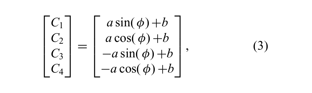
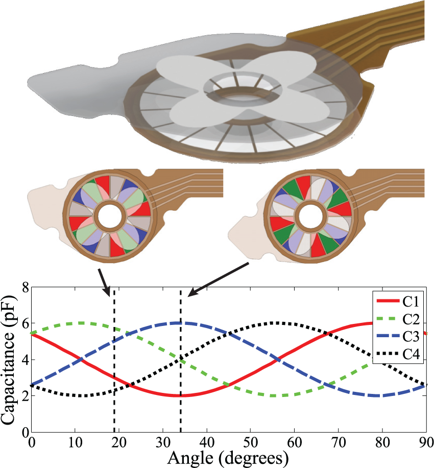
As the joint sensor plates rotate with respect to each other, the capacitance of adjacent conductive pads varies sinusoidally with the rotation angle, at 90° phase increments. The differential signals that result from these four measurements are robust to alignment errors.
where a is the separation dependent amplitude, b is the common bias capacitance (trace routing, etc.), and ϕ is the angle within one electrical period defined by a single set of measurement pads.
From these the encoder angle, θ, is calculated as
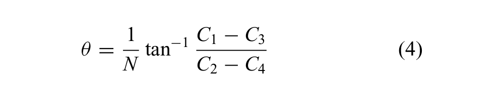
where tan−1 is computed using the two-argument atan2. Combining terms and simplifying results in

in which the first-order dependencies on a and b are eliminated. The factor 1/N is due to the repetition of the sensing pads, and the angle is appropriately unwrapped at the boundaries. The measurement is absolute within one electrical period, but is incremental between periods because angle unwrapping will always return |Δϕ| ≤ π. This places a maximum rotation rate limit of 2π/N rad/sample.
The two halves of the sensor are assumed to be rigid plates and therefore small motions not about the joint axis will increase capacitance on one section while decreasing it on the opposite (through changes in pad/ground overlap or pad/ground separation). The N-fold symmetry of the sensor uses this fact to cancel the first-order effects of these motions by placing electrically connected pads on opposite sides of the sensor.
The sensor was characterized by mounting it on a common shaft with a 10,000 CPR (counts per revolution) US Digital E6 optical encoder as a reference. The shaft and encoders were manually moved through a ~270° rotation and back to the initial position. Two typical trials are shown in Figure 10 (top). In the legend, intentional misalignments are specified as X μm/Y μm where X and Y are radial misalignments of the pads and scale, respectively.
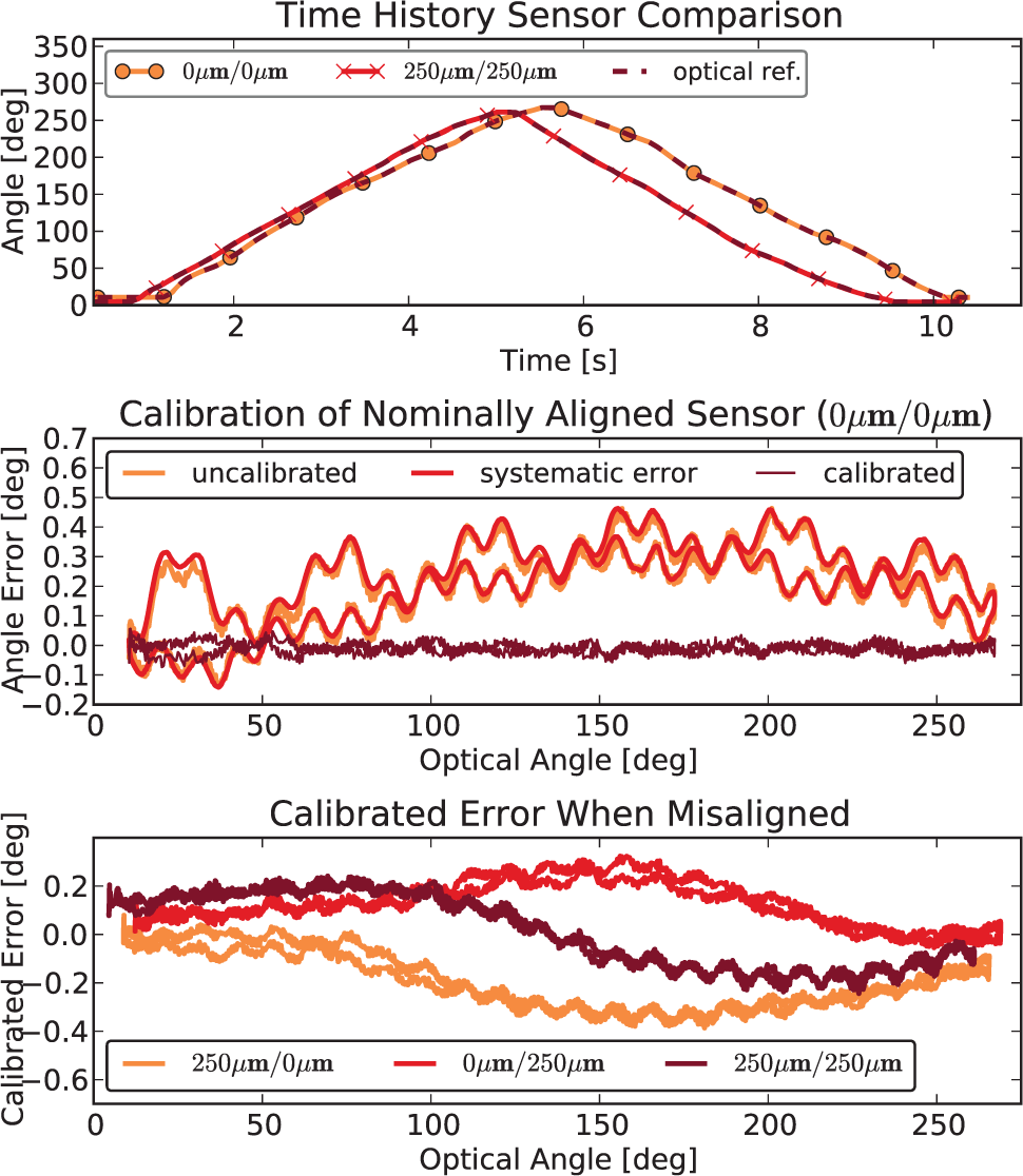
(Top) Typical trials with aligned and intentionally misaligned capacitive encoder. (Center) Calibration removes systematic errors due to velocity effects and deviation from ideal quadrature. (Bottom) Calibration applied to misaligned sensors, revealing the dominant error due to misalignment.
There are a variety of systematic errors expected in a real sensor, including deviation from ideal pad and scale shapes, non-concentric board edge and pad/scale patterns, and the sequential (rather than simultaneous) sampling of the AD7147. These errors can be calibrated on a nominally aligned system. The uncalibrated error, fit to systematic errors, and resulting calibrated error are shown in Figure 10 (center). The periodic and velocity-dependent errors are clearly visible. Such a calibration yields an angular resolution of ~0.16°, or 2250 CPR. In the calibrated signal, periodic errors are still visible, indicating that the total error is dominated by imperfect calibration, not noise.
When this calibration is applied to a misaligned sensor the resulting periodic errors are clearly visible in Figure 10 (bottom). Gross misalignment causes the dominant error with a period of 360°, while the non-ideal pad/scale shapes result in errors with a period of 360°/32 = 11.25° (there are 32 pads on the benchtop version). For reasonable misalignments of the sensing pads and/or scale (250 μ m) the resolution drops to ~ 0.5°, or 720 CPR; more than enough for this application.
The final version of the sensor incorporated into the hand differs from the benchtop test sensor (Table 2). It has been reduced in size, and the number of repetitions, N, has been decreased. Because calibration errors dominate the noise performance of the AD7147, this is expected to result in a decrease in angular resolution and an increase in maximum angular rate.
Capacitive encoder parameters.
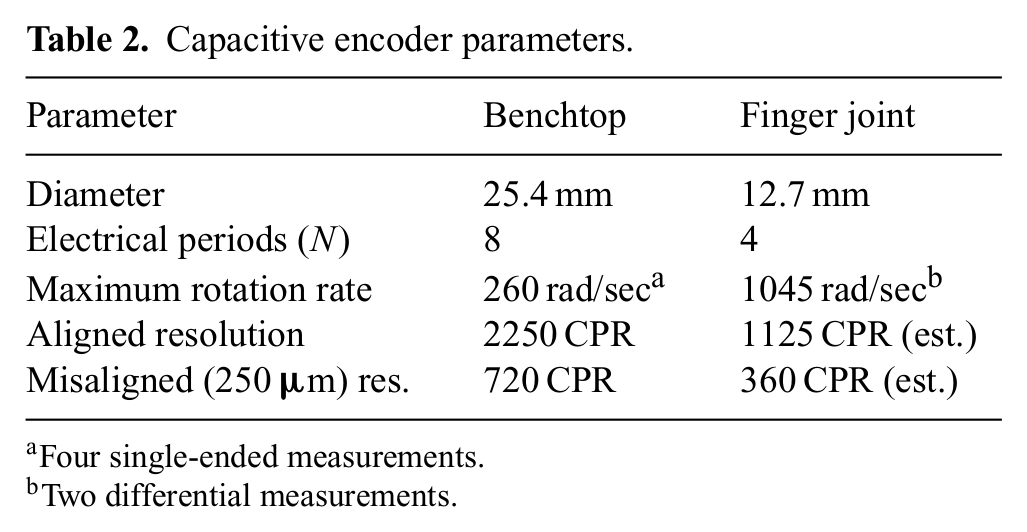
Four single-ended measurements.
Two differential measurements.
4. Analysis of object acquisition and pullout forces
In designing the hand, two primary design objectives were to acquire objects in a wide range of sizes, and to hold heavy objects without excessive motor torques. By deriving the equations of motion, the relationship between design parameters and the hand’s capacity to hold objects can be studied across various designs and in interesting loading configurations. These equations can assist in providing design guidance for components like the transmission ratios, springs, and electrostatic brakes.
4.1. Kinematics and contact
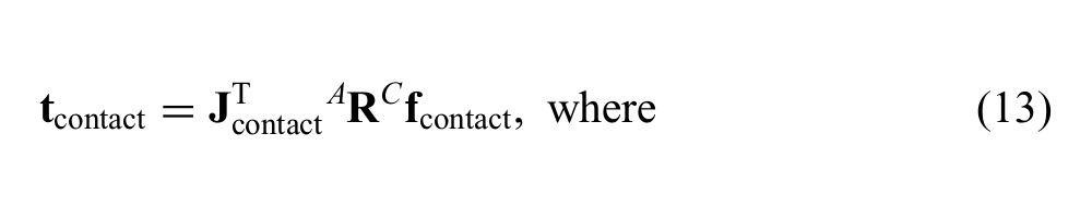
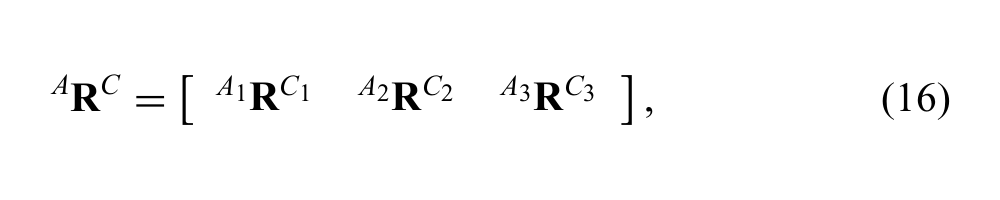
To derive the equations of motion, transforms that map various forces acting on the hand into joint space must first be derived. The palm is fixed in the Newtonian frame N, which consists of the right-hand orthogonal set of unit vectors
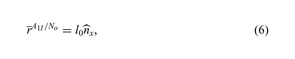

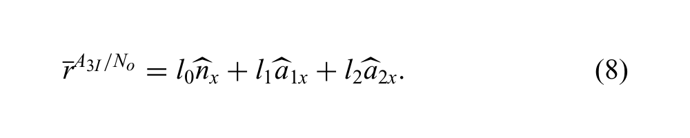
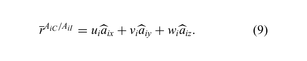
Contact points AiC are located on each body Ai, defined from the inboard joint location AiI by
The velocities of these points can be calculated using equations (6.1) and (7.1) from Mitiguy (2009), where
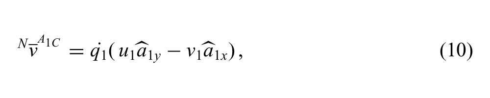
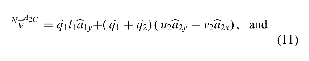
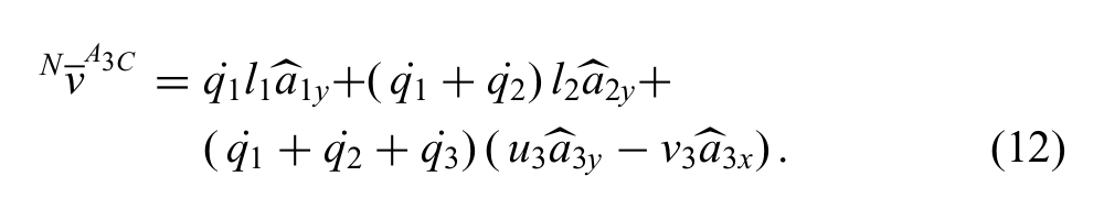
A local reference frame Ci, consisting of the right-hand orthogonal set of unit vectors
4.2. Transmission matrix
The ARM-H hand features a tendon drive with constant joint transmission ratios determined by the radius of the pulleys at each joint. The length of the tendon can be defined by the sum of constant and variable-length segments as the tendon routes through the finger. For a single joint where a tendon is always in contact with a pulley regardless of joint angle, the length segment surrounding the joint can be expressed as
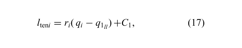
where C1 represents the length of constant-length segments surrounding the joint and
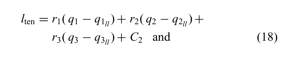
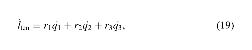
respectively, with C2 representing the length of all constant tendon segments in a finger, and
4.3. Dynamic and static equations
Torsional spring moments are applied to each joint along
The dynamics of a hand can then be described in matrix form by
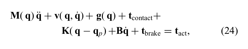
where
where
4.4. Brake contribution
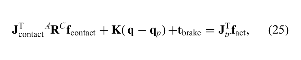
One example of the way equation (25) can be used is in the context of sizing the brakes to withstand particular loading conditions. Because space and packaging requirements in the finger dictate smaller brakes in distal joints, it is of some importance to dimension each brake so that it may be operated within the same range of loading conditions. Brake slip limits are determined by friction characteristics, the number of layers, and the part geometry; therefore with the holding requirements determined for a particular joint, one may tailor the brake design appropriately.
To frame the argument, we will consider a single finger pinching a 40 mm diameter sphere, with its center located at (0, 90, 0) mm in the
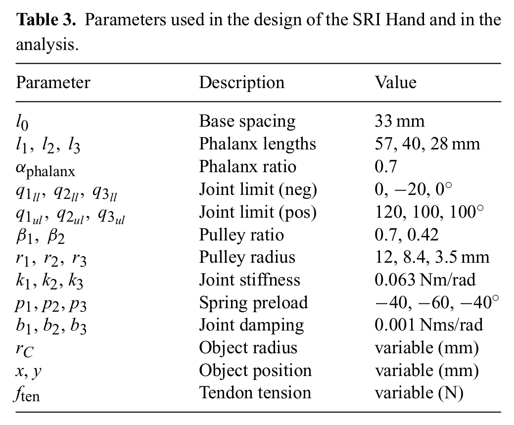
Parameters used in the design of the SRI Hand and in the analysis.
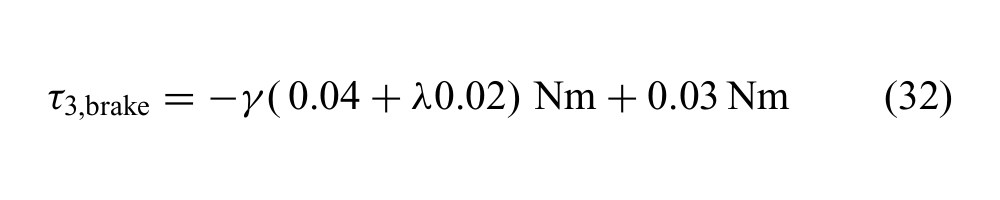
With the brakes engaged in this equilibrium configuration, any additional joint torques resulting from a change in contact force must be held by the brakes. By solving equation (25) for
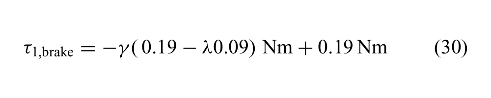
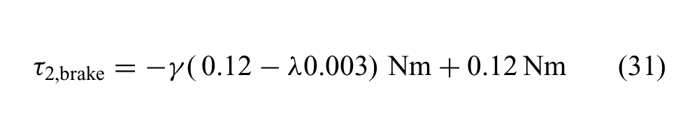
For γ = 1 and λ = 0, the loading configuration corresponds to that solved for in the unlocked state, and the joint torques are approximately zero. Increasing γ scales the normal force, and increasing λ scales the tangential forces due to friction. Separating the expression by these two terms allows one to analyze the frictionless and the friction cases separately, as the frictionless case would look at the change in γ as λ = 0. For example, at double the normal force capable of being held in an unlocked finger, or γ = 2, the joint brakes must hold up to |τ1,brake| = 0.20 Nm, |τ2,brake| = 0.11 Nm, and |τ3,brake| = 0.05 Nm, respectively.
When considering friction, one would look at the effect of scaling λ for a given γ by ± the expected coefficient of friction to understand its impact at the limits of the friction cone. Using the same configuration as above, and again given γ = 2, but this time with a coefficient of friction λ = ±0.5, the joint brakes must hold up to |τ1,brake| = 0.29 Nm, |τ2,brake| = 0.12 Nm, and |τ3,brake| = 0.07 Nm, respectively, higher than the frictionless case.
Equations of this type can be combined for multiple fingers and used to analyze grasps and regions in which objects can be acquired and held. However, for a compliant underactuated hand, consistency must be checked with every change in loading, as the finger will change its posture, making and breaking contacts at various locations, as discussed in Kragten and Herder (2010). Alternatively, one can use a fast numerical simulation package to keep track of contact formation and dissolution and to compute the contact forces. This method is discussed in subsequent sections.
4.5. Acquisition region calculation
For design purposes, analyses with and without friction are both useful. The frictionless analysis is useful as a starting point; it provides a “worst case” evaluation of the maximum pullout forces that the hand can resist, and it provides a way to evaluate many parametric designs rapidly, examining the space of possible locations from which objects of various sizes can be acquired. Conversely, analyses which consider friction provide a realistic estimate of pullout forces and trajectories, and permit one to evaluate the benefits of soft skin materials on the fingers. In this section we discuss a frictionless method to estimate the acquisition region of the hand, or the region where one might expect to be able to acquire an object. In the subsequent section, friction is considered when determining object pullout forces.
To determine the acquisition region, the quasistatic interaction between hand and object is formulated as a prescribed-path problem in Moby. The initial analysis is frictionless and takes place in a viscous environment, and while inertia terms are included in the simulation for the purposes of numerical stability, the system is allowed to settle to a quasistatic state. Because the fingers of the ARM-H hand are identical, simulations between a single finger and the object are performed to decrease simulation time. The kinematic, dynamic, and contact properties of the finger are defined in an XML file that is read by the dynamics engine. The object is a frictionless sphere fixed in space at (x0, y0, z0). The tendon tension is set to fini and slowly increased to ffinal in increments, and the finger is allowed to settle before each increase, allowing the system to approach quasistatic conditions. The simulation is re-run for a grid of valid object positions (xi, yi, zi) throughout the finger/object workspace, resulting in a set of vector plots, an example of which can be seen in Figure 11. The direction and magnitude of each vector represents the resultant force on the object for each simulated location.
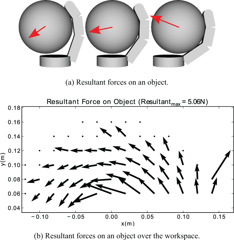
Resultant forces on a frictionless 45 mm radius sphere are captured in simulation by fixing the sphere at various positions and summing impulses over a discrete interval. Results are shown for a tendon tension of 25 N. The proximal finger joint is located at (0,0) in the plot. Dots are present at tested grid points which are not in contact with the object.
When Moby encounters a contact event, it generates a contact impulse which solves the quadratic program formulation for the system that prevents interpenetration between colliding bodies and satisfies all other equality and inequality constraints. An interface was written to accumulate contact impulses that occur for each timestep, and by summing them and averaging over the timestep, the average resultant force acting on the object’s center of mass is computed.
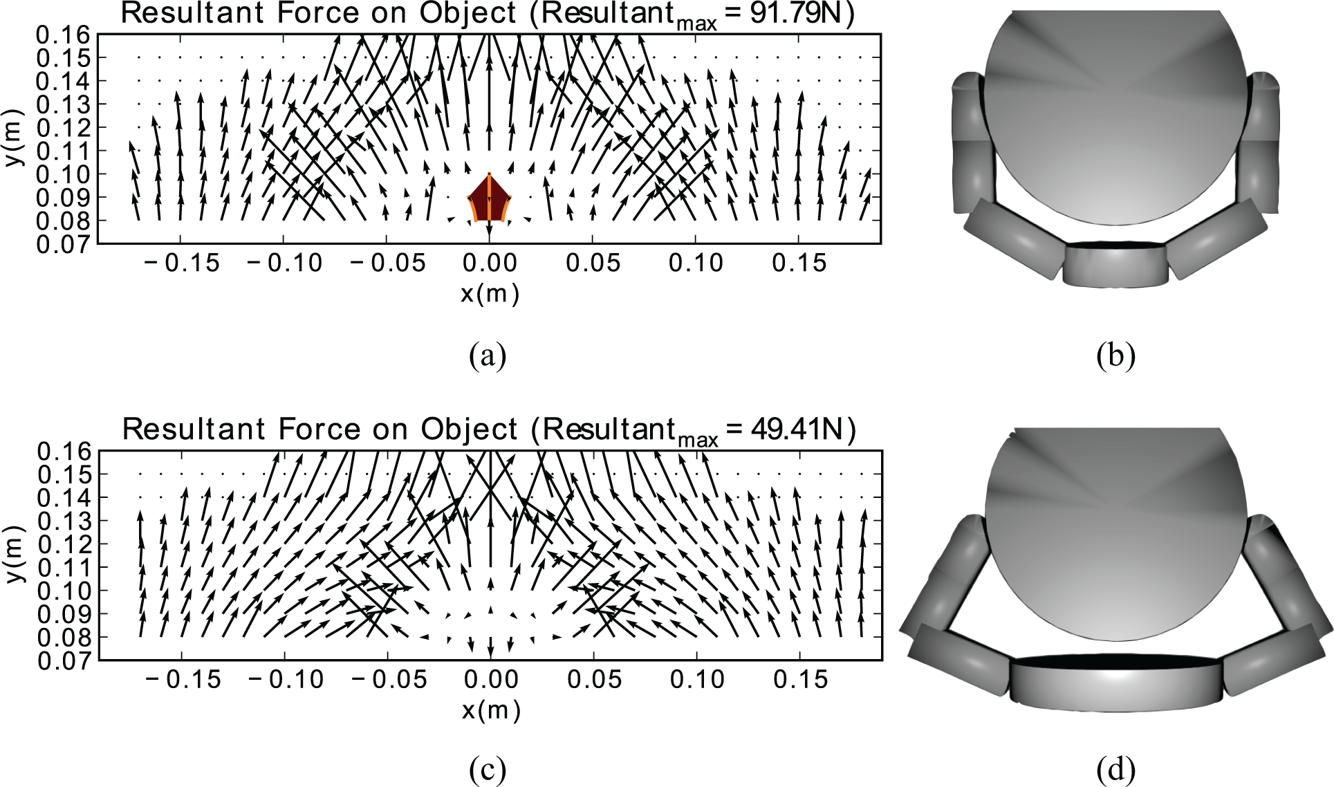
For a frictionless spherical object, the vector plots from multiple fingers can be superimposed by transforming and summing such a vector field according to the layout of each finger. While finger-to-finger contact is not considered, this assumption is valid for a wide range of finger topologies and object sizes. In addition, finger–finger interactions resulting from forces transmitted through the object are still accommodated. For example, Figure 12 shows the vector plot for two opposed fingers of the kind shown in Figure 11, with and without locked joints.
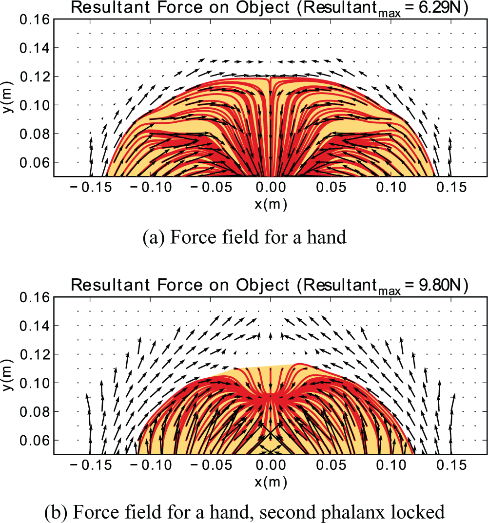
The forces for two opposed fingers on a 20 mm radius object are obtained by superposition. Arrows depict the forces at locations throughout the workspace. Red lines depict the quasistatic object trajectories. The shaded yellow area is the convex hull of points from which the object can be acquired. In the upper plot, the object is forced against the palm. In the lower plot, the middle joint of each finger is locked, producing a different equilibrium position away from the palm.
The method described above is one of many ways to obtain whole-hand force information, under the assumption that all fingers are identical. In the presence of more complicated kinematics, anticipated finger-to-finger contact, non-spherical objects, or actuation schemes that couple multiple fingers, it may be necessary to simulate the entire hand. The procedure described above can still be used to generate such a field, but the speed improvement associated with simulating the smallest atomic mechanical structure is lost.
With the force information generated, the region of object acquisition can subsequently be obtained by integrating the motion of the object from various starting points. A first-order differential equation is evaluated for each starting point as

4.6. Pullout calculation
In a second prescribed-force test, the kinematics of the entire hand are defined, and an object is placed at a starting location (x0, y0, z0). In this test, the tendon tension in each finger is fixed, and the object is allowed to move, either towards some static equilibrium, or completely out of the grasp. A disturbance force is applied to the object and gradually increased, allowing the system to come to rest after each step. The trajectory of the object is tracked until it is pulled from the grasp. Because this process uses the dynamic engine, contact or joint friction may be specified.
For the case of a frictionless pullout, the maximum force can also be determined directly from the static force vector field of Section 4.5. First, the object is placed inside an area of acquisition and its trajectory to some equilibrium position in the hand’s workspace is calculated. A small external force is then added in a prescribed direction, and the static equilibrium position is re-calculated. This process is repeated, and at each step the magnitude of the external force is increased by a small amount. When an equilibrium no longer exists, the object will leave the workspace, at which point the process can stop.
5. Hand design: Parametric studies
The object acquisition and pullout analyses described in the previous section were used to explore the effects of variations in finger spacings, link lengths, pulley radii and joint stiffnesses on the ability of the hand to meet the DARPA ARM-H requirements. Two representative examples are given here to illustrate some of the main effects.
5.1. Study I: Pulley radii
The relative diameters of pulleys at the proximal, middle and distal joints have a profound effect on the forces applied for contacts at each phalange. In general, a challenge with underactuated hands is to obtain sufficient pull-in forces for large objects. Acquisition simulations were run for a variety of pulley radii, with an object of radius 70 mm located near the palm. For each simulation, the tendon force and travel were set constant, with pulley radii set at each joint such that the overall tendon travel, st, was kept constant:
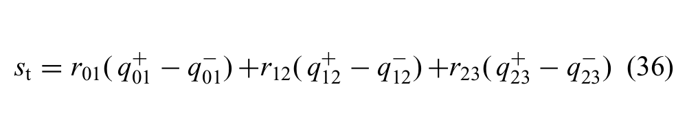
where rij is pulley radius at the joint between links i and j, and
The resultant forces on large objects are relatively small. As seen in Figure 13, the selected design, with r12/r01 = 0.7 and r23/r12 = 0.42, fares better than designs which either have too little tip force (upper example) or unproductive contact forces at the proximal phalanges (lower example).
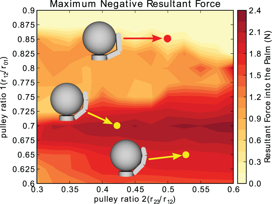
The effect of transmission ratio on the component of resultant force into the palm. Three designs are plotted to show differences in static configuration over the design space. These configurations, and the forces they impart on the object, can be optimized given finger kinematics. This example is for a sphere of radius 70 mm with fact = 50 N.
5.2. Study II: Base spacing
Figure 14 illustrates the effect of changing the base spacing for two fingers in an opposed grasp on a large object. The lower example is for a wide palm, corresponding to a finger spacing of 60 mm. It produces a higher force pulling large objects into the palm, but has no region of acquisition according to the analysis of Section 4.5. Hence the object must be firmly supported while the hand is pushed into it. The upper example, which uses the spacing of 33 mm from Table 3, has a 25% lower pull-in force but an almost 2 × 2 cm region of acquisition, even for large objects.
The upper example, corresponding to the actual base spacing of 33 mm, has a 25% lower maximum pull-in force than the 60 mm spacing. However, it has a modest region of acquisition whereas the lower example has none.
6. Experiments
6.1. Pullout trajectories
Pullout tests were conducted to compare hand behavior with the analysis of Section 4 and, specifically, to examine the effects made possible by locking joints with brakes.
The test setup consists of the SRI Hand mounted on a six-axis JR3 100-N Load cell (Figure 15). A webcam records images of the hand and object to measure displacement, tracking markers on the object and phalanges. It is calibrated using the image toolbox included in ROS. 10 Hand data, including joint angles, raw tactile sensor data, and tendon forces are also available through ROS. The hand has the ability to control motor positions and tendon forces through a stiffness parameter in the motor control loop. For the tests, the hand was set to control tendon forces.
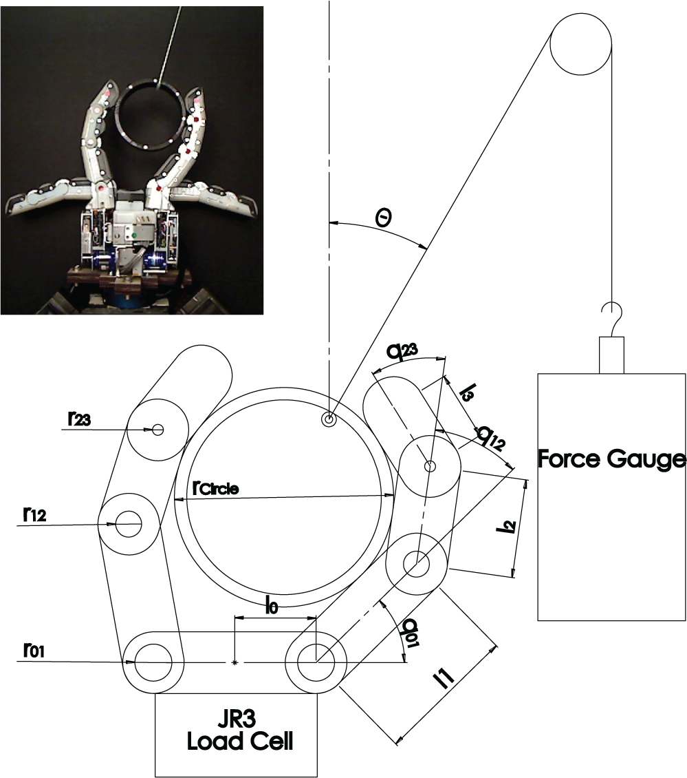
Pull test setup with hand mounded on a load cell and string attached to the roller to apply force through the object’s center of mass. A camera tracks markers on the object and fingers.
For pullout testing, hollow cylindrical objects are placed in the grasp, with the fingers exerting constant tendon forces. Because friction effects are path dependent, it is desirable to start with the object in approximately the same initial position for every repeated test. Therefore the object is shaken in the grasp, allowing it to settle at an equilibrium position. A cable is attached to a low friction roller inside the tube so that the force is directed through the center of mass. A force gauge provides a redundant measure of the external force.
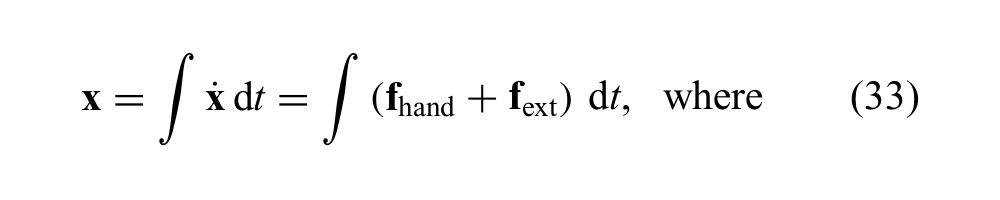
Figure 16 shows actual versus computed trajectories when pulling either straight out or at an angle of 30°. For the 0° pull test, the trajectory, with or without friction, should be along the y-axis, due to symmetry. The deviation of experimental trajectories (shown with circles) from the trajectories expected from simulation can be attributed in part to inequalities in joint torques and differences in local coefficients of friction. When pulling at 30° the effects of friction are more apparent. The frictionless simulation underestimates the lateral motion of the object. The quasistatic integrated path, computed as in Section 4.6, additionally shows the the effects of interpolating among a somewhat sparse field of vectors.
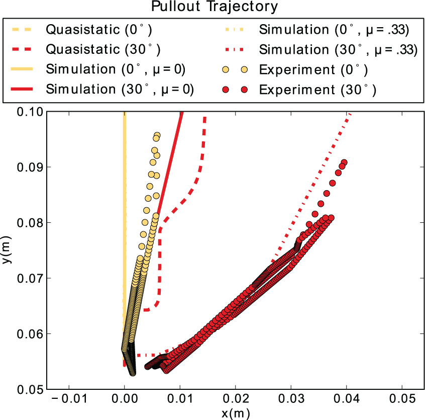
Object trajectories when pulling straight out (0°) and at 30° compared with simulated results with and without friction. Frictionless quasistatic paths (per equation (33)) are also shown for comparison.
6.2. Pull tests with locking
The benefits of locking to resist pullout can be seen in Figure 17, where the second phalanx was locked and a 44 mm cylinder was pulled out of a grasp. At all angles, the locked hand was better able to resist pullout for a moderate tendon force of 10 N. Error bars show standard deviations for several trials.
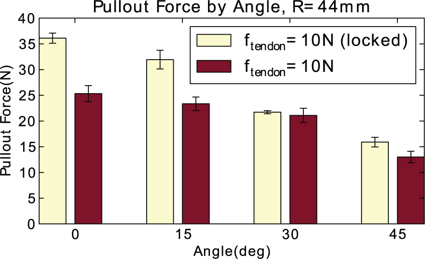
When comparing pullout forces with the second joint locked, it takes more force to pull an object out of a grasp at all pullout angles.
The use of joint locking to hold small objects is illustrated in Figure 18. In the left case, the object is pinched between fingertips and relies on friction. The middle case is a power pinch in which the object is partially enclosed by the fingertips. This grasp is obtained by locking the middle joints of the fingers in the desired configuration. In the right case, the fingers capture the object and the pullout force is considerably higher. This grasp can be obtained by transitioning from the power pinch, if the external force is not high, by unlocking the middle joints and allowing the fingers to pull the object toward the palm. (A demonstration of different grasps is included in Extension 1.)
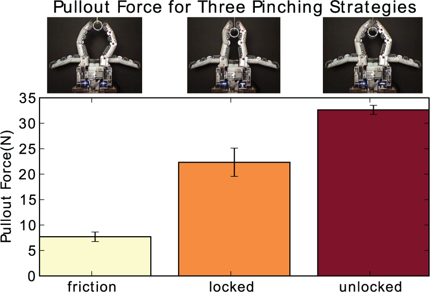
Three strategies are used to hold a small object. The left case is a fingertip pinch, which relies on friction. The middle case is a power pinch which uses locked middle joints so that the fingertips partially enclose the object. In the right case, which can be obtained by transitioning from the power pinch, the middle joints are unlocked. The fingers capture the object and will pull it into the palm if the external force is not too large.
7. Conclusions and future work
The SRI Hand aims to provide some of the versatility normally associated with fully actuated multifingered hands, but with considerably reduced cost and complexity. Notable features used to meet these goals are compact electrolaminate brakes at each joint and an integrated capacitive sensing system for tactile and joint angle sensing.
Simulations of the hand are used to determine parameters such as link lengths and transmission ratios with the goal of being able to acquire a wide range of object sizes and to resist high pullout forces for a given motor torque and tendon tension. In the first stage, the path-independent property of a frictionless simulation is useful for creating maps of resultant forces and regions in space from which an object can be acquired. Later simulations with friction provide more accurate estimates of pullout trajectories and forces. Future analysis will include enhancing the simulation tool to include explicit representations of internal joint friction and elasticity for more accurate predictions of forces and trajectories.
Many assumptions were made in the preceding analysis to improve simulation performance and enable higher fidelity results. For example, while the principle of superposition can be used in certain circumstances to improve simulation speed, it imposes several restrictions on the analysis which may not be desired for all designs. Another method to acquire the quasistatic force–position mapping without such requirements would be to simulate the entire hand at once. Such an approach, while somewhat slower to simulate, would allow designers to test kinematically coupled fingers and transmissions, implicitly testing the incidence of finger-to-finger contact at the same time. In addition, simulating an entire hand would enable the testing of a variety of objects other than spheres.
All the methods presented above can be performed just as easily in three dimensions as two. This gives designers the ability to investigate the effect of 3D finger placement, as well as the effect of finger surface shape. This requires the evaluation of a 3D space, increasing simulation time, but imposing no new restrictions on the method.
The evaluation of the region of acquisition by integrating interpolated data and finding a convex hull, while straightforward, requires thousands of integrations over a relatively sparse space. Furthermore, there is no guarantee that such a region is convex, so such a calculation threatens to be an overestimate, and in a 3D case, perhaps a gross overestimate. New methods must be developed which anticipate these issues and provide for more efficient computation from the provided sparse, gridded data.
A number of mechanical improvements are also anticipated. At present, the brakes are somewhat slow to achieve full locking and unlocking, relegating their use to discrete changes in hand configuration rather than continuous joint torque control. Even so, they allow the hand to achieve specialized grips, such as the power pinch, that would not otherwise be possible. As improvements in braking forces and response times are achieved, the compact and low-power nature of such devices will make them an attractive alternative to fully actuated systems in arms as well as fingers. Additionally, the possibility of using joint braking in a large number of joints makes such devices attractive for quasicontinuum systems such as snake robots.
Footnotes
Appendix: Index to Multimedia Extensions
The multimedia extension page is found at http://www.ijrr.org.
Funding
This work was supported by the DARPA Defense Sciences Office (DSO) and the Space and Naval Warfare System Center Pacific (SSC Pacific) under (contract no. N66001-10-C-4055). H. Stuart was supported by a National Science Foundation fellowship. Any opinions, findings and conclusions or recommendations expressed in this material are those of the author(s) and do not necessarily reflect the views of the agencies named above.
Notes
References
Supplementary Material
Please find the following supplemental material available below.
For Open Access articles published under a Creative Commons License, all supplemental material carries the same license as the article it is associated with.
For non-Open Access articles published, all supplemental material carries a non-exclusive license, and permission requests for re-use of supplemental material or any part of supplemental material shall be sent directly to the copyright owner as specified in the copyright notice associated with the article.