
Abstract
This paper presents the design, development, and verification of a miniature integrated jumping and gliding robot, the MultiMo-Bat, which is inspired by the locomotion strategy of vampire bats. This 115.6 g robot exhibits high jumping and gliding performance, reaching heights of over 3 m, to overcome obstacles in the environment. The MultiMo-Bat was developed by a novel integrated design strategy that combines jumping and gliding locomotion modes and minimizes the necessary actuation and structural components by sharing a significant portion of the components required for each mode; nearly 70% of the total robot mass is utilized by both modes. This results in overall low mass, low volume, and high co-operation between the modes which allows for the preservation of over 80% of the performance of the independent jumping locomotion mode when combined. This not only allows for two high-performance locomotion modes, but also for all of the necessary actuation components to be on board. Key considerations and components of the design are discussed in the context of the integrated design approach. A prototype of the system is constructed and experimentally tested in various configurations to elucidate the overall system and integration performance. Finally, metrics are developed to begin to quantify the level and performance of the integrated approach as well as allow it to be compared to other mechanical and biological systems. This type of jumping and gliding robot can be used to explore, inspect, and monitor unstructured environments for security and environment monitoring applications.
Keywords
1. Introduction
Operation in unstructured environments poses significant challenges to both biological and mechanical systems. This is due to the significant variation in the structural shape, size, and mechanical properties of features found within the locomotion domain, defined as the region containing all terrestrial, aquatic, and aerial environments. These challenges create regions in the environment where a particular locomotion strategy is able to operate. The size of these regions is a function of not only the locomotion strategy but, very importantly, the relative size of the robot compared to the obstacles it will encounter in the environment. Among the most challenging regions for locomotion are terrestrial environments where the robot is much smaller than the majority of the obstacles it encounters.
Mobility of small-scale robotic platforms within this region is an important challenge as it is a crucial step towards closing the gap between them and the biological world (Sitti et al., 2013). There exist two major methods for increasing a system’s ability to move through the locomotion domain: increasing the existing locomotion mode’s performance or the addition of an entirely new locomotion mode. This paper is focused on the latter, to improve the mobility of a small-scale robotic system through the utilization of two locomotion strategies. By sharing or integrating as many of the existing components and actuation mechanisms as possible with the new locomotion mode, the negative aspects of additional components can be minimized. Integration is of particular interest to mechanical systems because the current actuator technologies create significant limitations to their use; due to their size, weight, and versatility. Integration can therefore provide the best possibility of preserving the performance of individual locomotion modes, through an overall reduction of the number of necessary components, making the system smaller, lighter, and more robust. These modes include but are not limited to: walking/running, jumping, flying, swimming, and climbing.
For these small-scale systems, jumping has many advantages and therefore many robots in this size scale have been developed with this ability. Jumping locomotion strategies can reduce the cost of transport and therefore energy consumption of a robot operating in unstructured environments. With the addition of gliding, the kinetic and potential energy produced during the jumping mode can be utilized to increase the overall mobility of the robot. The smallest of these are centimeter-sized and around 1 g in weight; two of which are flea-inspired robots which use shape-memory alloys (SMAs) and another is a robot using nano-porous silicon and combustion to produce the jumping energy (Churaman et al., 2012; Noh et al., 2012). The next order of magnitude in jumping robots is where DC motors become widely available actuators. The smallest of these systems are the 7g jumper, which includes several different variants, and the Grillo robot (Scarfogliero et al., 2007; Kovac et al., 2008, 2009a, 2009b; Li et al., 2009). Several other jumping robots are under development within this size scale with abilities such as self-righting and rolling (Lambrecht et al., 2005; Zhao et al., 2009; Yamada et al., 2010; Zhao et al., 2010; Ho and Lee, 2012; Zhao et al., 2013). The next order of magnitude is robots on the kilogram scale, two of which use the combination of wheeled and jumping locomotion; the Rescue Robot which uses pneumatics to power its jump, and the Sand Flea (http://www.bostondynamics.com/robot_sandflea.html) which uses combustion to propel itself into the air as well as several other systems under development (Stoeter and Papanikolopoulos, 2005; Tsukagoshi et al., 2005; Tanaka and Hirose, 2008). However, there still exist performance challenges to these systems. Systems employing non-renewable strategies such as combustion or pneumatics can have very high energy densities, but cannot be easily recharged in the field therefore limiting their range. For electrically powered robots the challenge is to achieve sufficient energy density in the energy-storage devices to allow for additional components, payload, or even in some cases the inclusion of the actuators themselves on board. Many of these high-performance jumping systems show significant reductions in jumping performance when any additional components are added. There exist several robots which have both jumping and gliding locomotion strategies; however each requires certain assumptions for locomotion. The addition of wing membranes to the Glumper robot is not shown to produce gliding behavior, as the trajectory remains ballistic, resulting in only a reduction of the jumping performance (Armour et al., 2007). The 7 g jumper shows good jumping performance, however, with the addition of the gliding structure the jump height is reduced by almost 87%, requiring the robot to jump from an elevated platform to achieve gliding (Kovac et al., 2011). The Jump Glider shows both good jumping and gliding performance however, the energy storage is achieved by hand and held by a string which is burned through to initiate the jump (Desbiens et al., 2013). These challenges are the inspiration for this work, to show that integrated multi-modal locomotion design strategies can produce systems capable of more than one high-performance mode with all the actuation necessary for the modes on board. Only a few robots are capable of two locomotion modes and even fewer are well adapted for both. Also, of all the existing robots that do have multiple locomotion strategies, to the authors’ knowledge, none uses integration to combine high-performance locomotion modes.
The underlying idea of this paper, that integration of locomotion modes can be used to achieve increased mobility in robotic systems with minimal performance degradation, is discussed in the context of the design and development of a robotic system with two integrated locomotion modes: jumping and gliding. There exists some biological evidence that the integration of these modes is possible and an initial proof of concept was shown in Woodward and Sitti (2011), however these modes have very different and conflicting structural and actuation requirements. The challenge to the development of the jumping and gliding robot is the extraction of important concepts of the integrated multi-modal locomotion design approach taken by biological systems, and the application of these concepts to the robotic system with the utilization of high-performance actuation systems.
The paper is organized as follows: Section 2 introduces the biological inspiration for the jumping and gliding robot. Section 3 presents the design concept for the robot along with key performance features. Section 4 gives experimental demonstrations of the jumping and gliding robot. Section 5 develops metrics to quantify the integrated design characteristics. Section 6 discusses the overall outcome of the work, and Section 7 provides conclusions.
2. Biological inspiration for integrated jumping and gliding locomotion
The order Chiroptera (bats) provides a unique case study to examine the combination of terrestrial and aerial locomotion modes. The order includes over 1000 species of similar morphology which exhibit significant dissimilarities in terrestrial mobility, ranging from limited crawling to performance comparable to that of many small rodents, as seen in Desmodus Rotundus (common vampire bat). D. Rotundus is a sanguinivore, feeding exclusively on blood from terrestrial organisms. This ecology has driven the development several high-performance terrestrial locomotion modes, including jumping (Wimsatt, 1970; Altenbach, 1979; Schutt et al., 1997; Riskin et al., 2005, 2006). Originally thought to have fed on small animals, pursuit of moving prey necessitated the bat’s specialization in terrestrial locomotion; its jumping behavior was probably developed as an escape mechanism and/or as a means to transition to flight when highly loaded after feeding.
Our work is inspired by not only the mobility afforded by the jumping and flying modes but more importantly the particular method by which these two locomotion modes are combined in D. Rotundus. D. Rotundus shows a specialization for jumping, however a recent study shows that bat morphology in general may facilitate jumping. Several other bats with similar jumping strategies, albeit much lower performance, show performance dictated simply by body size and not ecological pressure (Gardiner and Nudds, 2011). This morphological predisposition toward jumping may be because the jumping and flying locomotion strategies can be highly integrated in bats as they are developed around the same primary musculoskeletal components. The main actuation of both modes is built around the largest muscle in the organism, the m. pectoralis profundus (posterior division). Both modes also share three main bones, comprising the main arm structure, which are the humerus, radius and ulna. This sharing of components, or integration, between locomotion modes can preserve a significant portion of the flight mode performance as the major components required for jumping already exist for flight. However, this alone does not guarantee the preservation of performance as the shared components themselves may be modified to accommodate the jumping mode.
An approximation of the cost, associated with modification to the major components, can be elucidated from a comprehensive study of the shoulder morphology of 29 species which includes D. Rotundus (Strickler, 1978). The two major muscles show scaling well within the range of the other species; implying no additional major muscle mass is required to power the terrestrial mode. The arm bones are slightly more robust and fusion of the radius and ulna has occurred increasing strength to accommodate the ground reaction forces. The bat’s jumping performance is therefore achieved through minor modifications to the shared flight structures, which tend to increase range of motion and independence of control. These changes result in low overall cost to the organism’s flight mode and indicate the success of this particular integration strategy. Applying the concept of integration to robotic systems is especially useful as the number of actuators that can be feasibly incorporated into a system and adequately powered is limited. The goal then is to abstract this particular integration strategy from the organism and apply it to the development of a high-performance jumping and gliding robot.
3. Design concept
The proposed integrated jumping and gliding robot inspired by vampire bats, called the MultiMo-Bat, is shown in Figure 1. The proposed design results in four phases of operation which can be seen in Figure 1: energy storage, jump, coast, and glide. The energy-storage phase is primarily responsible for storing the jumping energy in the main power springs. However, this process also produces a torque around the shoulder joint which reconfigures the legs for jumping. The jump phase can then be initiated through the release of the stored energy. As the robot leaves the ground, it enters the coast phase which continues until the apex is reached and it begins to fall. As the robot drops, drag on the underside of the airfoils reconfigures the wings and the glide phase begins. Locomotion is then achieved through repetition of this process. The design concept behind the MultiMo-Bat uses two key abstractions from the vampire bat’s locomotion strategy which tend to minimize the number of components and maximize their functionality. The primary abstraction is taken from the morphology of the arm structure and its function within the context of both modes; this dual functionality inspires the robot’s leg design. The second abstraction is associated with the connection between the wing and the shared leg structures. This connection results in inherent motion coupling between these two structures creating the possibility of reconfiguring the wing without additional actuation.
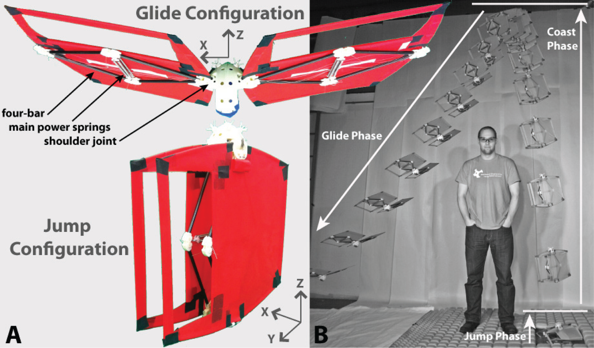
(A) Photos of the proposed jumping and gliding robot, the MultiMo-Bat, shown in the gliding (upper photo) and jumping (lower photo) configurations. (B) The MultiMo-Bat is shown overcoming an obstacle with three of the four phases of operation labeled. The energy-storage phase is not shown but would occur before the jumping phase.
In the vampire bat, the humerus and fused radius and ulna are the primary arm components used for both locomotion strategies. However, due to the inherently high degrees of freedom (DOFs), in the vampire bat’s musculoskeletal system, significant additional support and constraining components would be necessary to achieve the desired motion. Therefore, to mechanically reduce the DOFs of the leg structure, the two arm components were mirrored over the xz -plane (Figure 1). This creates the four-bar leg structure of the MultiMo-Bat which, being fixed at one joint, results in only two independent DOFs. The most important of which, the compression/extension of the diamond shape, allows for the motion necessary for both modes. This DOF serves to stretch the main power springs, transmit the jumping force to the ground, and tension the airfoil. The second is the rotation of the entire structure around the fixed joint. The second DOF can be used in the future for controlling the jump direction in the yz -plane. As the flight mode is currently unpowered, the direct sharing of actuation components will not be necessary for this prototype.
Because the major components of each mode are now shared, additional components necessary to achieve the individual modes may be attached to this shared structure. This creates inherent motion coupling between the shared major components and those attached. The goal then is to design this coupling such that it reduces any detrimental effects associated with the added structure. The sharing of structural components in the MultiMo-Bat generates inherent coupling between the leg configuration and the additional wing structure. This results in the ability to reduce the controlled DOFs necessary for the configuration change because changing the leg configuration changes the wing configuration. The wing membrane is connected directly to the shoulder joint and the foot, as seen in Figure 2; therefore, as the leg structure is compressed, storing the jumping energy, the wing membranes are inherently collapsed removing their effect on energy storage, as seen in Figure 3. As the legs extend, powering the jump, the wing membranes are extended as well; preparing them for the coming glide phase. However, the integration of the wings and legs also causes the wings, even when fully extended in the coast phase, to remain beside the body parallel to the flow which reduces their drag, preserving jumping performance. In fact, this configuration, acting like a tail, actually helps to stabilize the robot about the velocity vector, potentially improving performance.
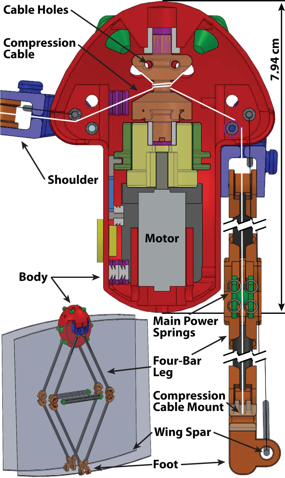
A CAD drawing of the half body of the robot showing the integration of the internal energy-storage mechanism and the SMA clutch. The full system is also shown for reference with the legs fully extended in the jumping configuration.
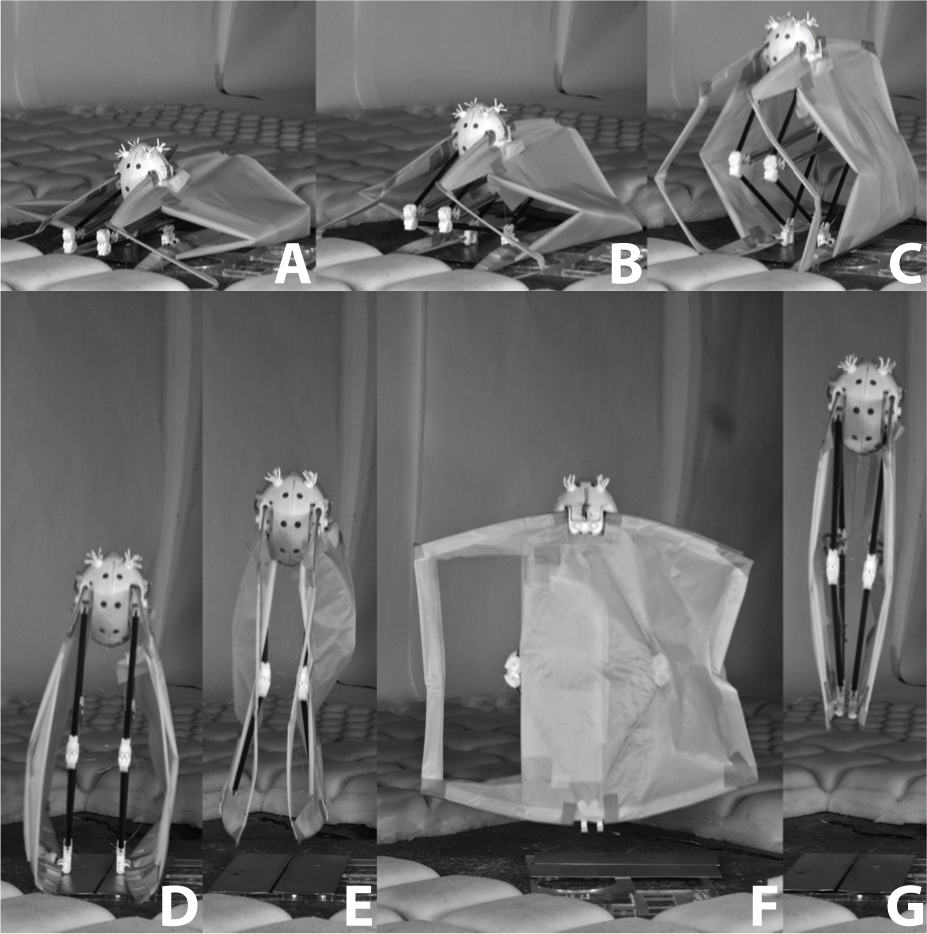
Video snapshots of the lift-off behavior of the MultiMo-Bat prototype which illustrates the wing membrane tensioning and the effects of the out-of-plane torques produced by the airfoils. (A) Initial jumping position with the membranes collapsed. (B) The four-bar legs begin to extend, powering the jump. (C) The membranes are reaching full extension. (D) The MultiMo-Bat just before it leaves the ground showing the airfoils inflated by the escaping air mass between them. (E–F) Front- and side-views of the robot at the point of maximum out-off-plane deformation. (G) The wings quickly stabilize at about a body length above the ground and remain beside the body until the robot nears the apex of the coast phase.
An exoskeleton can reduce the overall mass of the system while improving the durability, robustness, and protection of sensitive components. This structure is significant to the development of the MultiMo-Bat because occupying the extremities of the system creates significantly more surface area for the integration of attachment points for internal and external components. Engineered components, especially actuators and their transmissions, are typically much larger than their biological counterparts and therefore, the significant increase in attachment area facilitates design and development; as stated previously, the goal of integrated design is to reduce the number of components and increase component functionality. Exoskeletons, like their internal counterparts, are used to constrain components and produce fixed points for the actuators to pull against, with articulation only where necessary to facilitate locomotion. This concept is used in the development of the body structure for the jumping and gliding robot which consists of only two different components, the half body and the shoulder, symmetric about the yz -plane (Figure 1) resulting in a total of four components to create the entire structure, as seen in Figure 2. This results in very few connection points between components which creates a very strong structure as connections typically result in stress concentrations and therefore weak points in the system. Connection points also require additional features for fortification such that they are of equal strength to a solid single piece resulting in added mass and volume to the system. Protrusions on the side of the body provide mounting points for the shoulders and constrain the compression cable such that during compression a moment is generated on the shoulder which tends to rotate it back to the jumping configuration. Leg angle stops are designed into the shape of both the body and shoulder; the lower stop, at exactly −90°, is the desired position for jumping locomotion whereas a stop above 0°, for the gliding mode, helps to create lateral stability of the system in the air. All of these integrated features result in a total body mass of only 23 g.
The MultiMo-Bat is composed of just over 20 different components. Six, relatively basic, components are CNC machined (HAAS, Office Mill) to allow for the necessary materials; however, the remaining complex components, seen in white in Figure 1, are first 3D printed (Invision HR) and then replicated in a polyurethane, TC-892 (BJB Enterprises), through soft molding. This molding process allows for the creation of components which otherwise would be impossible to create, as individual pieces, as the part can be removed by deformation of the mold. This process facilitates the increase in component functionality while reducing robot cost; the full mass breakdown can be seen in Table 1. The major components are connected as follows, the four-bar legs attach to the shoulders which in turn attach to the protrusions on the body, as seen in Figure 2. The compression cable is routed from the internal energy-storage mechanism into the protrusions on the body and out through small slits. It is then passed through the small hole in the top of the shoulder and continues through the center of the springs and attaches at the foot of the robot. This routing of the compression cable constrains it to the plane of the legs which ensures the compression force produces no moment on the four-bar.
Prototype component masses.
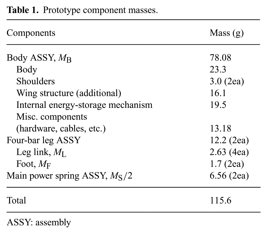
ASSY: assembly
The use of multiple locomotion modes inherently results in interactions between the modes which will affect the overall performance. These interactions can be broken up into three types of performance coupling: 1) inertial; 2) energy; and 3) structural. Inertial coupling will always exist, as changes in mass will affect both modes, but is inherently minimized through an integrated design approach. However, the second two may or may not exist as the additional mode may not change the energy state or the structural effects of the original modes. Integration is most importantly a method to preserve the performance of the individual locomotion modes when combined. Therefore, as with the development of a single-mode system, it is important to maximize the performance of both individual modes within the framework of the integrated design strategy to compensate for losses associated with the couplings. Certain interactions may not be detrimental and therefore can be used to improve performance. With an understanding of the coupling between modes, regions in which the performance of a single mode can be addressed individually may be determined. Three such regions important to the overall performance are discussed in the following subsections.
3.1. Jumping dynamic model
To understand the jumping dynamics of the robot, a single-DOF jumping model was derived in previous work (Woodward and Sitti, 2011), which includes all the components of the four-bar, springs, and body, where each one is modeled as a separate component contributing to the overall dynamics of the jumping locomotion mode. For the MultiMo-Bat, the absorbing springs are removed from the model, giving the dynamic equation as:
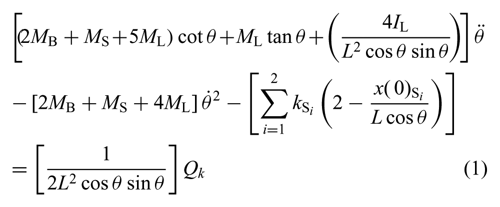
where θ is the leg angle that is measured from compression (0°) to extension (90°), and the masses of the body, springs, and legs are represented by MB, MS, and ML, respectively. The leg length and moment of inertia are represented by L and IL, respectively; full compression of the legs results in an angle, θ, of approximately 5° for maximum jumping energy. Finally, the main power springs are represented by their spring constants,
Solving the equation of motion numerically produces the jump profile shown in Figure 4, where the body velocity is related to
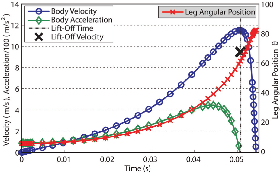
Dynamic simulation of the leg showing lift-off time and velocity in relation to body and leg states for the MultiMo-Bat. Leg position is shown on the right axis. Robot parameters MB = 78.08 g, MS = 13.12 g, MF = 1.7 g, ML = 2.63 g, L = 135.8 mm, IL = 40 g cm2,
3.2. Energy-storage mechanism
The most challenging components in small-scale robotic platforms are the actuation and energy systems because of their size, weight, power transmission, and performance characteristics. These issues tend to significantly reduce the overall robot performance. The MultiMo-Bat has an even more challenging configuration due to its jumping behavior, known as a catapult jump. It must not only have a high-power actuation system but also a high-energy storage system and rapid release mechanism. Jumping and gliding modes have high inertial coupling because increasing mass significantly affects the performance of both modes. Therefore, to improve performance, it is important for the components of the energy-storage mechanism to be lightweight and small in size. To increase mobility, the stored energy should be capable of being actively released at any point in the energy-storage phase. This provides not only the possibility for control over the amount of energy stored but also precise control over when it is released. The energy-storage mechanism of the MultiMo-Bat can be separated into and discussed as three distinct subsystems. First, the internal mechanism is responsible for supplying the input energy and force necessary to compress the legs. The second subsystem is the four-bar leg which provides the mounting and support for the main power springs. The last subsystem is the main power springs themselves, which are responsible for storing the jumping energy of the system.
The internal mechanism, as seen in Figure 5 and integrated into the system in Figure 2, has four main components: the base, reel, clutch, and actuator. The base attaches directly to a highly geared 298:1 DC motor (Solarbotics GM14a – Previous Edition) which can generate 0.317 Nm of torque at 6 V. The connections of the base, clutch, and reel are illustrated in the schematic section of Figure 5. Integrated into the base structure are slides which allow the clutch component to slide along the axis of the motor while constraining rotation, allowing the torque of the motor to be transferred to the clutch, as seen in Figure 5(b). The clutch component, in addition to the slides, also has a circular groove around the external surface in which the actuator arm rests. This groove allows the actuator to remain stationary while the rest of the mechanism rotates, facilitating electrical connection and actuator mounting. The actuator is composed of the arm, which connects it to the clutch, the nickel-titanium shape memory alloy (SMA) wire, which produces the motion, and pulleys used to extend the SMA length. The SMA (DynaAlloy, Flexinol) has a diameter of 0.2032 mm, a transition temperature of 70° C, and a maximum strain of 5% producing approximately 11.5 N of force to disengage the clutch. The arm is integrated into the overall design such that it is constrained to only a single translational DOF along the z -axis. The bottom of the arm has a polytetrafluoroethylene (PTFE or Teflon®) pulley which acts as the mounting point for the SMA. The remaining pulley mounts are integrated into the body of the robot. The pulleys are used to extend the length of the SMA to achieve the desired actuator stroke of 4 mm. Because of variation in the SMA characteristics and inconsistencies in the manufacturing process, a safely factor of around two is necessary to ensure the desired stroke is achieved. This results in a minimum SMA length of 160 mm which is approximately twice the length of the largest body dimension. To withstand the SMA transition temperature and maximize performance of the actuator, PTFE was chosen for its high operating temperature and low coefficient of friction. The final component is the reel, which is responsible for winding up the leg compression cable and increasing the force produced by the motor. The reel mounting can be seen in Figure 5. When engaged, the clutch slides fit into the slides of the reel linking the two components together; on release, the clutch moves down and the reel is decoupled and allowed to free spin releasing the stored energy. The reel has a radius of 2.15 mm which further increases the cable force to approximately 147 N, assuming 6 V operation, or 73 N per leg at the output of the internal energy-storage mechanism.
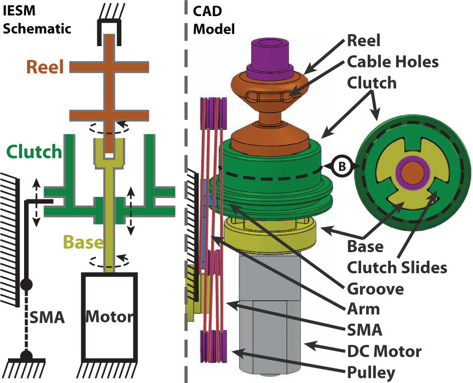
The internal energy-storage mechanism (IESM) is shown in schematic form to illustrate the joints and the mounting/fixed points of the mechanism. A CAD model of the mechanism is shown with the components labeled; which includes the SMA mounting pulleys used for extending the actuator’s resulting stroke length. Section B is a cross-section view which shows the clutch slides.
The second subsystem, the four-bar leg, is integral to both modes and is responsible, in the context of energy storage, for the mounting of the main power springs as well as the delivery of the jumping force to the ground. The four-bar leg also produces a beneficial variable mechanical advantage to the energy-storage system utilized for both increasing the amount of energy stored and holding that energy until the jump is initiated. The additional effective mechanical advantage is equal to approximately 2, resulting in a maximum approximate force of 147 N per leg to extend the main power springs. However, the energy can be held efficiently because the force profile approaches zero at full extension, requiring only the back driving friction of the mechanism to hold the legs (Woodward and Sitti, 2011).
The high-performance jumping mode of the MultiMo-Bat requires large energy storage springs which consequently contribute to a significant portion of the robot mass. It is therefore, necessary to understand if energy density can be maximized. Several spring materials were initially considered for the energy-storage medium including metals, elastomers, and composites. Elastomers were ruled out due to their low durability and robustness especially when exposed to the elements and under sustained strains. Composite springs may be interesting for further study, however the difficulty and expense of their fabrication ruled them out for this prototype, leaving helical extension springs as the most feasible option. Helical extension springs are typically thought of as a torsionally loaded rods which have a constant energy density as a function of rod diameter. However, two subtle differences between the torsional rod model and a helical spring create a situation where energy density is variable. Therefore, we would like to find a set of equations which maximizes energy density given the application variables, which are: extension length, maximum mounting length, desired energy, and the number of springs used to store the energy. The first difference is with the assumption that the bulk material properties remain constant. In fact as the wire diameter decreases, the yield strength, Sys, of the material increases, approaching the theoretical yield strength, because larger cross-sections have a higher probability of more significant defects. The second difference is associated with the fact that the rod is coiled and not straight which adds a direct shear component and creates a stress concentration on the inner most edge of the cross-section of the wire.
To achieve optimal spring design, two closed-form equations are derived in the Appendix, from the standard spring design equations, which relate the constraints of the system to the spring parameters. First, the mean coil diameter, D, is defined by two constraining features, the spring extension, y, and the maximum mounting length of the spring, Lm, along with a reduction factor, λ = 1 → 0, which reduces the free length of the spring to a percentage of the available mounting length. Therefore, equation (2) can effectively bracket the possible D and d values to those within the D(λ = 1 → 0) region. The region can be further reduced by increasing the lower bound of λ; Figure 6 shows lower bounds at λ = 0.5 and λ = 0.75.
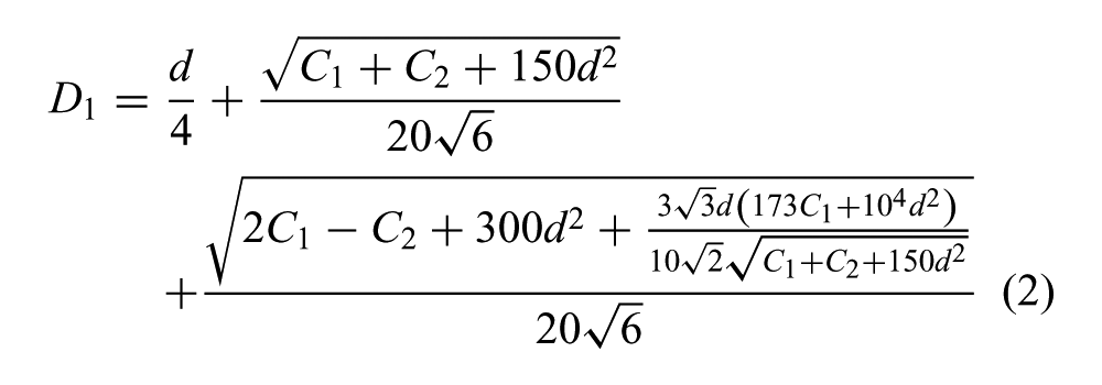
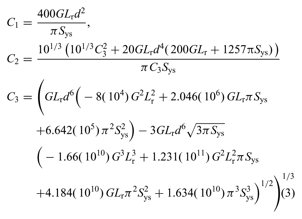
where Lr = y/(Lm λ) is the length ratio and G is the shear modulus. The mean coil diameter, D, is then related to the desired energy, E, and the number of spring used to store the energy, n, by:
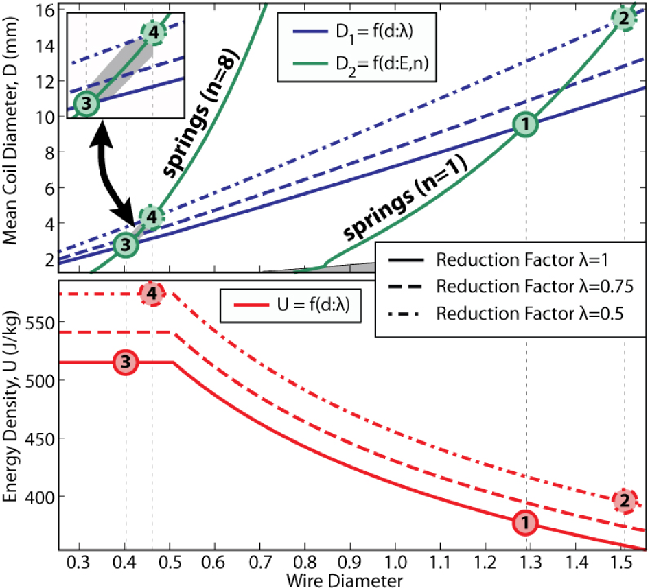
Shown is the relationship between the number of springs, n, the mean coil diameter, D, and the energy density, U, as a function of the wire diameter, d, the length ratio, Lr, and the energy, E for the MultiMo-Bat. Points 1 and 2 are using a single spring to store the energy however, while Point 1 fills 100% of the mounting length Point 2 fills only 50% but achieves an increase in energy density. The MultiMo-Bat uses eight springs to store the jumping energy which is labeled as Point 3, further increasing the energy density. Robot parameters: Lm = 71.1 mm, y = 147.6 mm, E = 6.35 J; material (A229) parameters (definitions in Appendix): R = 0.7, ξ = 1.05, Sys = 1.0119d−0.1833 GPa, ρ = 7.86 g/cm3, G = 79.3 GPa; defined range of d in equation (10) is 0.51–15.88 mm.
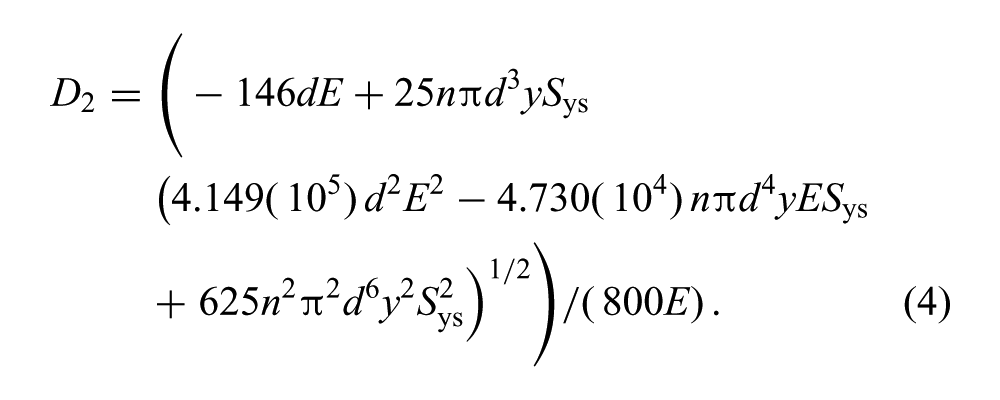
Bounding equation (4) by equation (2) gives the line of possible D and d values given the design parameters. If variation in the desired energy is tolerable, equation (4) can be used to create a region of possible values. The region between point 3 and 4, in Figure 6, shows the possible values when a ± 10% difference in energy is acceptable. This is useful when no standard spring sizes exist along the line of constant energy. Finally, the change in energy density, as it relates to the parameters of the system, can be calculated as:
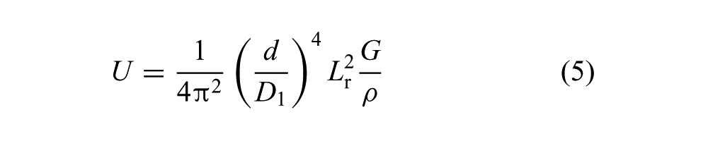
where ρ is the density of the spring material.
Equations (2), (4), and (5) are plotted together in Figure 6 which was created using the parameters of the MultiMo-Bat. The labeled points, 1–4, highlight two critical concepts for maximizing energy density, which are the number of springs used and the percentage of the maximum mounting length utilized. Point 1 is the natural starting point where the desired energy is stored with one spring which fills the entire mounting length. While still using a single spring, energy density can be improved by reducing the free length of the spring, however, the mean coil diameter grows rapidly and may not be tolerable. Point 2 shows the parameters when the free length is half the mounting length. To further improve the energy density, the number of springs used to store the energy can be increased. The MultiMo-Bat uses eight springs, labeled as Point 3, generating a significant increase in energy density. Point 3 yields a mean coil diameter D of 2.76 mm and a wire diameter d of 0.4 mm, which is a standard size. To compare this analytical solution to a previously used iterative strategy, the desired energy was set to 6.35 J, a value greater than the minimum required of 6 J, which is a known optimum standard size spring for this robot. In this case, both strategies produce the same spring parameters. The energy density, at Point 3, is 515 J/kg. For the MultiMo-Bat, the mounting configuration of the springs restricts the outer diameter of the coil to approximately the value at Point 3. Therefore, little length reduction is possible to further improve the energy density. The shear stress equation is only defined down to 0.51 mm for material A229 therefore, the allowable shear stress is held constant for wire diameters below this value which creates the artificial flattening in the curve. Extension of the ranges would be required to determine the true value but extrapolation might give some idea of the possible improvement.
Once a D and d have been selected, within the bracketed region which satisfies the system requirements, λ can be calculated by using equation (11) solved for F and substituted into the standard spring deflection equation. Solving this equation for λ yields:
The complete system is capable of storing a maximum of 6.35 J to power the jumping locomotion mode to heights of over 3 m. This analysis highlights the benefits of increasing the number of springs, meaning it favors smaller wire diameters which increase the material strength, and decreasing the percentage of the mounting length utilized, meaning it favors larger mean coil diameters to reduce stress non-uniformities in the cross-section. As compared to a more basic spring selection strategy, this guarantees that the designed spring achieves its maximum allowable energy density by accounting for the change in material properties and by ensuring that the spring reaches its maximum allowable deflection. The utilization of 8 springs by the MultiMo-Bat results in a 27% reduction in the spring mass as compared to the use of a single spring. More importantly, the reduction percentage is not constant and increasing the desired energy will increase the mass percentage reduction; for example, using the springs selected above to store twice the energy results in twice as many springs but, achieves a 36% reduction in the spring mass.
3.3. Wing design
The wings of bats are made of skin and are therefore similar to soft elastic materials. This property allows the wing membranes of bats to not only change shape but also surface-area-to-volume ratio, facilitating membrane collapse. Collapsing the membranes reduces their effect on the performance of the jumping mode. However, engineered elastomers have high mass and very low durability and robustness especially when exposed to the elements and under sustained strain. Therefore, various other materials were considered for the wing membranes. To achieve high durability and low mass, coated ripstop nylon (Goodwinds, 0.75 oz) was chosen for its high strength-to-weight ratio. This material has a ripstop weave to reduce the propagation of tears, can withstand ultraviolet exposure, and has a coating that reduces water absorption. This material however does not stretch, thus it can be deformed but it is not possible to use stored energy in the membrane to facilitate collapse. Utilizing this material therefore creates two significant challenges over an elastomer for the wing membranes of the robot.
The first challenge is due to the static behavior of the material, requiring that the membranes must be able to collapse in a way that does not interfere with the jumping locomotion mode. To achieve this, the wing membranes are mounted to the exterior of the leg structure and designed to be longer in the chord-wise direction than the leg structure when fully compressed (Figure 7). Based on the standard buckling theory of a beam, with two pin joints and no other constraints, Mode 1 is the lowest energy state and therefore is the stable configuration the membranes will adopt as the legs are compressed, however; it could be in either the internal or external direction. If it were to buckle inward it could potentially interfere with any one of the leg components resulting in reduced performance or structural failures. Ensuring the chord-wise length of the leg structure is always less than the membrane creates a restricting feature on the inside which ensures the stable Mode 1 buckling state is in the external direction, as can be seen in A–C of Figure 3.
The wing shape generated by the desired tension profile is shown along with the cut profile for construction. Superimposed on the graph is the manufactured wing to show the wing configuration and position of the center of mass. The opening in the wing is used for rapid testing of various center of mass (COM) positions, whereas the final wing should be constructed asymmetrically.
The next challenge is due to the integrated locomotion design concept. The goal is to add the gliding locomotion mode without significantly reducing the performance of the jumping mode. This requires that it does not affect the jumping energy delivered to the ground, does not produce significant additional drag during the coast phase of the jump, and requires minimal addition of mass. The vampire bat uses the major bones of the leg as attachment points for the membrane, and tension is controlled through the configuration of these components. This idea will be employed in the robot design to achieve similar results. The wing membrane is attached to both the shoulder joint and the foot of the robot, inherently collapsing the membrane when the leg is compressed. Extension of the leg creates tension on the membrane; however, as this is not controlled, tensioning is achieved through the utilization of a small amount of energy retained in the main power springs. The membranes are mounted to 1.53 mm diameter pultruded carbon fiber spars (Goodwinds). This creates a unique wing design in that it has no support in the span-wise direction allowing it to be highly deformable. However, without the leeway provided by the stretch associated with elastomers, the challenge is to produce the desired tension over the entire membrane.
To achieve the desired tension profile along the chord-wise axis, the carbon fiber spars can be used as distributed springs. Assuming the spar can be modeled as an Euler–Bernoulli beam, the deflections can be easily determined for several different types of loading conditions such as, concentrated tip loading, ramped loading, and equally distributed loading, as well as many other variations. This assumption also allows the use of the superposition principle which permits the simple addition of the effects of individual loading conditions to determine the total deflected shape. As the accuracy of the shape is very important, deflection values were obtained experimentally and used as a fitting parameter to adjust the elastic modulus of the material. Theoretically, this now allows for any tension profile, in the chord-wise direction, to be generated. The challenge comes in manufacturing the wing membranes with the required shape.
To facilitate manufacturing of the airfoil, it is advantageous to consider the magnitude of the second spatial derivative of the shape, the curvature, at the contact points of each loading condition. The greater the magnitude of this value, the more manufacturing error can be tolerated without reversing the loading condition on regions of the airfoil, such as going from a desired tension to slaking of the airfoil. As can be seen in Figure 8, the concentrated load at the tip creates the highest curvature over the region nearest the leading or trailing edge and should therefore be incorporated into the design to ensure edge tensioning. The ramped load with the peak at the tip causes the largest curvature variation over the region of contact and therefore, should be included to bias the load profile of the wing into tension and reduce the possibility of slacking. Finally, the distributed load should be included to generate a minimum desired tension. Also, to ensure that the least amount of energy possible is removed from the jumping mode, to achieve the desire tension profile, the tension at the base of the spar should not exceed the desired tension. Because of the rigid nature of the membrane material, any additional tension at the spar base will not contribute to the tension profile over the spars but will remove that energy from the jumping mode. As discussed in the jumping dynamic model section, the MultiMo-Bat lifts-off at 60 degrees therefore the energy to tension the MultiMo-Bat’s airfoils is stored above this leg angle resulting in no loss of jumping energy.
The second spatial derivative of the beam shape (curvature) provides an understanding of the amount of error which can be tolerated in the manufacturing process. Shown are the three loading conditions utilized for this system with normalized reaction forces to show the variation over the contact regions. The label (A) shows the position of this spar in Figure 7.
The design strategy for the wings is to first select a desired reaction force or leg deflection at the fixed point of the beam, then simply change the weights on particular loading conditions while maintaining the same reaction force. The current prototype uses all three loading conditions for the benefits discussed previously. They consist of a 0.7 N concentrated tip load, a 3.5 N/m ramped load, and a 1 N/m distributed load; the total reaction force is 1.09 N with the loads breaking down as follows: 0.7, 0.25, and 0.143 N, respectively. This results in a total leg extension change of approximately 2.3 mm; this small difference is due to both the high-performance jumping mode springs and the mechanical advantage profile generated by the four-bar leg. Then, from the beam shape, the complete wing shape can be generated and printed out at full scale for use as a manufacturing template, as seen in Figure 7.
The wing without the opening, shown in Figure 7, would result in parachuting behavior because the wing is symmetric about the center of mass (COM), whereas the desire is to glide in a particular direction. To achieve gliding, the airfoil should be asymmetric about the COM; the opening is to facilitate testing and will be discussed in the experimental gliding performance subsection. The goal then is to design a flying wing which is able to achieve horizontal velocity from a vertical jump. Furthermore, it is advantageous to design a wing which can passively achieve the gliding state to reduce the need for actuation and enhance the robustness of the mode. The key concept to consider is that the position of the center of pressure of an airfoil changes depending on the angle of attack (AoA) and velocity of the wing. Ideally for a flat plate airfoil, when the air flow is normal to it, the center of pressure is at the half-chord position, however, as the airfoil comes out of the stall – for a flat plate this is an AoA of around 15° – the center of pressure (COP) moves to the quarter-chord position. This is important because the wings are deployed parallel to the ground, therefore, as the robot begins to fall, they will initially see flow normal to the airfoil, however, for gliding it is necessary that the AoA is less than 90°. The passive transition to gliding can then be achieved by positioning the COM of the robot between the quarter- and half-chord positions as illustrated in Figure 9. Therefore, as the robot drops, the airfoils are initially rotated into the flow, by the nose-down pitching moment, as they come out of the stall, and the center of pressure moves forward, the resulting nose-up pitching moment slows the rotation and the system stabilizes around some glide trajectory.
The robot can passively re-orient through the positioning of the COM and the COP such that during the stalled state a pitch-down moment is generated and once the wings come out of the stall, the COP shifts generating a pitch-up moment. The boundaries of the COP are the half-chord position for stall, to the quarter-chord position for flying.
4. Prototype and experiments
To verify the performance and feasibility of the integrated design strategy, a prototype was constructed and tested (Figure 1). As previously stated, integrating locomotion modes has the potential to significantly reduce the negative effects associated with the additional modes, however, this may not entirely remove all effects. Therefore, it is necessary to quantify the effect that each mode has on the other to determine how well the integration was achieved. The primary mode of the MultiMo-Bat is the jumping mode with a highly integrated gliding mode resulting in a bias toward jumping performance. Therefore, jumping experiments were conducted to determine both the performance with and without the additional wing structure. Gliding experiments were then conducted to determine the best chord-wise position of the COM as well as the effect of passive vs. active wing deployment to the overall gliding performance.
4.1. Experimental jumping performance
The jumping performance of the MultiMo-Bat is a function of the energy stored in the main power springs, the release mechanism, and the configuration of the robot. Therefore, to test the integration performance of the robot, six robot configurations, seen in Table 2, were tested with the energy stored and the release mechanism held constant. Jumping experiments were conducted with robot configurations which included: with the wing structure, without the wing structure, and with a variety of wing deployment assist springs. The deployment assist springs are used to bias the robot configuration into the gliding state by generating a torque about the shoulder joint. The experiments with and without the wing structure were conducted to determine the major changes in performance associated with the addition of the gliding mode, whereas the experiments with varied wing deployment assist springs were conducted to determine the effect of the passive wing deployment strategy.
Prototype experimental jumping configurations.
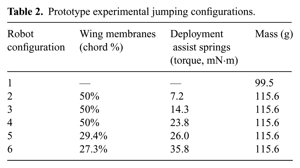
The overall jumping performance of each test was recorded using a high-speed camera (pco.dimax) at frame rates between 400 and 2000 fps depending on the desired motion resolution. The experiments were analyzed for both the maximum height achieved as well as the overall system behavior during the ascent phase of the jump. The maximum height achieved by the system provides an understanding of the overall power and drag of the particular system configuration, and the behavior during the ascent phase can show the coast phase stability of the system. For the jumping experiments, both energy storage and release were achieved by on-board mechanisms, however, the power and signal to operate the system were supplied off-board. Once the jump is triggered, the power tether falls away so as to not affect the jumping performance. For the Configuration 1 tests, which have the wing structure removed, the robot, seen in Figure 10 with the associated data in Figure 11, was able to achieve jumping heights of 3.63 ± 0.11 m. Configurations 2–6 of the MultiMo-Bat require the addition of 16.1 g, shown in Table 2, which is comprised of the wing membrane and support spars, to achieve the second locomotion strategy, gliding. However, with the addition of the second locomotion strategy the robot was still able to achieve a maximum jumping height of 3.15 ± 0.13 m; a reduction of just 13.2% for the full jumping and gliding robot.
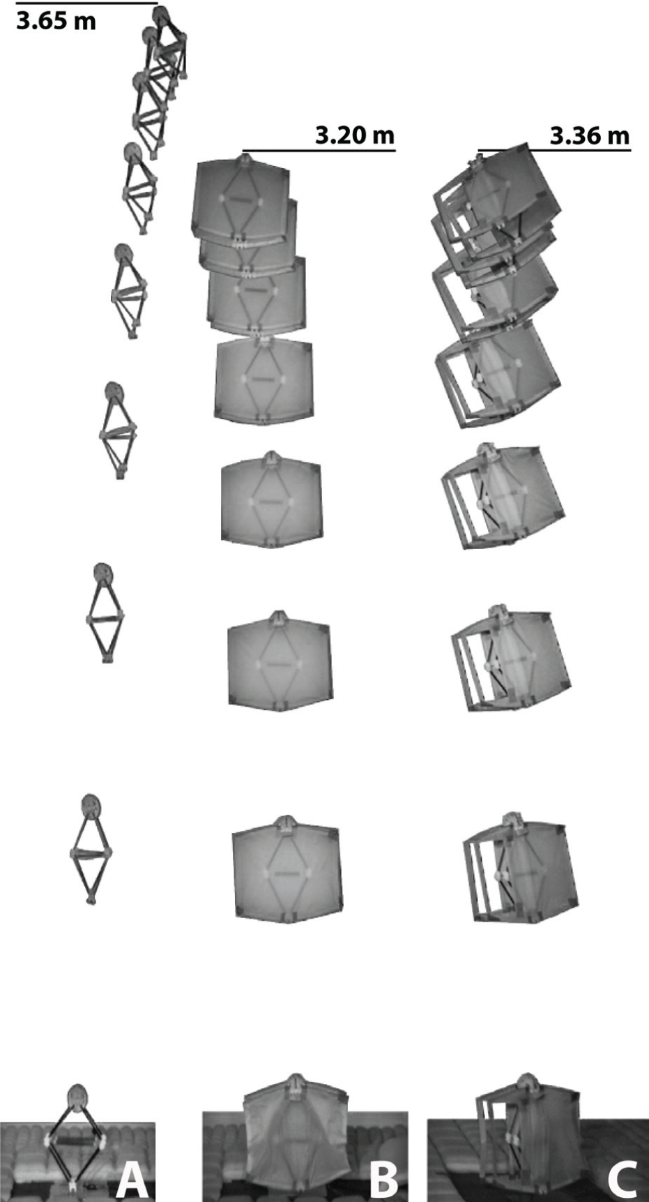
Shown are individual video snapshots of three jumping configurations which encompass the total variation in the jumping experiments. (A) Configuration 1, which has the wing structure removed. (B) Configuration 2, which has symmetric airfoils and no wing deployment assist springs. (C) Configuration 6, which has asymmetric airfoils and strong wing deployment assist springs. The interval between snapshots is 100 ms.
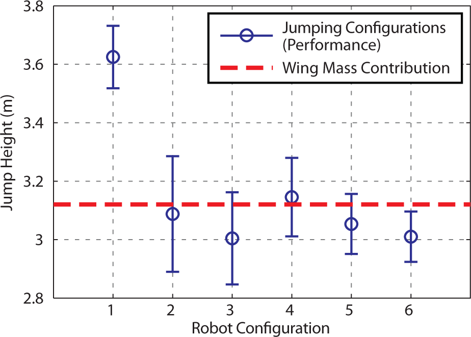
The jumping performance for the no-wing configuration (1) is shown along with the winged configurations (2–6) to show the change in performance associated with the addition of the gliding mode. See Table 2 for configuration details. The jumping and gliding robot performance is coupled in both mass and structure; however, the mass contribution is shown to illustrate how the integration strategy minimizes the mass contribution and has minimal structural contribution. The wing mass contribution line shows the loss in jumping performance associated with only the added mass of the additional wing structure, which shows other energy losses are minimal (minimum 10 samples tested per configuration).
The variability found in the experimental results has several potential causes, and should be considered for completeness. The major source of variation introduced into the results is the energy-storage mechanism for the jumping mode. Since the legs do not have a fixed stop, the extension length of the springs can be inconsistent between runs resulting in around ± 1.5% of possible variation in the energy stored. The cable used to compress the legs is wrapped around the reel and possible differences in the unraveling of this cable may result in changes to the performance. The coast phase behavior can also cause changes in performance; however, with the addition of the gliding locomotion mode the coast phase stability is improved. The large airfoils produce a restoring moment to any disturbances creating a more stable system and potentially reducing losses associated with undesirable body and leg motions, which can be seen in the jumping-only system. Finally, the jumping direction can have a small bias to either the forward or backward direction due to the cable attachment on the legs which affects the experimental results; for the jumping and gliding tests to follow, the bias was in the forward direction.
4.2. Experimental gliding performance
The gliding performance of the MultiMo-Bat is a function of several parameters which include the COM position in relation to the wing chord, the wing deployment type, the orientation at deployment, and the height. To analyze the effect of these parameters, three sets of experiments were conducted which include active wing deployment, passive wing deployment, and full robot tests. It is important to note that the active wing deployment tests only simulate active deployment by beginning the tests with the wings manually deployed. Determining the best position for the COM of the robot in relation to the wing chord was achieved through testing of various COM positions; the COM position is measured as a percentage of the wing chord length in front of the COM divided by the total chord length, as seen in Figure 7. To achieve the COM shifting behavior and facilitate testing of multiple positions, an opening was cut into a symmetric airfoil; for the final design the airfoil should be designed asymmetrically. The opening allows for the COM to be positioned between the half-chord position and just in front of the quarter-chord position which encompasses the extremes of the possible positions of the COP. It is important to understand that this is not steady-state gliding, as discussed previously, which is why the initial height will play a role in the gliding performance. Therefore, the maximum jumping height of the system was determined and the glide tests were conducted from a similar height to characterize the maximum gliding performance. The final parameter, orientation at deployment, will be discussed in the full system tests in the following section.
In the initial tests, the active and passive wing deployment experiments were conducted by dropping the robot from the approximate maximum jumping height (3.03 m) with the initial configuration of the wings set to the jumping configuration to simulate passive deployment and the gliding configuration to simulate active deployment. The COM position was varied from 20 to 40% of the chord, measured from the leading edge, over 6 steps with 4 points grouped around the maxima. This range ensured that tests were conducted with the COM in front of and behind the center of pressure – ideally for a flat plate at steady-state gliding the position should be 25%. As the behavior of the system is unsteady, the trajectory is much more of a stair step shape with a very steep initial drop, where the system re-orients to the flow and increases velocity, which flattens out and ends with the wings over rotating and re-entering a stalled state, as seen in Figure 13. To maximize the glide performance of this trajectory, the stall at the bottom of the trajectory should be achieved just above the ground to maximize the horizontal distance traveled as well as using the stall to remove energy from the system just before landing. The active deployment configuration will achieve lower velocities over the gliding range as the deployed airfoils create significant drag. However, the passive configuration initially drops with the wings beside the body, parallel to the flow. Thus upon opening they will experience higher initial velocity before stabilizing to the velocity of the active deployment configuration. This higher initial velocity and thus higher force requires a shorter moment arm to avoid premature over rotation and this is what we see in the experimental results in Figure 12. Illustrated in Figure 9 as the distance between the COM and flying COP, the pitch-up moment arm is larger for larger chord percentages and the maximum glide performance for the active deployment tests occurs at a higher chord percentage than the passive deployment tests. The glide performance is measured by the glide ratio, defined as the horizontal distance traveled divided by the maximum height of the robot. Experiments were conducted at 20% for the passive deployment configuration but were ceased before 10 runs due to potential damage to the robot as it dropped nearly straight into the ground. The best performance achieved, seen in Figure 12, was a glide ratio of 1.14 ± 0.06 at 29.4% of the chord, for the active configuration, and a glide ratio of 0.73 ± 0.02 at 27.3% of the chord, for the passive configuration. The jumping and gliding robot should therefore have performance within this range.
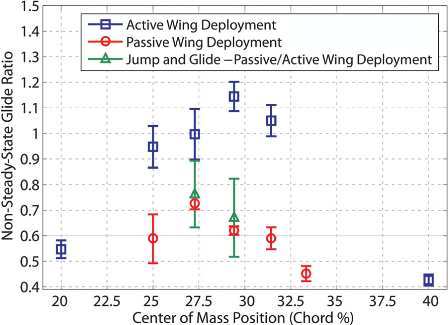
The initial wing state of the system for the active wing deployment tests is the gliding configuration, whereas the initial state for the passive wing deployment tests is the jumping configuration. These two states are the extremes of the possible initial configurations of the system at the top of the jump. The jumping and gliding system with passively deployed wings has performance bracketed by these two extremes, showing that the wings begin to deploy before the apex of the jump is reached (minimum 10 samples tested per configuration).
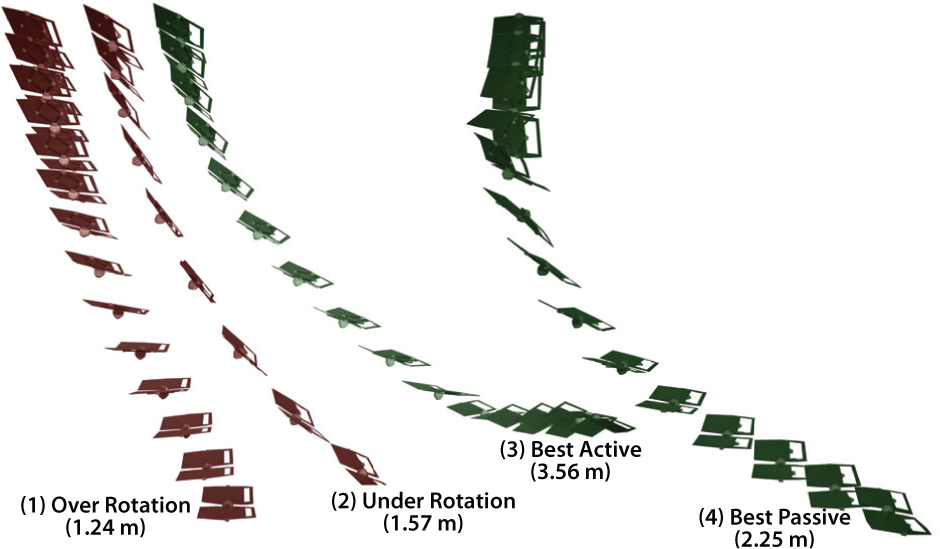
Video snapshots from individual runs of the wing deployment experiments, with the COM position at chord percentages from 20 to 40%. Runs (1) and (2) show the two extremes of the behavior; (1) shows over rotation (40.0%) and (2) shows under rotation (20.0%), both resulting in poor performance. Runs (3) and (4) show the behavior of the robot at the particular chord percentage which results in the best performance for both actively (29.4%) and passively (27.3%) deployed wings, respectively. The interval between snapshots is 100 ms.
4.3. Experimental robot performance
The MultiMo-Bat prototype has a combination of both passive and, to some degree, active wing deployment mechanisms. Small springs bias the wings into the jumping configuration. As the robot reaches the top of the jump the wings begin to deploy before the velocity vector of the robot switches directions. As the robot begins to fall and the velocity increases, the drag on the underside of the wings completes the deployment and the system begins the gliding phase of operation. To test the last parameter, the effect of the orientation of the robot on the wing deployment and gliding behavior, the complete system was used and underwent a complete locomotion cycle, shown in Figure 14. Starting from the ground, the system jumped up to the drop height, the wings were deployed, and the glide measured. By allowing the system to reach the drop height, through the jumping and coasting phases, the initial orientation of the robot, at wing deployment, would be varied by an amount equal to the variation of the system itself therefore ensuring validity of the experiments. Each run was captured using a high-speed camera, which allowed the jumping height of each run to be measured to ensure accuracy of the calculated glide ratio. The full system was tested at the COM positions which exhibited the best performance for the two gliding tests. The MultiMo-Bat achieved a jump height of 3.01 ± 0.09 m with a glide ratio of 0.76 ± 0.13 at a COM position of 27.3% of the chord, and a jump height of 3.05 ± 0.10 m with a glide ratio of 0.67 ± 0.15 at a COM position of 29.4% of the chord, shown in Figures 11 and 12.
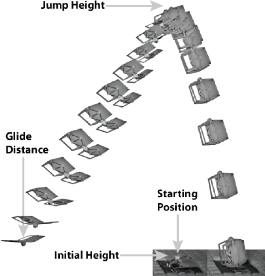
Video snapshots of a typical experimental run of the MultiMo-Bat with the measurement points labeled. The interval between snapshots is 100 ms.
As stated previously, the full system has springs that assist the wing deployment allowing them to open before the robot begins to fall. However, the full system experiments show close alignment to the passive wing deployment behavior, as seen in Figure 12. There is a slight increase in the glide ratio which is due to the tendency of the robot to jump slightly forward resulting in an increase in the effective glide ratio. Therefore, the deployment assist springs do not improve the gliding performance, however; without these springs any variation from vertical alignment of the robot at the top of the jump would cause the wings to not deploy and the robot to flip upside down and fall. This stability can be thought of in terms of a support polygon where the opposing force is the drag; if the gravity vector penetrates the wing membrane, the system is unstable. The bias these springs cause results in an increase in the support polygon size and therefore more tolerance to misalignment of the robot and a greater probability of successful wing deployment. Finally, there is one more consideration that should be taken into account. These airfoils stabilize the system about the velocity vector. Therefore any airflow in the environment will cause the robot to orient in the direction of the effective velocity of the robot plus the airflow. This effect can further complicate passive wing deployment. Therefore, to increase the deployment reliability, further designs should include an active wing deployment mechanism.
These experiments also show that the off-center mounting of the airfoils causes significant out-of-plane torque as the legs reach maximum extension, as seen in the bowing in Figure 3. The biologically inspired knee joints, discussed in Woodward and Sitti (2011), have been specifically designed to compensate for this effect. However, adding some compliance to the airfoil could also be beneficial in reducing this effect.
5. Integration and performance metrics
As introduced previously, these locomotion strategies are coupled in three distinct ways: inertial, energy, and structural. A quantitative method for identifying and comparing their contribution could significantly inform further robot design and development however, as of yet, none have been presented. As inertial coupling is the only unavoidable type, and it can be minimized by the integrated design approach, it would be beneficial to have a measure of the level of integration between the modes or the amount of sharing achieved by the system. Energy as well as structural coupling may or may not exist at all. Therefore, to understand the effects of each coupling type, it is necessary to evaluate the overall cost, incurred by the system, for the second locomotion mode. To begin to quantify these, two different metrics are presented in the following subsections. These metrics also provide an initial framework for comparing not only other similar systems but also their biological counterparts.
5.1. Mass integration metric
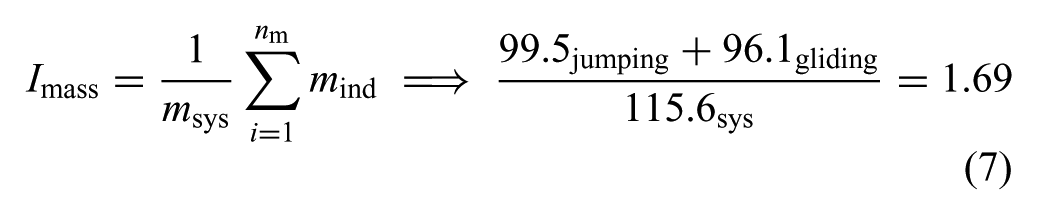
The mass integration metric, Imass, is a measure of the percentage of the total integrated robot mass required to combine the modes without any integration between them, and is given by:
where Imass has possible values of 1 to the number of modes, nm, which can be exhibited by a particular robot. One means no integration and nm means complete integration between modes. Also, mind is the mass associated with the components necessary for a specific independent mode and msys is the total integrated robot mass. As this metric is intended to provide insight into the amount of mass shared between modes, even though design decisions may be different for specific independent modes, the modes should not be redesigned to determine the specific mode masses. Further insight may be attained through assigning percentages to the masses of components used by each mode, however, as this is non-deterministic, it cannot be used for comparison. It is also important to note that this metric does not quantify the quality of the integration strategy.
The MultiMo-Bat requires an additional 16.1 g or just 14% of the system mass to achieve the second locomotion strategy, gliding. However, to evaluate the mass integration metric the two modes must be considered separately. The jumping locomotion mode does not require the wing structure to operate, therefore it utilizes 99.5 g of the total 115.6 g robot mass. The gliding mode does not require the use of the internal energy storage mechanism and therefore utilizes 96.1 g. This results in an integration measure of 1.69 at n = 2 meaning that 69% of the system mass is utilized by both modes, or another way to think about it is that the robot is 41% lighter than it would be without integration. This significant reduction in system mass results in the possibility of preserving a significant portion of the performance of the jumping mode; assuming the effects of the other two coupling types are minor as well.
5.2. Performance integration metric
The performance integration metric, Iperf, is a measure of the change in energy per unit mass, to a particular mode, due to the existence of the other locomotion strategies; it provides an overall understanding of the cost of the additional modes. This is achieved by measuring the energy state at the end of the locomotion cycle, of a particular locomotion strategy, both within the full system and with the unnecessary components removed. The energy state for the jumping locomotion mode is the sum of the kinetic and potential energies at the apex of the jump trajectory, assuming flat ground, and is calculated as:
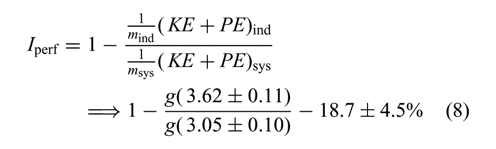
where (KE + PE)ind is the total energy of the independent mode and (KE + PE)sys is the total energy of the full system. It is then possible, with further analysis, to attain an understanding of the contribution of each coupling type which can facilitate further development.
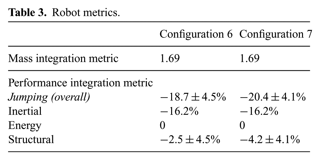
The performance integration metric for the jumping locomotion mode, of the MultiMo-Bat, is determined by comparing the overall jumping performance of Configuration 1, jumping mode only, to that of the MultiMo-Bat Configurations 5 and 6 (Table 2). This yields a performance integration value of −18.7 ±4.5% and −20.4 ±4.1% for Configurations 5 and 6, respectively. The loss of only one fifth of the performance is significant because of the difficulty in combining these two modes in a single system with on-board actuation. To determine the quantitative effect of each coupling parameter, the possible effects of each, as they relate to this specific system, must be considered. The gliding locomotion mode does not affect the energy coupling of the system and therefore, its contribution is zero, leaving just inertial and structural coupling. The contribution of the mass can be calculated as:
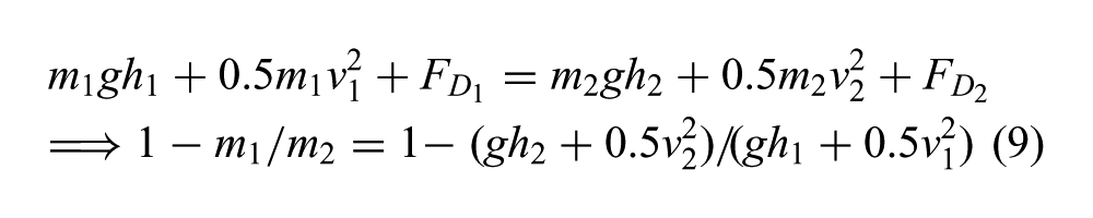
where mighi is the height potential energy and FDi is the non-conservative energies for both the full system, i = 1, and the separated jumping mode, i = 2. Setting the drag to be equal in both configurations,
Robot metrics.
6. Discussion
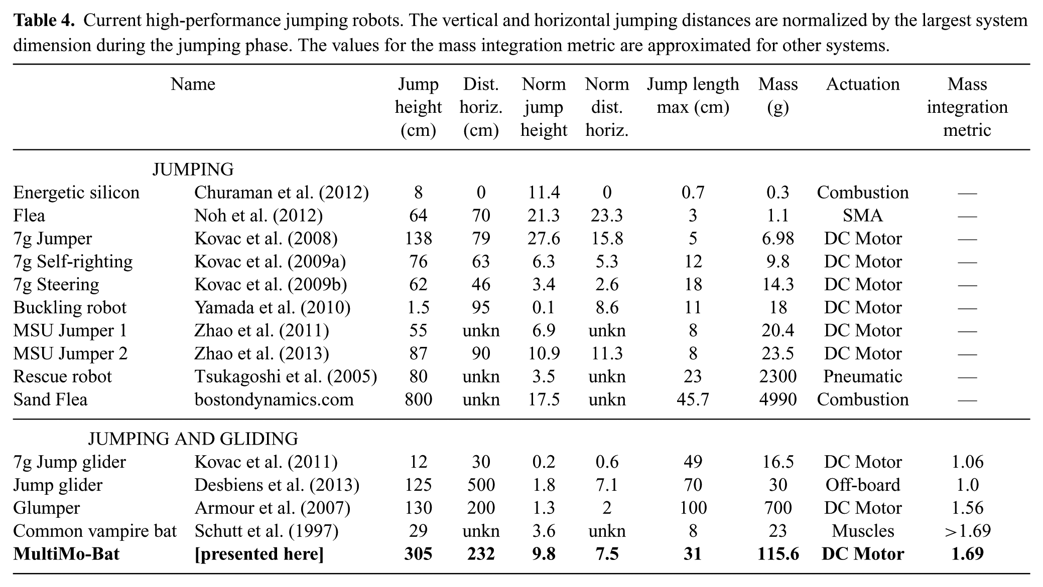
The MultiMo-Bat is able to preserve over 80% of the jumping mode performance which is quite significant because of the conflicting requirements of these two locomotion strategies. Jumping locomotion requires high energy per unit mass, high stiffness, and low drag to achieve high performance, while high-performance gliding requires large airfoils which could create very high drag during the jumping phase as well as significantly increase the mass of the system. With all of the conflicting requirements, the system lost only 20% of its jumping mode performance and 16% of that was due to the additional mass (16.1 g) of the gliding structure. This results in a minor 4% contribution from the structural coupling between the modes. This demonstrates that there exists a very high co-operation between modes and each is able to reconfigure itself to cause almost no negative structural effect on the other. The locomotion modes are also highly integrated, sharing nearly 70% of the total system mass, meaning that of the 83.1% of the system mass necessary for the gliding mode, only a small amount, 16.8%, of it must be added to the system. Consequently, the integration strategy abstracted from the vampire bat and employed in the design of the MultiMo-Bat is successful in creating a high-performance electrically power jumping and gliding robot. Shown in Table 4, the MultiMo-Bat has the second highest absolute jumping height even with the addition of the gliding mode. More importantly, normalizing the vertical and horizontal distances traveled by the largest dimension of the system, during the jumping phase, demonstrates that the performance of the integrated jumping mode is comparable to existing jumping systems and surpasses that of current jumping and gliding systems. This provides good evidence for proposing integration as a possible method for improving small-scale robot mobility.
Current high-performance jumping robots. The vertical and horizontal jumping distances are normalized by the largest system dimension during the jumping phase. The values for the mass integration metric are approximated for other systems.
To further improve the performance, an analysis of the coupling parameters can indicate where the biggest improvements can be achieved. In this case, the primary loss is due to the inertial coupling, which is the only unavoidable parameter, with the majority of that contained within the membranes themselves. Therefore, the largest improvement in performance would be achieved by the addition of lighter membranes.
7. Conclusion
An integrated strategy, abstracted from a biological system, for the combination of jumping and gliding locomotion modes has been presented which achieves high performance at a high level of integration. This is achieved through an understanding of the two key underlying concepts of integrated design strategies. The sharing of similar structures can preserve performance through decreasing the size and weight and increasing the structural cooperation. Maximization of individual mode performance is achieved, within the integrated framework, through the utilization of regions of the design which are uncoupled from the other locomotion modes. The MultiMo-Bat, with a mass of only 115.6 g, is shown to preserve over 80% of its independent jumping mode performance due to the integration strategy of the gliding mode. The MultiMo-Bat overcomes one of the most significant challenges to the maximization of individual mode performance, as it has all actuation components on board. These high-energy actuation components can exert forces of nearly 300 N, from a device which has a mass of only 19.5 g, to power the jumping locomotion mode to heights greater than 3 m. It also uses airfoils with no span-wise support and unique distributed springs to generate specific airfoil tension profiles to increase gliding performance while minimizing their effect on the jumping performance. The full system achieved a maximum glide ratio of almost 0.9 and the active wing deployment experiments achieved glide ratios of around 1.2. However, the airfoils have not been optimized. The current implementation of the airfoil design serves mostly as a proof of concept.
Future work would include optimized airfoils designed asymmetrically to boost the performance of the gliding locomotion mode. Folding, deformation, and active deployment strategies for the airfoils are under development to allow for larger wings, gliding control, and angled jumping. The current prototype also has the potential to increase its overall jumping power by 50% and therefore has significant performance to spare for additional payload and control electronics to create a fully untethered multi-modal locomotion platform. This small-scale, lightweight, inexpensive system has potential uses in environmental monitoring, exploration, search and rescue, surveillance, and deployed in large numbers swarm behaviors.The biological world is full of examples of integrated locomotion strategies however; the underlying concepts, of shared similar structures and inherent configuration changes, as well as the integration metrics are applicable to all integrated strategies.
Footnotes
Appendix: Derivation of the spring design equations
The relationship between the yield strength and the wire diameter has been empirically determined as:
where Q and b are fitting parameters associated with the material and d is the wire diameter used to calculate the ultimate tensile stress, Sut = Qdb (Norton, 2006). The ultimate shear stress is approximately equal to a constant percentage, R, of Sut and a safety factor, ξ. The rod is coiled and not straight which adds a direct shear component and creates a stress concentration on the inner most edge of the cross-section of the wire. The shear stress profile can be calculated as the sum of the torsional shear stress plus the direct shear stress. Assuming the wire has a circular cross-section, the maximum shear stress in the cross-section of the spring is:
where F is the force at full extension of the spring and D is mean coil diameter. To account for the curvature, Wahl’s Factor, KW, which also includes the direct shear factor, is typically substituted into the equation yielding the maximum stress in the coil; which is a function of the spring index C = D/d (Norton, 2006). To ensure maximum energy storage, the maximum shear stress in the coil is set equal to the yield stress of the material, τM = Sys. Then, equation (11) is solved for the applied force, F, and substituted it into the standard equation for calculating the spring constant of a helical extension spring. This combined equation can then be solved analytically for the mean coil diameter, D, as a function of the length ratio, Lr, and the wire diameter, d such that:
where the length ratio, Lr = y/(Lm λ), is a function of the spring extension, y, the maximum mounting length of the spring, Lm, and a reduction factor, λ = 1 → 0, which reduces the free length of the spring to a percentage of the available mounting length.
The final parameters for the design are the required energy, E, to be stored, and the number of springs, n, used to store it. Using equation (11) again, and substituting in F = 2E/(ny), the mean coil diameter, D, can be found as a function of E and n as
Acknowledgements
We would like to thank Meghan Downie for all her assistance in the experimental testing of the prototypes.
Funding
This research received no specific grant from any funding agency in the public, commercial, or not-for-profit sectors.