






Abstract
Fully autonomous applications of modern robotic systems are still constrained by limitations in sensory data processing, scene interpretation, and automated reasoning. However, their use as assistive devices for people with upper-limb disabilities has become possible with recent advances in “soft robotics”, that is, interaction control, physical human–robot interaction, and reflex planning. In this context, impedance and reflex-based control has generally been understood to be a promising approach to safe interaction robotics.
To create semi-autonomous assistive devices, we propose a decision-and-control architecture for hand–arm systems with “soft robotics” capabilities, which can then be used via human–machine interfaces (HMIs). We validated the functionality of our approach within the BrainGate2 clinical trial, in which an individual with tetraplegia used our architecture to control a robotic hand–arm system under neural control via a multi-electrode array implanted in the motor cortex. The neuroscience results of this research have previously been published by Hochberg et al.
In this paper we present our assistive decision-and-control architecture and demonstrate how the semi-autonomous assistive behavior can help the user. In our framework the robot is controlled through a multi-priority Cartesian impedance controller and its behavior is extended with collision detection and reflex reaction. Furthermore, virtual workspaces are added to ensure safety. On top of this we employ a decision-and-control architecture that uses sensory information available from the robotic system to evaluate the current state of task execution. Based on a set of available assistive skills, our architecture provides support in object interaction and manipulation and thereby enhances the usability of the robotic system for use with HMIs. The goal of our development is to provide an easy-to-use robotic system for people with physical disabilities and thereby enable them to perform simple tasks of daily living. In an exemplary real-world task, the participant was able to serve herself a beverage autonomously for the first time since her brainstem stroke, which she suffered approximately 14 years prior to this research.
Keywords
1. Motivation and problem statement
The application of robotic systems in rehabilitation, prosthetics, and in particular assistive technology has long been an area of research interest. Robotic systems could potentially be very useful in helping people with severe physical disabilities. For instance, for many people with tetraplegia, simple activities required in daily living such as drinking, opening a door, or pushing an elevator button, require the assistance of a caretaker, reducing the independence of the individual. An assistive robotic system (as illustrated in Figure 1) could enable people with tetraplegia to achieve greater independence and thereby increase quality of life.

An assistive torque-controlled robotic hand–arm system to support people with severe physical disabilities.
The number of assistive robots available on the market is limited. Examples of such assistive robotic devices are the Manus and the iARM by Exact Dynamics (Römer et al., 2004) and the JACO Arm by Kinova Robotics (Maheu et al., 2011). Such systems are generally controlled by a joystick, allowing the operator to move the arm in Cartesian space. A mechanical gripper, which can be opened and closed, is used to interact with objects. A joystick offers a rather intuitive interface, and thus provides some help to people with limited movement capabilities. However, the lack of apt haptic feedback both in the robot control loop and on the human–machine interface level makes it very tedious to perform simple tasks like safely picking up, holding, or releasing an object. While a joystick provides a reliable and transparent interface, the issue of missing feedback becomes more substantial when using interfaces that are less transparent or of varying quality. In these cases it would be beneficial to add locally autonomous capabilities to the robotic system in order to support the user in object interaction. An analogy to the concept of assisted teleoperation exemplifies the utility of this approach. As described by Bohren et al. (2013), teleoperation of a robotic system becomes very tedious when the control channel is low-dimensional. This problem is even more apparent when the only available feedback is given by visual information, which might, at least in the teleoperation scenario, additionally be affected by delays. To improve the usability of such a system, Bohren et al. added perception-based semi-autonomous capabilities to a teleoperated robotic system.
Different levels of autonomy can be conceived, from fully autonomous functionality of the robot, where the user only selects an action to be executed, down to fault detection and isolation, in which the robot would modify its behavior only in the case of erroneous input. The level of autonomy inherently has implications on the control capabilities (transparency) needed for the user interface. Thus, in a highly autonomous system, a low-dimensional input, such as a small number of discrete signals, would be sufficient to enable the user to select the required action from a pool of available robot functionalities. On the other hand, full autonomous functionality of robotic systems is still constrained by limitations in, for example, sensory data processing and scene interpretation and therefore not currently attainable, especially in unstructured domestic scenarios.
Furthermore, a fully autonomous device would limit the user to the functions provided by the system and possibly require external updates to adapt its capabilities to each user’s unique environment. Thus we envision a semi-autonomous approach to be most beneficial to people with limited movement capabilities. Ideally, the user should be able to freely and intuitively move the robotic system in space, but the system should support the user through partly autonomous behavior at task level. This supportive behavior would simplify the use of a robotic hand–arm system when controlled by a joystick as well. However, for locked-in or tetraplegic individuals a mechanical interface such as a joystick may not be suitable. Also in people with amyotrophic lateral sclerosis (ALS), spinal muscular atrophy (SMA), or other degenerative diseases, functional limb control capabilities can be extremely limited, and joysticks cannot be used. For these individuals, alternative ways to control technical systems have to be used where the benefits of semi-autonomous systems become even more evident.
To provide this semi-autonomous behavior to robotic systems, we developed a decision-and-control architecture that leverages the potential of so-called soft-robotics features in combination with invariant decisional skill automata. These enable the user to activate certain capabilities such as “grasping”, “placing”, or “drinking”, which can then be executed autonomously.
The generic gateway to our architecture is based on continuous desired Cartesian velocity input signals, and thus can be used in combination with any human–machine interface (HMI) that provides this control modality. In a pilot study, which serves as the template scenario, we used this architecture to enable a person with tetraplegia to autonomously pick up and drink from a bottle by controlling a robotic hand–arm system via the BrainGate2 Neural Interface System. The neural decoding component of this research has previously been published in Nature (Hochberg et al., 2012); here, we report on the robotics component of this work and how our decision-and-control architecture can help enable the execution of “real-world” related tasks such as the one presented here.
The paper is organized as follows: Section 2 provides a general overview of HMIs and their applicability for our approach. Section 3 explains in detail our decision-and-control architecture. Section 4 introduces the BrainGate2 Neural Interface System, which we used to demonstrate the functionality and feasibility of our approach. Section 5 explains the research sessions we conducted and Section 6 presents the achieved results. Section 7 gives a short introduction to our new approach towards an “electromyography (EMG)-based” interface, which will be used in combination with our framework in the future. Finally, Section 8 contains our conclusions.
2. HMIs
Manual interfaces such as a computer mouse, keyboard, or joystick serve as an effective control device for technical systems for able-bodied people. However, for people with physical disabilities, a variety of techniques have been developed to substitute for these manual interfaces. A common application in need of alternative interfaces is the steering of a wheelchair. For people who retain some head movement, for example, a special joystick can be mounted close to the chin and operated using neck movement. For people who are unable to operate a joystick-like device at all, head switches or sip-and-puff controls are commonly used as an alternative. A more sophisticated device is the Tongue Drive (Krishnamurthy and Ghovanloo, 2006), in which a patch of touch sensors is fixed on the palate and can be activated with the tip of the tongue. Another way of generating discrete control signals is by measuring the user’s muscular activity. In Felzer and Freisleben (2002) this is realized by recording eyebrow movements via piezo-based sensors. EMG can be used as an alternative sensing technology for this approach. All of these alternatives provide viable control capabilities for low-dimensional applications, such as wheelchair steering, but it is difficult to extract control signals with more degrees of freedom (DoF) or continuous signals from these low-dimensional input devices.
We envision continuous control signals to be advantageous for controlling assistive robotic devices. A widespread approach is the use of eye tracking systems (Jacob and Karn, 2003). These devices have proven to be effective in 2D control tasks, for example, moving a cursor on a computer screen. In the low-dimensional application of point and click on a computer screen, they can actually outperform standard HMIs like a computer mouse in terms of speed (Vertegaal, 2008). However, eye tracking does have limitations, for example if a person wants to look somewhere on a computer screen without necessarily making a selection there, when higher-dimensional control signals (≥ 3 DoF) are required (Duchowski et al., 2011), or when eye movements are unreliable or imprecise due to neurological disease or injury. Continuous control signals can also be acquired using surface EMG (sEMG). sEMG is a widely used approach for the control of hand prosthesis, either at the position level (Bitzer and van der Smagt, 2006; Smith et al., 2008), or in the domain of finger forces (Castellini and van der Smagt, 2009). In healthy subjects, recordings of muscle activations are also used to teleoperate robotic systems through position commands (Artemiadis and Kyriakopoulos, 2010; Vogel et al., 2011) or to improve the control of exoskeleton devices (Rosen et al., 2001). The latter approach can also be applied to robot-aided rehabilitation of hand (Mulas et al., 2005) or arm (Andreasen et al., 2005) function after stroke or other injury. With respect to assistive robotic systems, recent work shows that sEMG can also be used as a continuous velocity-based interface for people with severe muscular atrophy. In Vogel et al. (2013), two individuals with SMA were able to control a virtual robotic hand–arm system in a simulated version of our devised architecture.
All of the aforementioned interfaces require that the user has some residual movement or muscle activity. However, for people with no residual movement or muscular activity, acquisition of control signals can be realized by the use of brain–computer interfaces (BCIs).
In BCI research, there is a variety of approaches to measure neural activity and extract control signals from it. These methods can be distinguished by the spatial resolution of the neural recording, the achievable temporal resolution, the need for surgery, and the general applicability of the interface with respect to long-term use and mobility. To control an assistive robotic system via BCI, some neural recording techniques are not practical. Methods such as functional magnetic resonance imaging (fMRI) (Weiskopf et al., 2004) and magnetoencephalography (MEG) (Mellinger et al., 2007) require large-scale equipment and specially shielded environments, making them impractical for home or mobile use. Furthermore, fMRI and near-infrared spectroscopy (NIRS) (Ishikawa et al., 2007) provide a prohibitively low temporal and spatial resolution, with delays on the order of seconds (Hornyak, 2006) due to the properties of the underlying biological process, the hemodynamic response (Miezin et al., 2000; Cui et al., 2010). It is known from physiological experiments, especially in the context of tele-robotics, that a temporal delay of more than 250 ms significantly reduces the user’s ability to control a robotic system (Kim et al., 2005). Therefore, the BCI recording technique should detect and relay neural events within ≈ 0.1 s in order to keep the overall delay low and also allow time for the decoding process. There is a substantial difference in temporal as well as in spatial resolution between implanted and non-implanted technologies (Figure 2).

Overview of different brain–machine interfacing methods and their spatial and temporal resolution. Methods included: electroencephalography (EEG), magnetoencephalography (MEG), near-infrared spectroscopy (NIRS), functional magnetic resonance imaging (fMRI), electrocorticography (ECoG), microelectrode array (MEA) recordings and single microelectrode (ME) recordings. Reproduced with kind permission from IOP Publishing (Gerven et al., 2009).
The key features for different neural recording methods are listed in Table 1. If we take impractical recording techniques and those with poor temporal resolution out of consideration, we are left with the following methods:
Electroencephalography (EEG);
Electrocorticography (ECoG);
Microelectrode arrays (MEAs).
Brain–machine interfaces and their properties and practicability in controlling assistive robotic devices for domestic use.

The spatial resolution of EEG is limited relative to implanted interfaces. As a consequence, signals acquired via EEG are usually used for decoding discrete classes or sets of trajectories (Nijboer et al., 2008; Bradberry et al., 2010). Another common approach is in mapping motor imagery of single limbs (such as left hand vs right hand) to single DoF (McFarland et al., 2010). Online naturalistic continuous control has not been attained to date. In order to establish continuous control in Cartesian space, these discrete events can be transformed into graded control signals, but this approach leads to low bit rates. Such methods, still limited to 1D or 2D control in reported cases (Pascual et al., 2012), can be used to control lower-dimensional devices such as a wheelchair or for communication interfaces. However, at their current state of development, they seem to be unsuitable for control of assistive robotic hand–arm systems.
With current technology, higher bit rates can only be achieved with intracranial recording methods such as ECoG or a MEA. ECoG measures neural signals at the cortical surface, obtained by implanting a multi-electrode patch. Its common clinical application is the localization of brain areas involved in epileptic seizures. However, it has also been used as a signal source for BCIs. Most ECoG BCI studies to date distinguished execution or imagery of several different body parts in order to decode multi-dimensional signals online (Miller et al., 2007; Schalk et al., 2008). The more intuitive approach of mapping single limb intended movement to Cartesian control commands (continuous or discrete) has primarily only been applied offline, except for two recent publications: one that describes decoding of 1D single-limb movement direction online from ECoG signals (Milekovic et al., 2012), and one in which online multi-dimensional continuous decoding using single limb movement imagination is reported (Wang et al., 2013).
Higher-dimensional naturalistic BCI control in people has also been obtained with implanted MEAs (Hochberg et al., 2006), which have a much better signal-to-noise ratio than other BCI interface technologies. MEAs have been used to decode neural signals from individuals with tetraplegia to provide control of a computer cursor (Hochberg et al., 2006; Kim et al., 2007, 2008) or assistive robotic devices (Hochberg et al., 2006, 2012; Collinger et al., 2013), even after long-term implantation (Simeral et al., 2011; Hochberg et al., 2012; Jarosiewicz et al., 2013). To implement a naturalistic and intuitive interface capable of continuously controlling a robotic device, the spatial recording resolution needs to be sufficient to record neural activity representing desired motion of a single limb. Previous results with the above-mentioned recording techniques suggest that this control paradigm can more readily be achieved with the high spatial and temporal recording resolution provided by MEAs.
Though BCIs do not yet provide as precise control as direct interfaces such as a joystick, the potential availability of continuous control signals in combination with a more natural control representation make MEA-based BCI a promising interface for assistive systems when other HMIs cannot be used. To help compensate for the present limitations of BCI interfaces, it is necessary to add autonomous supportive behavior to the system to be controlled. The greater the bandwidth and signal stability/reliability of the BCI, the lower the autonomy of the assistive robotic system needs to be. While sensory feedback is expected to enhance the controllability, a bidirectional integration between the human body and an assistive robotic device is still very much a research endeavor. Although the possibility of adding sensory feedback via neural interfaces is being investigated (Thomson et al., 2013; Raspopovic et al., 2014), in current studies the interface remains unidirectional, with no feedback available except for visual observation of commanded actions (Arbib et al., 2008). Some interfacing technologies, like implanted neural interfaces, EEG, or surface EMG, provide shorter feedback delays, which improve control. However, the absence of somesthetic feedback may impede formation of a “tool” extension of the body scheme (Robles-De-La-Torre, 2006; Giummarra et al., 2008). Thus, using assistive systems is not yet as natural as might be possible. A semi-autonomous robotic system providing help in the complex task of object grasping and manipulation can possibly help to increase usability.
3. Technical approach
Accepting the limitations of current HMIs, we set out to devise an assistive robotic decision-and-control architecture to provide semi-autonomous behavior through combinations of various soft-robotics features, freely combinable skill libraries, assistive sensing capabilities, and appropriate, multimodal feedback channels to the user.
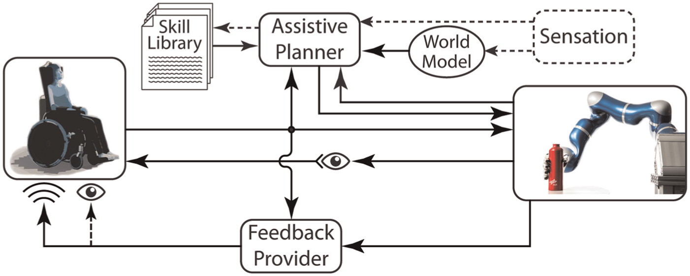
Schematic overview of our devised assistive decision-and-control architecture. The user controls the robotic system via HMI, while observing the robot’s movement. The Assistive Planner can modulate the robot’s behavior according to the skills available from the Skill Library. A World Model and external Sensation provide additional information for skill execution. To increase transparency of the system, the Feedback Provider supplies the user with auditory and visual feedback about the robot’s state. Note that components drawn with solid lines indicate the current state of implementation, while dashed components are envisioned features for future development.
3.1. Robot system and control
In our work we use the DLR light-weight robot arm LWR-III (Albu-Schäffer et al., 2007a) and the DLR five-finger hand (Liu et al., 2008) as a robotic platform. The LWR-III is a seven-DoF anthropomorphic robotic arm that weighs 14 kg. The integrated joint torque sensors can be used to realize direct torque control which is, for example, a prerequisite to implement true torque-based Cartesian impedance control (Albu-Schäffer et al., 2007a,b). Such a control approach is known to provide stable behavior when the system is in contact situations, but can also be used in situations where the commanding signal is of varying quality, which we exploit in our architecture. Additionally, other soft-robotics features including collision detection and reflex reaction (Haddadin et al., 2008) or virtual workspace limitations (Haddadin et al., 2011) allow for safe human–robot interaction, which is absolutely necessary in assistive robotic scenarios.
In order to incorporate a virtual environment into the control scheme and enable reflex-like reactions to collisions and contacts, we need to generate virtual obstacle forces and be able to estimate the external torques acting along the robot structure. Generally, the rigid-body dynamics of an articulated robot 1 can be described by
where M(
The virtual environment consists of workspace boundary wrenches
In order to account for the workspace limits also on the desired position/velocity level, we define the desired position
where k ≥ 0 is a gain factor that adjusts the responsiveness of the robot with respect to the desired velocity
where
This shaping function prevents the desired position (equilibrium point) from moving into the wall, in other words, it maintains the balance between a repelling virtual wall and attracting impedance forces. Finally, enabling the robot to react to physical contact with the environment requires estimating the external torques
In this study, the LWR-III is combined with the DLR five-finger hand (Liu et al., 2008). This robotic hand has three DoF in each finger and, similar to the robot, uses torque sensing in each joint. Thus it can be operated in impedance control mode as well, which allows for stable grasping of a variety of objects, even with a limited control signal like a binary grasp trigger. The dynamics of a single finger (denoted by the subscript f) can be described analogously to an arm (equation (1)):
The control of the individual fingers is realized with a simple proportional-derivative (PD) position controller
cascaded with a PD joint torque controller
This leads to a spring-like behavior of the individual fingers, which can be used to grasp objects while detecting the validity of a grasp. Figure 4(a) shows the hand in which the torques
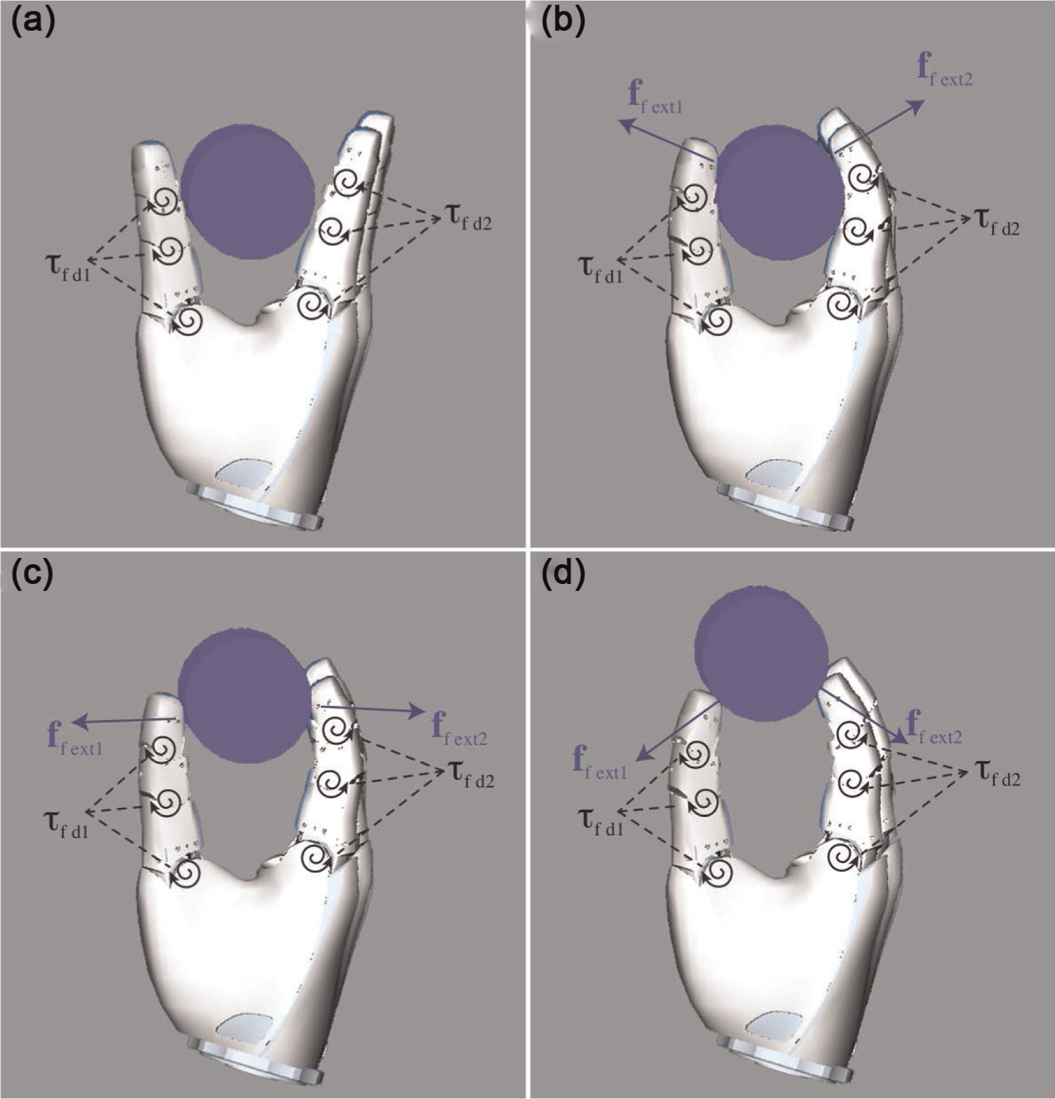
Different object contact situations: (a) depicts the hand when approaching an object and contact has not been established yet; (b) depicts a valid grasp situation, where the object is fully enclosed by the fingers. In (c) the object is not fully enclosed and the object might be able to tilt/slip, and (d) depicts a grasping situation in which the object is likely to be dropped, because the interaction forces push the object out of the hand.
The combination of
3.2. High-level control concept
To fully exploit the interaction capabilities provided by a torque-controlled robotic arm and hand, our assistive planner is employed by a high-level control layer in tight interrelation with Beasty (Haddadin et al., 2010; Parusel et al., 2011). A schematic overview of the control architecture is depicted in Figure 5. In the low-level control kernel, all algorithms run at a 1 kHz rate and execute the basic motion control, virtual environment, and collision detection with reaction patterns. The connection to the high-level control is realized via the real-time communication protocol Ardnet (Bäuml and Hirzinger, 2008). The control signals stemming from the HMI are communicated to the high-level control via user datagram protocol interface.

Simplified block diagram of the overall control architecture and signal flow. Depending on the state of the system, the high-level assistive planner communicates desired motion to the low-level control kernel. Behavior of the robotic arm and hand are handled in the two sub-states “Move” and “Skill Library”. In the “Move” substate, the user has free velocity-based control over the robotic system. Via the binary trigger signal, an assistive skill from the “Skill Library” is activated. In the robot control kernel a motion generator interpolates the motion commands to the control rate of 1 kHz and the Cartesian impedance controller calculates the desired torques that are commanded to the hardware. Safety algorithms like collision detection and reaction or the virtual environment are also handled within the robot control kernel.

Simplified visualization of an assistive planner for picking up and putting down an object controlled by one binary activation signal. Dependent on the state of the robot, different skills can be activated by the binary signal.

Simplified visualization of an assistive planner for a drinking task. Dependent on the state of the robot different skills can be activated by the binary trigger signal.
We have validated this approach in a real application, in which a participant with tetraplegia (“S3”) was able to control the assistive hand–arm system through the BrainGate2 Neural Interface System. 3 Via this interface, intended upper limb movement is decoded from spiking activity related to imagined arm and hand movement and used to directly control the Cartesian velocity of the robotic arm. The participant had free control of the robot’s velocity in 2D or 3D space within the predefined spatial limits of the robotic system. A simultaneously decoded binary activation signal related to grasp intention of the participant serves as a trigger for the assistive skills. The functionality of these skills is illustrated in Extension 3.
4. Neural interface system
The investigational BrainGate2 Neural Interface System (Hochberg et al., 2006, 2012) consists of a 96-channel MEA (see Figure 8) that was implanted in the motor arm/hand area contralateral to the dominant hand. The implanted array provided neural recordings with good spatial and temporal resolution for many years after implantation (Simeral et al., 2011) suggesting that the BrainGate2 Neural Interface System could provide a viable easy-to-use control interface. Raw neural signals were filtered using an analog bandpass filter (0.3–7500 Hz) and digitized at a rate of 30 kHz. Over the course of time in which the research sessions were conducted we used two different neural features (preprocessing methods) for decoding continuous velocity commands and a trigger state:
Neural spike rate;
Multiunit activity (MUA).

(a) Electrode array and the pedestal that provides the connection through the skull. (b) Close-up of the electrode array. Reproduced with kind permission from Nature Publishing Group (Hochberg et al., 2006).
In order to calculate neural spike rate, single units were identified from the raw neural signals by first detecting spikes exceeding a baseline threshold value on each single channel of the electrode array. Detected spikes were then classified into single units according to their waveform shapes. This waveform matching was realized via multiple thresholds, which were manually defined for each unit from visual inspection of the signals. Figure 9 shows an example of multiple neural waveforms recorded on a single channel and thresholds corresponding to a single neuronal unit. The sessions with participant S3 were conducted after five years of implantation and typically 8 to 15 single units were identified with mean spike rates ranging from 1 to 30 Hz.

Artificial example of spike sorting thresholds. The dark red thresholds separate the light red spikes from other spikes recorded on the same channel.
In contrast to the spike rate method, MUA preprocessing applied an initial baseline threshold criterion to the recorded signal on each channel of the MEA but did not further decompose the recorded activity into single units. Thus, MUA firing rate on each channel generally represents the activity of many cells in the close vicinity of the electrode. Typically, the signal is filtered with a highpass Butterworth filter with n = 2 and ωc = 1000 Hz.
Neural spike rate and MUA rate are simple and fast to calculate and both can be related to movement direction and velocity using a cosine model (Georgopoulos et al., 1982; Moran and Schwartz, 1999). For each neuronal channel acquired from the electrode array, a cosine model is parameterized to estimate direction-dependent velocity. Independent of the feature extraction method, a Kalman filter is used to join the output of the single models
As velocity is decoded from the neural signals, the state vector
The state transition matrix A, which linearly relates the system state
The training data set of size M used for this calculation is acquired in the beginning of each experimental session (see Section 5). The matrices A and H are kept constant within an experimental session. The process noise
5. Research sessions
To validate the functionality of our framework, a number of research sessions were conducted as part of the BrainGate2 clinical trial with one 58-year-old participant “S3”. This participant suffered a brainstem stroke more than 14 years prior to the study, leaving her tetraplegic and anarthric (unable to speak). She was implanted with a MEA in the dominant hand area of motor cortex in November 2005. The details of the research sessions can be found in Hochberg et al. (2012). Here, we summarize the aspects of the research session that are essential to understanding the context for the robotics contributions.
A typical experimental session started with the connection of the electrode array to the decoding system followed by a short system initialization routine. When single unit spike rate was used as a neural feature, the manual spike-sorting procedure was conducted. These steps were performed by a clinical technician. The participant was seated in front of the robot workspace as depicted in Figure 10 (on the right). The experimental part of the session was then conducted, consisting of the three following phases:
Open-loop decoder calibration;
Closed-loop decoder calibration;
Task evaluation.

Automated target placement and robotic system (left). Top view of the experimental setup with the participant sitting in front of the robot workspace (right). Reproduced with kind permission from Nature Publishing Group (Hochberg et al., 2012).
5.1. Open-loop decoder calibration
Open-loop decoder calibration served as an initialization procedure for the cosine tuning models and the Kalman filter used for velocity decoding, as well as the LDA classifier for the binary trigger signal (see Section 4). During the open-loop phase, the participant observed predefined motions of the robotic system and was asked to imagine making these movements with her own arm. The preprogrammed motion of the robot followed a so-called center-out-and-back pattern. In sessions in which 2D control was desired, the pattern consisted of four equidistant targets located in a plane above the table surface. The robot started at a fifth target, the so-called home target, which was located in the center of the other target locations. From here, the robot moved to one target randomly selected from the peripheral targets with a uniform probability distribution. After reaching the peripheral target, the robot moved back to the home target. Upon reaching the center position, the hand performed a grasp motion during which the participant was asked to imagine a firm grasp with her own hand.
In the case of a 3D session, one additional target was added to the open-loop calibration, which was located above the original center target, so that the targets span a 3D space. The overall training algorithm was as follows.
To promote accuracy in the imagined reaching movements and to promote consistent movement onset times, each upcoming trajectory of the robot was cued by a foam ball, which was placed at the target location using a motorized target placement system (see Figure 10). Additionally, an auditory cue was provided when the robot started to move. The duration of the open-loop calibration usually did not exceed five minutes. An initial parameterization of the decoding algorithm (Wu et al., 2006) was calculated from neural activity recorded during this open-loop task (see also Hochberg et al., 2012).
5.2. Closed-loop decoder calibration
A closed-loop calibration phase was used to refine the decoder parameterization that had been acquired in the open-loop phase (Jarosiewicz et al., 2013). In this phase the participant attempted to move the robotic hand sequentially to targets presented in the workspace. In the course of this research, the closed-loop training paradigm employed two different target configurations. In addition to the center–out configuration described above, a second configuration presented a home target located on the right side of the robot workspace with six targets on the circumference of a quarter sphere around the home target. In both configurations targets were positioned such that they were equidistant to their respective home target. Similar to the open-loop training, the robot started at the home target position and the participant was asked to move to one, randomly selected, peripheral target. After acquiring the target, or after a 20 s time limit, the robot automatically repositioned at the exact target location and the participant was asked to move it back to the home target.
To adjust for inaccuracies in the initial decoder estimates of intended movements, erroneous motion (motion perpendicular to the instantaneous target direction) was attenuated by calculating an error attenuated desired velocity
The parameter α ∈ [0, 1] was used to scale the amount of attenuation and was gradually increased from 0 to 1 during the closed-loop training. The parameterization of the decoder was then updated iteratively during the closed-loop training procedure. After approximately 30 minutes of this training, full Cartesian control over the semi-autonomous robotic system in combination with skill triggering was granted to the user.
5.3. Task evaluation
In the task evaluation phase a predefined standard assessment task was performed multiple times in order to calculate success rates and other measures of performance. During this phase, the parameterization of the decoder remained unchanged. These tasks had been performed with the robotic framework:
2D/3D positioning;
2D/3D reaching;
2D/3D reaching and grasping;
2D glass pick-and-place;
2D drinking.
6. Results
In this section, we present the results from experimental sessions in which S3 controlled the robotic hand–arm system in combination with our decision-and-control architecture integrated with the BrainGate2 Neural Interface System. Results from the more synthetic ball-grasping assessment task are discussed in more detail by Hochberg et al. (2012), who focus mainly on the neural control aspects of this research. Here, we give only a short presentation of that specific task for the sake of completeness. The benefits of our assistive decision-and-control architecture are more evident within the “real-world” tasks of pick-and-place or drinking.
6.1. 3D grasp task
To evaluate and quantify the general performance of the BrainGate2 Neural Interface System with respect to 3D robot control, we asked the participant to reach and grasp a target foam ball in 3D space. Figure 11 depicts the success rates for two experimental sessions with 32 and 48 trials, respectively, in which S3 performed this task. These sessions used MUA as the neural feature for decoding. In addition to detecting grasp state from the torque sensing in the fingers, we also determined when the fingers established contact with the target ball through visual inspection of video recordings. Though the participant was able to move the robotic arm to contact the target ball (“touched”) in 50% of the trials, she was only able to attain a full grasp in 20% of the trials. We expect this to be the result of the target ball being large compared to the maximum aperture of the hand (6 cm ball radius vs 8 cm aperture), making the task very hard. While this result shows that BrainGate-enabled 3D control of a robotic system is possible, the participant did not gain practical benefit from the assistive skills provided by our framework in this particular task. Of course, the soft-robotics features provide safety in any scenario. However, the actual assistive skills of our framework were used in this task only for evaluating the success of the task and did not improve or even affect the usability of the robotic system in this particular setting. Footage of the 3D grasp task can be found in Extension 4.

Results for 3D grasp task from two trial days (touched = target foam ball has been touched with the hand; grasped = target has been physically squeezed). Left: success rate; right: time to target for successful trials. Reproduced with kind permission from Nature Publishing Group (Hochberg et al., 2012).
6.2. 2D glass pick-and-place
In order to validate the supportive capabilities of the assistive planner in combination with true torque-based impedance control, we examined the performance of the system in a realistic pick-and-place scenario. Figure 12 depicts excerpts from a glass pick-and-place task participant S3 performed in one of the experimental sessions at an early stage of the study. Footage of this task is available in Extension 2. During this session, we used the spike-sorting technique described in Section 4 as a neural feature for the decoding. The colored circles (1–5) mark different targets to which the participant was instructed to command the robot during this session. The quadrangular gray-shaded area shows the desired workspace of the robot with respect to the robot’s tool center point (TCP). As the TCP was located in the middle of the robotic hand, it was still possible to move a portion of the hand above a target which was visually mainly outside the TCP workspace (as depicted at target 3). In this specific task, the hand of the robot originated at target 1 and the participant was instructed to move towards the randomly placed glass, grasp it, and bring it back to target 1. It is observed that after picking up the glass the participant moved with a short detour to the desired target but then redirected to target 2. Clearly, the virtual workspace boundaries supported the recovery of the task in this particular setup, because several targets were located at the border of the workspace, thereby artificially decreasing the DoF required for the task. Therefore, targets were not positioned on workspace boundaries after this initial pick-and-place test.

(Left) Photographs from a glass pick-and-place session: (a) moving to the glass, (b) grasp the glass, (c) move with glass, (d) put down. Right: reconstructed tool center point (TCP) motion from top view. Capital letters mark the locations of the corresponding photographs of panels (a)–(d) along the trajectory.
6.3. 2D drinking task
In order to explore how a set of available assistive skills can help in a more sophisticated “real-world” task of controlling a robotic system via a neural interface system to achieve activities of daily living, we extended the pick-and-place task to give the participant the capability to independently drink from a straw. The task was to pick up a bottle of coffee, move it to her mouth, drink from it through a straw, and finally place the bottle back on the table. The dimensions of control were restricted to two translational DoF parallel to the tabletop plane and the simultaneously decoded activation signal was interpreted by the assistive planner as depicted in Figure 7 (Section 3.2). The bottle to be grasped had a diameter of 7.2 cm, which corresponds to 90% of the robotic hand’s aperture. Therefore, grasping the bottle required very precise alignment of the hand with the bottle. The decoded activation signal was used to activate the grasp skill upon which grip stability was validated and ensured by the hand controller (see Section 3.1).
After conducting the open- and closed-loop decoder calibration phases, we acquainted the participant with the task layout for approximately 14 minutes. During this period, we demonstrated the state-dependent functionality of the activation signal to the participant. Once the participant was familiar and comfortable with the task setup, we ran a total of six trials of the drinking task within a total time frame of eight minutes. In four of these attempts the participant successfully grasped the bottle, brought it to her mouth, drank coffee from it through a straw, and replaced the bottle on the table. Figure 14 shows four stills taken during the first successful drinking attempt. This was the first time that the participant had been able to independently drink for over 14 years. The two unsuccessful attempts (numbers 2 and 5 in the sequence) were aborted by intervention of the investigators to prevent the robot from pushing the bottle off the table while the participant was trying to align the aperture of the hand precisely with the bottle. Footage of the drinking task is available in Extension 3.
Figure 13 illustrates the phases of this drinking task and the workflow of the assistive skills for the successful trials 1, 3, 4, and 6. The top of each panel depicts the different assistive skills that were activated by the participant. The gray tinted area, containing star and circular shapes, shows whether the transitions between activities were triggered by user command or by automatic decision-making based on the sensor readings from the robotic system. For the first and second successful trials the assistive activities are arranged individually, to illustrate their sequence within the task. In the panel of the first trial, the times are also marked at which the still images of Figure 14 were taken. In the bottom of each panel, the phases in which the participant was in control, either with or without holding the bottle, are illustrated. The timestamps at which skills were activated are marked in the very bottom of a panel. From the first panel, it can be seen that the participant took 21 s to successfully grasp the bottle. After 57 s, the participant activated the drinking skill and the robot tilted the bottle to bring the straw close to the participant’s mouth. The participant took about 50 s to drink in this first trial, and during this period the position of the robot remained unchanged. When finished with drinking, the participant commanded the robot to tilt the bottle back and moved the robot above the table surface in order to activate the release skill and thereby finish the task after a total of approximately 130 s.

Four panels of time-line analysis for the successful drinking trials. The top two panels depict in detail the contingent of assistance given by the framework for the first and second successful trials. Each row in the top of a panel illustrates the periods during which the assistive skills were executed. The symbols in the gray tinted row show whether a transition had been evoked by the user (star shape) or by sensory information (circular shape). Additionally the top panel includes the timings of the stills depicted in Figure 14. The bottom of each panel shows the periods during which the user was in free velocity control, either with or without having the object grasped. The bottom two panels depict the third and fourth successful trials, respectively, in a collapsed form. Here, the phases of the assistive skills and their duration can be identified from the color-coding. It is evident that the assistive skills affect a large part of each trial. Note that the time axis is different between the panels.

Screenshots from video footage showing S3 during the first successful completion of the drinking task. See Figure 13 for the related times within task execution for the single pictures. Reproduced with kind permission from Nature Publishing Group (Hochberg et al., 2012).
In the beginning of the second successful trial, the participant executed two grasp commands, which were detected as unsuccessful (object not stably grasped), but after 20 s, the third grasp activation lead to a successful grasp and she completed the task within a total of 80 s. Similar times can be observed for trials numbers 4 and 6, which were also completed successfully. Comparing the phases of the task in which the participant is in full control of the robotic system with those in which assistive skills were executed, it is notable that the assistive skills comprise a large portion of the task (47%, 35%, 40%, and 25% of the time for the four successful tasks, respectively), thereby actively helping the participant to perform the task.
7. Application using sEMG
While the experimental sessions conducted within the BrainGate2 clinical trial represent the first scenario in which our assistive framework was used by an individual with tetraplegia, another goal of our DLR research team is to develop a surface electromyography (sEMG)-based interface through which people with movement disability could control a robotic hand–arm system using our framework. This approach aims to harness the residual EMG signal stemming from arm muscles that can still be voluntarily activated but do not suffice to move the limbs. In a pilot experiment (see Figure 15 and Vogel et al., 2013), using a full dynamics simulation of the DLR-LWR III visualized on a 3D monitor, we explored the potential of this approach with two 45-year old individuals with SMA type IIa. This disease leads to degeneration of motor neurons in the spinal cord, such that the corresponding muscle fibers can no longer be activated and ultimately degenerate. In effect, after many years of progressive disease no voluntary limb movement is possible. We equipped the participants with six or seven sEMG electrodes (see Figure 16), respectively. To gather ground truth data for system training, we asked each participant to attempt to make movements cued by a visual stimuli paradigm similar to the BrainGate2 sessions.

Participant with SMA controlling a simulated robotic hand–arm system in simulation on a 3D monitor.

Participants with SMA equipped with sEMG electrodes.
After training a neural network on these data, the participants were asked to perform a number of reaches in a virtual reality environment by commanding the simulated robotic hand–arm system on a 3D monitor, using their remaining EMG activation. In this setup, a target was presented at a point randomly chosen in the 3D workspace but 30 cm away from the current robot position. The task was to reach for the target location, meaning to place the simulated robot hand within 3 cm of the virtual target and to execute a grasp trigger at that position. In this preliminary set of experiments, the participants performed two sequences of 30 reaching movements each. As this task is very similar to the ball-grasping tasks conducted within the BrainGate2 trial, the relevant capabilities of our system, which become apparent only in more complex tasks, have not been fully tested with this interface. In future work we will combine the newly developed sEMG-based interface with the assistive framework and have the participants perform more sophisticated and more “real-world” related tasks, with the support of our decision-and-control architecture and a real robotics system.
8. Conclusion
We presented an assistive decision-and-control architecture that is designed to enhance the usability of assistive robotic hand–arm systems via semi-autonomous, soft-robotics-enabled capabilities. The goal of this research is to considerably reduce the control effort when people with physical disabilities control a robotic system via a HMI. To validate the functionality of our architecture, we demonstrated that a participant with tetraplegia was able to safely control an assistive robotic system through an intracortical neural interface. In particular, the participant was able to serve herself a drink of coffee, for the first time since she suffered a brain stem stroke 14 years prior to these experiments. In this task, the participant had to control the robot in 2D continuous space and activate assistive skills via a binary trigger signal. Analysis of the ratio of assisted versus unassisted control shows that our architecture has an important effect on the behavior of the robot and thereby helps the user to succeed in the task. This demonstrated drinking task suggests that our decision-and-control framework, together with a truly torque-controlled robot, is potentially well-suited for scenarios where safe and intuitive physical human–robot interaction is required. Our architecture uses the following soft-robotics features:
Furthermore, the implemented assistive planner provides a flexible interface to embed task-dependent knowledge within the robot control and enables the execution of complex tasks with a limited control interface. Abstraction of robotic concepts like grasp stability to easy-to-understand robotic behavior increases the safety and simplifies the usability of the robotic system.
In future work, we plan to extend the available skill set to allow for more sophisticated scenarios that require a more complex sequence of actions. Therefore, it will be desirable to further increase the autonomy level of the framework, to overcome the limitations of the reduced dimensionality of the interface, while at the same time maintaining the flexibility continuous control provides. Integration of a vision system can allow for more adaptability within skill execution, or allow for more elaborate assistive skills, such as supporting alignment of the hand with the object to be grasped. Another line of research we plan to pursue is within the feedback provider of our framework. While the auditory feedback already helps the user to interpret the behavior of the robot (for example, when workspace limits are reached) a true haptic feedback might be a helpful extension for people with physical disabilities but intact sensation. Also, additional visual feedback provided via an external display can supply the user with information about the state of the system and thereby enhance the usability.
Footnotes
Appendix: Index to Multimedia Extensions
Archives of IJRR multimedia extensions published prior to 2014 can be found at http://www.ijrr.org, after 2014 all videos are available on the IJRR YouTube channel at http://www.youtube.com/user/ijrrmultimedia
Demonstration of the “grasp” and “release” skill in a 1D pick-and-place task conducted within the BrainGate2 clinical trial.
Demonstration of the “grasp” and “release” skill in a 2D pick-and-place task conducted within the BrainGate2 clinical trial.
Drinking demonstration showing the full functionality of the assistive skills within the BrainGate2 clinical trial.
3D reach and grasp conducted within the BrainGate2 clinical trial.
Acknowledgements
We would like to thank Tobias Ende for his illustration and Sven Parusel for his support.
Funding
This work has been partially funded by the European Commission’s Sixth Framework Programme as part of the project SAPHARI (grant number 287513) and by the European Commission’s Seventh Framework Programme as part of the Project THE Hand Embodied (grant number 248257).