
Abstract
In this paper we present algorithms and experiments for multi-scale assembly of complex structures by multi-robot teams. We also focus on tasks where successful completion requires multiple types of assembly operations with a range of precision requirements. We develop a hierarchical planning approach to multi-scale perception in support of multi-scale manipulation, in which the resolution of the perception operation is matched with the required resolution for the manipulation operation. We demonstrate these techniques in the context of a multi-step task where robots assemble large box-like objects, inspired by the assembly of an airplane wing. The robots begin by transporting a wing panel, a coarse manipulation operation that requires a wide field of view, and gradually shifts to a narrower field of view but with more accurate sensors for part alignment and fastener insertion. Within this framework we also provide for failure detection and recovery: upon losing track of a feature, the robots retract to using wider field of view systems to re-localize. Finally, we contribute collaborative manipulation algorithms for assembling complex large objects. First, the team of robots coordinates to transport large assembly parts which are too heavy for a single robot to carry. Second, the fasteners and parts are co-localized for robust insertion and fastening. We implement these ideas using four KUKA youBot robots and present experiments where our robots successfully complete all 80 of the attempted fastener insertion operations.
Keywords
1. Introduction
Manufacturing systems of today have very limited flexibility, often requiring months of fine-tuning before an industrial assembly line is ready for production. We envision the manufacturing systems of the future, in which agile, flexible teams of mobile robots coordinate to assemble complex and diverse structures autonomously. This approach has the potential to meet the demands of modern production: ever-shortening product life-cycles, customized production, and efficiency (Bourne, 2013).
Manufacturing and assembly tasks require multiple types of operations with a range of precision requirements, from coarse manipulation to fine manipulation. Take the example presented in Figure 1, which is inspired from an airplane wing assembly task. The task involves attaching a wing panel (Figure 2(a)) to a wing box (Figure 2(b)) by the insertion of fasteners through holes (Figure 2(c)). To perform this task, the robot team coordinates to transport the wing panel from a storage rack to the assembly site (Figure 1(a) and (Figure 1(b)). This operation requires perception and control at a spatial scale which captures the parts and sometimes the whole factory floor and tolerates relatively large errors in positioning. Then the robot team aligns the holes on the wing panel with the holes on the wing box (Figure 1(c) and Figure 1(d)), and inserts fasteners to attach the two parts securely (Figure 1(e) and Figure 1(h)). These operations require fine perception and control with much tighter tolerances.
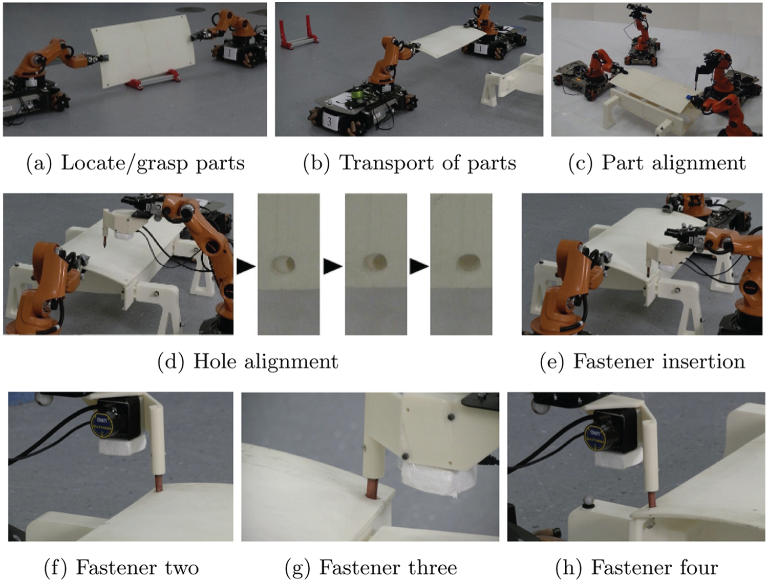
Assembly tasks involve large-scale operations such as transport and fine manipulation operations such as hole alignment and fastener insertion.
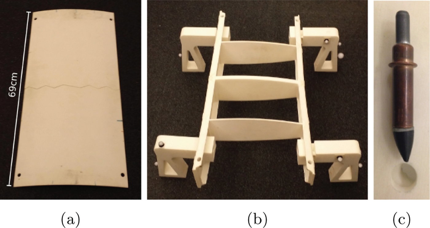
Assembly parts used in our experiments. (a) Wing panel. (b) Wing box. (c) A fastener and hole (misaligned) as used in this task. The fastener is an adapted cleco. The holes were drilled to permit a cleco to fit up to the flange with a tolerance of 1.5 mm.
In this paper we present a multi-scale perception and manipulation framework for multi-robot assembly tasks.
Multi-scale perception. In Section 5.1, we contribute a hierarchical approach in which different layers of localization and control systems interact to satisfy the continuously changing scale and precision requirements. We characterize each sensor in our system with its scope and accuracy. Then we formalize the problem of multi-scale perception as finding the sequence of sensors to use such that the system’s state can be tracked at the required accuracy through the composition of these sensors.
Our implementation is based on the integration of computer vision with other sensors.
Failure recovery. Complex assembly operations require performing a long sequence of subtasks. For the assembly operation to succeed, each subtask must succeed. Even if a system uses controllers that have very low failure rates for the individual subtasks, the combined probability of failure for the complete system can be large. Building a robust system for such long operations requires detecting and recovering from failures. We present such a failure recovery approach in Section 5.3 by extending our system’s multi-scale perception formalization. We detect when precision is insufficient for a particular operation, and move freely between adjacent levels in the perception hierarchy, allowing us to re-seed failed searches and tracking procedures with better initial guesses.
Coordinated multi-scale manipulation. A team of robots working in a factory requires coordination and collaboration. Our system displays coordination between robots at various spatial scales. We present an approach in Section 4.1 for coordination between a team of robots for transporting large structures. We also present a coordination system in Section 4.2 which enables fine manipulation skills, particularly for inserting a fastener or screwing a nut. Much like human workers, robots need specialized tools to perform these operations to specifications. In the same section we also present a tool accompanying the control algorithm which unifies sensing and actuation in the tool frame, thus delivering high precision.
In this work we present a system for autonomously assembling complex and large structures in flexible factory environments. We identify the challenges and present our solutions to build a robust, multi-robot system.
Our goal is to develop algorithms and systems which can be transferred to real factories even though the scale of the tasks, or the kinematics and dynamics of the robots, change.
Our contributions are the following:
a multi-robot mobile manipulation algorithm that uses robot-to-robot communication for complex assembly problems consisting of task assignment, cooperative transport of parts, and assembly of parts using fasteners, with an instantiation in the form of an end-to-end system for connecting an airplane wing panel to a wing box;
individual collaborative algorithms for multi-robot transport and multi-robot part assembly using fasteners;
a system with multi-scale perception, manipulation, and failure-recovery capabilities, along with a formalization of the planning problem for multi-scale systems.
As the experiments in Section 6 show, our system is robust, despite the complexity of the task and the flexibility in the environment.
2. Related work
This paper builds on important prior research on collaborative robotic systems (Mellinger et al., 2013; Willmann et al., 2012; Worcester et al., 2014), fine manipulation for assembly (Galloway et al., 2010; Komendera et al., 2014; Lozano-Perez et al., 1984), and visual perception for manipulation (Collet et al., 2011; Rusu et al., 2010).
2.1. Collaborative robotic systems
There has been recent work in developing collaborative systems for the assembly and construction of large structures. In Worcester et al. (2011) and Worcester et al. (2014) robots can either attach parts to build a complex structure or they can sense the current state of the structure using an RGB-D camera. The system displays a high degree of parallelization as well as failure recovery. With our system we focus on a task which requires collaboration between the robots during manipulation tasks as well, such as the multi-robot transport of a large wing panel and the multi-robot alignment of holes for attachment. This requires our system to be highly heterogeneous in terms of the different sensors, the manipulation operations, and also the tools used by the robots.
In Lindsey et al. (2012) and Willmann et al. (2012) assembly and construction systems consisting of flying robots are presented. Petersen et al. (2011) present a system where mobile robots can build structures and climb the structures they build. These systems provide impressive examples of multi-robot coordination in building structures that are much larger than the robots. Heger and Singh (2010) present a planner for the assembly of complex lattice structures, and in McEvoy et al. (2014), Stein et al. (2011) and Yun and Rus (2010) planners which take into account the parallelization of the assembly task and the stability of truss structures are presented. While these systems focus on using identical building blocks, e.g. bricks or truss-like structures, for the modular construction of structures, we focus on manipulating parts with shapes that are inspired from real manufacturing and assembly applications.
Different methods have been proposed for collaborative manipulation/transport of objects by a team of robots (Desai and Kumar, 1999; Khatib et al., 1996; Kume et al., 2007; Li et al., 2008; Miyata et al., 2002; Sugar and Kumar, 2002; Yamashita et al., 2003). Desai and Kumar (1999), particularly, propose a motion planning approach for a team of robots transporting an object among obstacles, and Khatib et al. (1996) present a decentralized control framework for the manipulation of an object with a system of multiple manipulators. The control problem for a team of quadrotors transporting an object (Mellinger et al., 2013) has also been studied. Similar approaches have been applied to the factory floor (Hirata and Kosuge, 2000; Lenz et al., 2008; Reinhart and Zaidan, 2009) where a team of robots transport an object with the help of human input. Our system is not structured specifically for a transport task, but is generic enough to accommodate other assembly tasks.
2.2. Fine manipulation for assembly
One generic and important assembly operation is fastening multiple parts together. In our system this is achieved by inserting fasteners through holes on the parts. This operation, sometimes called peg-in-hole in the literature, has been studied extensively. One approach to this problem is to use hybrid force-position control (Mason, 1981; Raibert and Craig, 1981) which, through force sensing and compliant motion (Inoue, 1974), enables a manipulator to slide along surfaces. Combined with a principled approach to dealing with uncertainty (Lozano-Perez et al., 1984), a high-precision operation such as peg-in-hole can be accomplished through a set of guarded-moves. This approach, however, may not be feasible if the assembly parts are very sensitive and prone to scratching. In our implementation we avoid making forceful interactions with the surfaces of assembly parts. Instead of a series of guarded moves, we use extensive and high accuracy sensor readings to localize the hole, and a compliant shape for the fastener tip to account for any remaining inaccuracy in localization.
Complete systems that can perform complex and precise manipulation tasks (Bagnell et al., 2012; Hudson et al., 2012; Righetti et al., 2014) are also presented in various robotic challenges (Balakirsky, 2010; Balakirsky et al., 2012; Hackett et al., 2013; Pratt and Manzo, 2013). These systems attempt to explore the problems associated with building complete, intelligent, and flexible manipulation systems. We share these goals but we focus on multi-robot tasks, and particularly assembly tasks which require high precision. While many of the above systems achieve precision by exploiting environmental contacts through force feedback, working with delicate assembly parts requires us to use a hierarchical system of visual and laser-based sensors to locate objects and features, to avoid scratching and damaging the parts.
Manipulation systems for different types of assembly tasks have also been proposed. Galloway et al. (2010) present a robotic system that can construct truss-like structures. Rather than using mobile robots, they propose a static system which moves the constructed structure as new layers are added. Komendera et al. (2014) investigate approaches to robotized tools which can be used to achieve precise assembly of truss structures. Rojas and Peters (2012) develop different controllers for assembly operations and analyzed their relative performances. Hamner et al. (2010) build a mobile manipulator for assembly tasks. Heger et al. (2005) investigate the application of sliding autonomy for mixed robot-human teams performing assembly tasks. Our focus is on the integration of multi-scale perception and manipulation techniques for autonomous multi-robot teams.
During long sequences of complex assembly operations, failure becomes unavoidable. The literature on failure detection and recovery starts with the geometrical models proposed by Donald (1988, 1989). Other approaches have also been proposed based on the analysis of joint torques in a robotic system (Visinsky et al., 1994). Worcester et al. (2014) propose a visual inspection approach comparing a rendered view of three-dimensional object models to a depth view from a visual depth sensor. We formalize failure recovery in the context of multi-scale perception and visual servoing.
2.3. Visual perception for manipulation
Robotic visual perception literature provides a rich set of tools which can be employed to address various problems in the factory settings, including object instance recognition (Collet et al., 2011; Tang et al., 2012), six degree- of-freedom (DoF) pose estimation (Choi et al., 2012; Rusu et al., 2010), and pose tracking (Choi and Christensen, 2012; Newcombe et al., 2011). While these systems work best when the object is closer than a few meters, the accuracy drops as the object gets too far or too close. In addition, visual perception is highly challenged in many cases, such as occlusions, cluttered backgrounds, and image blurring, because of the fast motions in either the objects or camera. To overcome these limitations of visual perception, it is often combined with motion estimation (Klein and Drummond, 2004) or tactile sensing (Allen, 1988; Ilonen et al., 2013). Skotheim et al. (2008) use functional feature detection for low-level industrial manipulation. Although the literature provides these powerful techniques, any single technique is insufficient to overcome the challenges of flexible factory environments.
3. Problem description and solution overview
We present a class of problems, which we can solve using our multi-scale sensing and coordination framework.
3.1. Problem specification
The multi-scale assembly problem consists of the following.
A set of robotic mobile manipulators. These manipulators may each be equipped with different end-effectors and tools to help complete the task.
A set of sensors, which can be moved by robots. Each sensor has two important properties: its scope, or field of view, defining the volume of the environment the sensor can view at a given moment, and accuracy, defining the upper bound on the error with which the sensor can localize a certain object or feature in its scope.
A set of assembly parts which must be put into a goal configuration.
Part feeders. A part feeder provides one or more identical parts to workers with a known configuration and bounded error. In our flexible factory setting the locations of part-feeders can change; therefore robots need to localize part-feeders in the large scale of the factory floor.
Goal configuration. The goal configuration in the assembly problem is a relative positioning of all assembly parts to within specified error tolerances.
Given a set of mobile manipulators, sensors, and part feeders, the problem is to transform assembly parts into the specified goal configuration. In other words, the robots must use the resources available to them to create a physical instantiation of the desired assembly.
3.2. Exemplar task
We present the airplane wing assembly task as an instantiation of the problem specification.
Robotic mobile manipulators. We use four KUKA youBots with five-DoF arms and parallel plate grippers. One robot gripper is augmented with a tool for detecting holes and inserting fasteners. Another robot’s gripper is augmented with a RGB-D camera. The two remaining robots are not modified.
Sensors. We are provided three sensors for use. First, we are provided a marker-based tracking system, which can perform tracking with a large scope. This sensor, however, requires markers to be placed on objects for tracking, and thus cannot directly track parts which may not be marked or tarnished. Second, we are provided a RGB-D camera which we use for medium scope tracking with medium precision. Finally, we have a laser scanner which we use for fine scale detection of fastener holes as a part of a specialized tool. Note that all of our sensing systems are subject to occlusion. Non-line-of-sight sensing could be enabled using radio-frequency identification (Wang et al., 2013).
Assembly parts. We have a miniaturized wing box (Figure 2(b)), an upper wing panel (Figure 2(a)), and four fasteners (Figure 2(c)). The assembled wing has dimensions (l × w × h)=(69 cm × 36 cm × 27 cm). The wing box and wing panel each has a hole on each corner to allow for the insertion of fasteners.
Part feeders. A rack and legs which we rigidly fix to the wing box are outfitted with markers for localization. Both can be seen in Figure 1(b). The rack and legs, along with a fastener dispenser affixed to one of the youBots, also act as part feeders.
Goal configuration. Our goal state is the alignment of the wing panel’s and wing box’s holes, with four fasteners connecting the two.
This example task enables us to explore key issues related to the future of factory automation.
Flexibility. A key component of flexibility on factory floors is the ability to rearrange part feeders, assembly spaces, and robots. Therefore, we require a rearrangeable set-up which can be tested in multiple arrangements.
Collaboration. Robots must be able to assemble large and heavy objects with masses which surpass the limits of the robots’ individual strength. The transport and alignment of the wing panel require multiple robots to collaborate.
Precision and speed. Robotic assembly systems must be able to adapt to the varying precision and speed requirements within a single task. The two subtasks, transporting the wing panel and inserting the fasteners, require our system to be able trade-off between precision and speed using a multi-scale perception approach.
Robustness. The airplane wing assembly task consists of multiple steps, each of which must be completed successfully.
3.3. Task solution overview
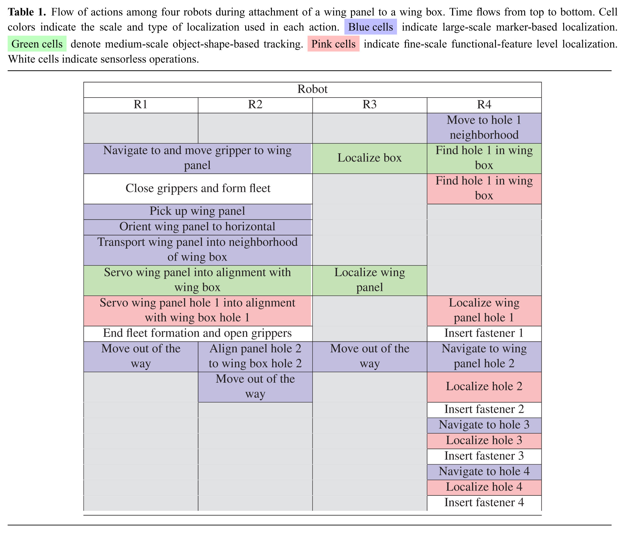
The team of robots executes the following operations to solve the assembly problem (we recommend viewing a video of the sequence of operations in Extension 1). Some of these tasks can be performed in parallel, as suggested by Table 1. In the table, the transporting robots are denoted as R1 and R2, the coarse perception robot is denoted as R3, and the fine perception robot is denoted as R4. A bird’s-eye view of the overall system can also be seen in Figure 3.
The fine perception youBot moves to the wing box feeder using the marker on the wing box feeder. Once the robot is in the neighborhood it then uses the laser scanner to search and locate one of the wing box holes.
The coarse perception youBot localizes the wing box using the RGB-D sensor.
The two transporting youBots lift a vertically oriented wing panel (Figure 1(a)) and rotate it horizontally (Figure 1(b)). Two youBots are needed since a single youBot is unable to exert the forces necessary to lift the wing panel by itself. Pose information is communicated from the marker-based detection system to the two transporting youBots.
The coarse perception robot localizes the wing panel once the panel is within the RGB-D scope. The relative pose of the wing panel with respect to the wing box is continuously communicated from the coarse perception robot to the two transporting youBots. These two robots align the wing panel above the wing box.
The transporting fleet moves the wing panel collaboratively under the fine perception robot’s laser scanner. When the hole is seen under the laser scanner, the relative pose of the wing panel hole with respect to the wing box hole is communicated from the fine perception robot to the two transporting youBots. After the two holes are aligned, the wing panel is lowered onto the wing box. If, after a search trajectory finishes, the hole is not found, it is assumed that the initial estimate was not close enough for alignment, and the youBots return to the previous step.
The fine perception youBot inserts the first fastener into the two now-aligned holes. The system now has two holes aligned and a fastener connecting them, restricting the wing panel’s movement to one DoF, rotation about the wing box surface.
The two transporting youBots open their grippers and back away from the wing box.
One of the transporting robots uses its arm to push the panel flush against the wing box, first on one side, and then on the other, along the rotational DoF to achieve final alignment.
For each of the remaining three holes, the following three sub-steps are performed in this order. (a) The fine perception youBot gets in the neighborhood of the hole using marker-based localization. (b) A search is performed to localize the hole in the laser scanner frame, aligning the laser scanner and the hole. If this step fails, it means that the error in our initial guess of the hole’s location from step (a) was high and failure recovery is triggered. (c) A fastener is inserted, securing the two holes.
Flow of actions among four robots during attachment of a wing panel to a wing box. Time flows from top to bottom. Cell colors indicate the scale and type of localization used in each action. Blue cells indicate large-scale marker-based localization. Green cells denote medium-scale object-shape-based tracking. Pink cells indicate fine-scale functional-feature level localization. White cells indicate sensorless operations.
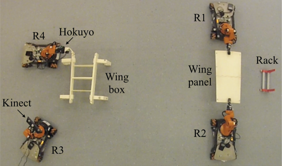
A bird’s-eye view of the overall system. The marker-based tracking cameras which surround the assembly area are not shown.
In the next section we describe the multi-scale manipulation algorithms that enable the robot team to perform these operations.
4. Coordinated multi-scale manipulation
Assembly tasks require robots to coordinate with one another to transport parts, large and small, over large distances and into millimeter-scale alignment. Here we describe both coarse manipulation and fine manipulation approaches to team formation and coordination.
4.1. Fleet control for transport
For collaborative transport of large parts, the robots perform a distributed, collective behavior inspired by human group behavior using force feedback and observation of others. In fleet control mode, the robots maintain a fixed formation of arbitrary shape while holding an object, as in Figure 4. Algorithm 1 summarizes the algorithm.
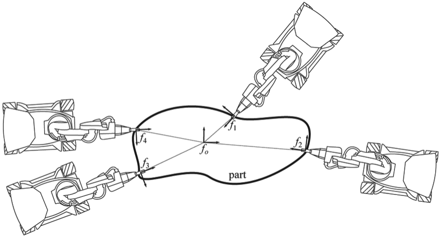
Through fleet control, an arbitrary number of robots collaboratively transporting a part in an arbitrary shape formation. Individual robot motions are computed with respect to a commanded twist at the fleet origin, o. Each robot n maintains the pose of the fleet origin in its own local coordinate frame, fn, so there is no need for a global reference. The algorithm is fully distributed.
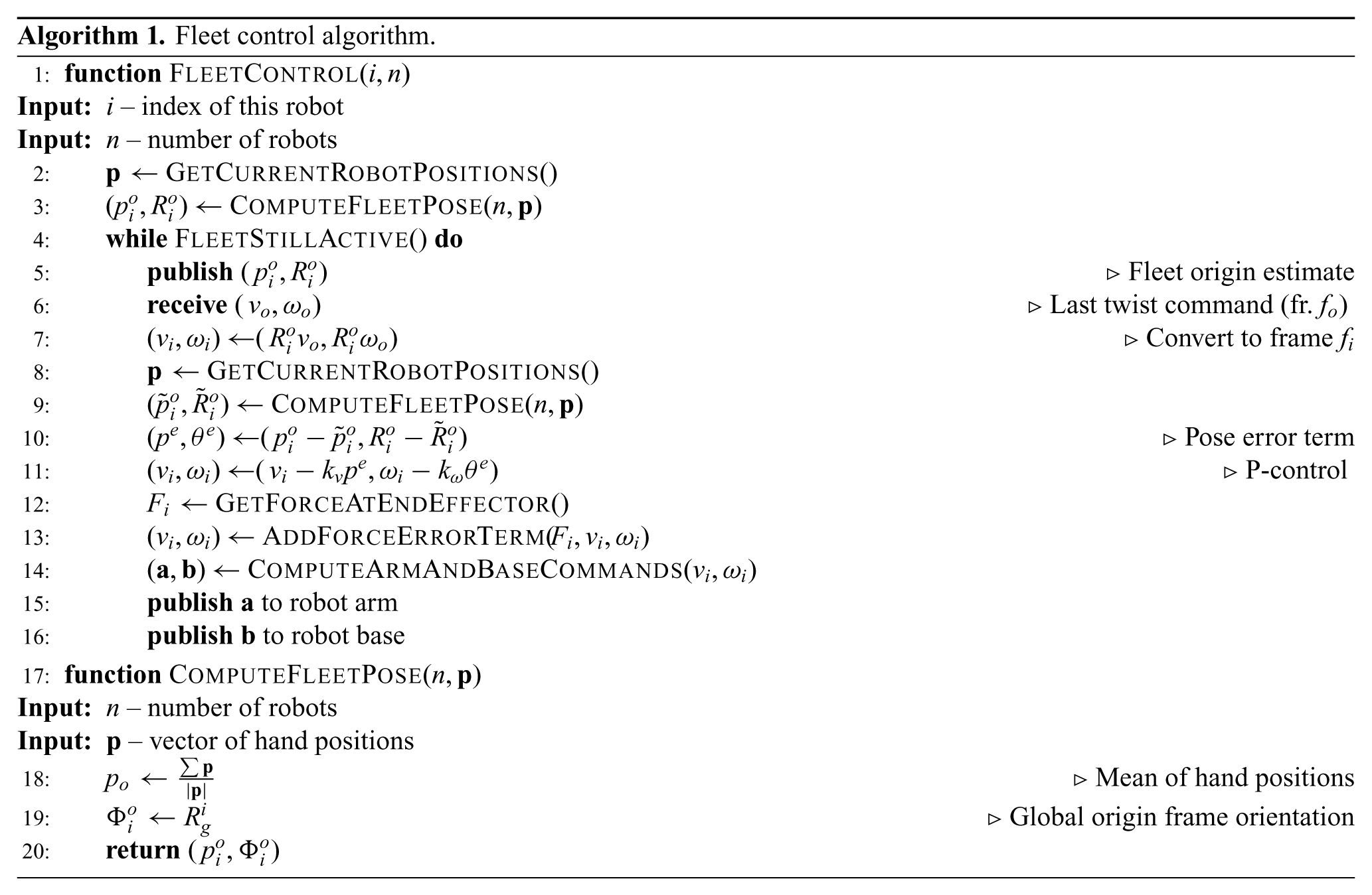
Initially, each robot separately moves into formation by grasping the object at an appropriate location. Robot i’s pose, pi, is measured at this grasp point and defines a coordinate frame fi at the robot’s hand. Formation control initializes via a synchronization broadcast message. Upon initialization, the robots compute a common reference origin fo for the object (line 3 in Algorithm 1). Robot i represents the fleet origin in its own frame as
Group motions are commanded as a twist (vo, ωo) specified in frame fo (line 6 in Algorithm 1). Each robot computes its own hand motion in order to comply with the twist command in six DoFs. Hand motions are achieved in line 14 in Algorithm 1 through base motion when possible (X, Y, yaw) and arm motion otherwise (Z, roll, pitch). It should be noted, however, that the KUKA youBot cannot achieve full six-DoF motion due to its arm kinematics. Therefore, the task presented in this paper involves only five-DoF object manipulation.
An important function of the fleet controller is to maintain a stable fleet formation. Any position error introduced by the group motion will cause the fleet origin to drift away from its target pose in the frame of the robots. A P-controller introduces correction terms to the body and arm motions in order to maintain the correct fleet formation (lines 8–11 in Algorithm 1).
Similarly, force exchange among the robots through the object can indicate an error in desired position. The robots’ arms adjust position to comply with external forces (lines 12–13 in Algorithm 1). In the steady state, an error derived from the joint torques can be attributed to a combination of gravity and an error in the fleet formation. Thus, the robot has detected a resultant force from the combined motion of the rest of the fleet. In response to this force, the fleet controller applies a correction term to
Since each robot computes a motion consistent with the fleet twist command, any residual force results from an error in the formation, which may have two causes. First, the robot may drift slightly out of formation while carrying a rigid object. Second, the object may be somewhat deformable. Although the fleet cannot deliberately exploit deformability of material, it will accommodate deformations induced by the transport operation by slightly varying the formation in response to these joint torques.
4.2. Coordinated mating of holes and fastener insertion
One critical fine manipulation skill for assembly is mating holes on parts and inserting fasteners through these holes. We use a distributed procedure and an associated tool to perform such fine operations.
To achieve millimeter-scale accuracy, we employ a custom-built end-effector tool on which both a Hokuyo laser scanner and a fastener are rigidly affixed (left-hand side of Figure 5). This sensor fulfills the functional -feature-based localization in the hierarchy.
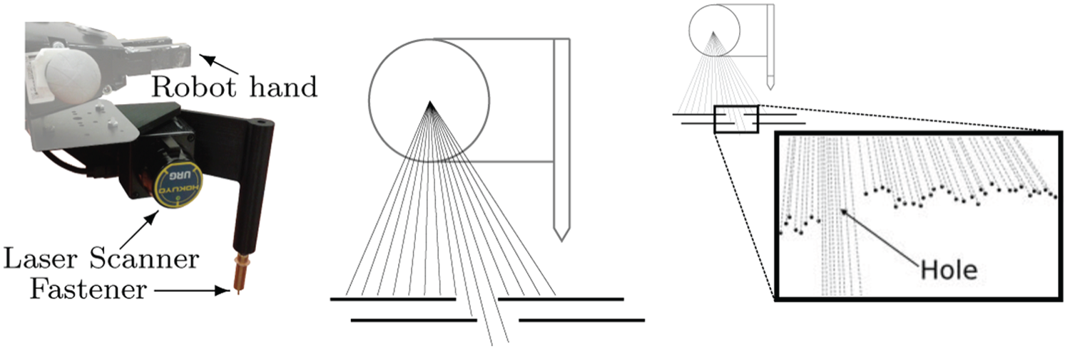
Left-hand side: hole alignment and insertion tool. Center: alignment of two holes is achieved by estimating the width of the opening. Right-hand side: example real data used to estimate the width of the opening.
Our feature detector performs filtering over the laser readings to first fit a plane to the assembly part’s surface and then to detect a hole in this plane (right-hand side of Figure 5).
We present the collaborative procedure by which our system aligns the holes of two different parts in Algorithm 2. This procedure is executed after the robot with the tool locates the hole on one of the parts (the wing box, in our example), and the fleet of robots brings the other part (the wing panel) into the vicinity using object-level tracking.
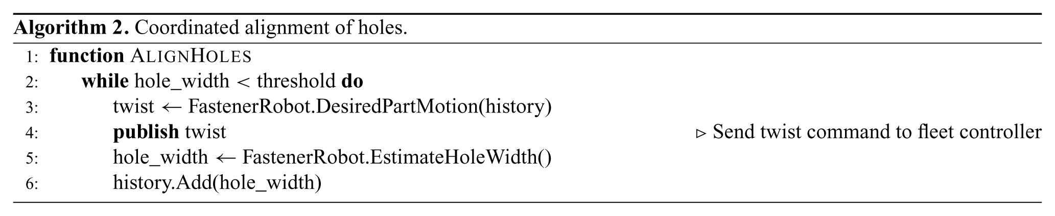
The goal in Algorithm 2 is to achieve an alignment within the tolerance required by the fastener. At each step the robot with the tool estimates (line 5 in Algorithm 2) the alignment of the two holes (center of Figure 5) by measuring the width of the opening (right-hand side of Figure 5). If the opening is not large enough (line 2 in Algorithm 2), the fastener robot commands a new velocity twist for the moving part (lines 3–4 in Algorithm 2). In computing this, the fastener robot can use the history of readings to maximize the alignment using gradient ascent. We implement this by making the fleet follow a series of waypoints.
A twist for the moving part commands the robots in the fleet to move using decentralized fleet control, in Algorithm 1. After the holes are aligned, the fastener can be inserted. The fastener is placed directly in line with the laser scan, thus allowing the robot to know exactly where the fastener is with respect to a detected hole at all times, and to bring the fastener over the hole.
The robot achieves precise alignment of two holes by decomposing in time the localization of each hole. Before the panel arrives, the laser scanner localizes the bottom hole in the box. While the laser scanner holds position, the fleet brings the panel into approximate position using other localization methods. Control then passes to the laser scanner, which commands a micro-alignment based on the remembered location of the bottom hole.
In the following section, we describe the perception and control algorithms that direct these manipulation algorithms.
5. Multi-scale perception
Perception is a critical component of the mobile manipulation system for the complex assembly of the wing. Especially challenging is the need to localize at different scales, which requires sensors that can deliver the accuracy needed at each scale. Object transport requires perception at the scale of the room. Object placement demands perception that operates at the scope of the assembly. Finally, object insertion needs perception to operate at the scope of small parts, such as fasteners. We employ three technologies to address localization at these three scales.
Marker-based technology tracks objects not in production, including parts, part sources, and robots, using a motion capture system like Vicon. Motion capture provides highly accurate, sub-centimeter localization accuracy, but it is restricted to tracking parts to which external markers may be affixed. For many production parts, attaching markers is undesirable and impractical. Furthermore, occlusion can be a problem. Thus, complementary localization methods are needed.
Object-shape-based tracking is implemented as a particle filtering approach using an RGB-D camera (Choi and Christensen, 2013). Three-dimensional mesh models of production parts are known a priori, and three visual features, colors, depth points, and normals, are used to calculate the likelihood of each particle hypothesis with respect to the current RGB-D scene. Our system localizes the wing box and wing panel from a single RGB-D camera. The robot carrying the camera can be seen in Figure 1(c), and example tracking scenes are shown in Figure 6. The system may exploit the freedom of the camera’s point of view to avoid occlusion.
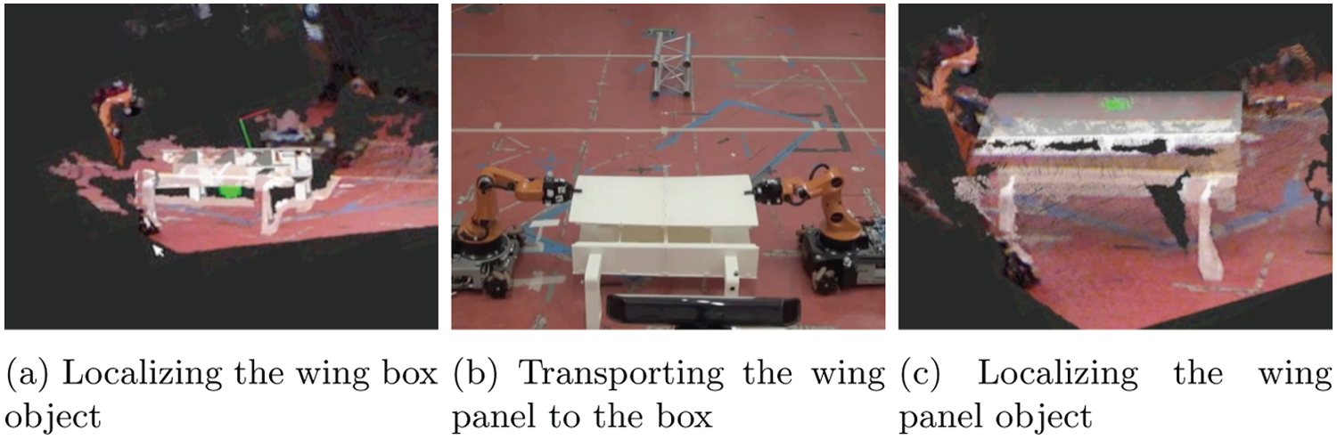
An object-shape-based tracking is employed to localize both wing box and wing panel objects as well as their relative transformation for alignment. The tracking solution is based on six-DoF particle filter and utilizes color and depth information from an RGB-D camera. Each green dot in (a) and (c) shows the origin of the object coordinate frame of each particle, and their distribution represents the posterior probability distribution of the object pose. Mean of the particles is rendered with a corresponding object CAD model.
Functional-feature-based tracking for hole alignment and insertion is the most demanding part of our task as it requires very high-precision coordination among multiple robots. We use a specialized tool with an integrated laser scanner. In our example task, the holes are the functional-features which are tracked and aligned.
We believe that without the use of all three levels in the sensing and control hierarchy, the system cannot achieve robust fastener insertion. In the rest of this section, we discuss the levels of the hierarchy and how the robots may smoothly transition up and down through them.
5.1. Sequential composition of sensors
The funnel analogy has long served in robotics literature to represent the act of reducing uncertainty or error in the configuration of an object. Mason (1985) first introduced the concept in the context of performing sensorless manipulation actions that employ passive mechanics to reduce part uncertainty. Burridge et al. (1999) applied the funnel analogy to feedback control in the form of sequential composition of controllers, producing a lot of follow-on work (Conner et al., 2003; Das et al., 2002; Tedrake et al., 2010). This body of work is sensor-agnostic in that the type and quality of sensor data is assumed to be homogeneous throughout the configuration space.
The sequential sensor composition planning problem. Given a set of n sensors, each with its own characteristics, the problem we pose is to plan a sequence of single- sensor-based servoing actions that can be composed in order to servo the target object from an initial to a goal configuration, while meeting criteria for likelihood of success and desired accuracy.
Since localization estimates are probabilistic, we compute an uncertainty volume of space by thresholding the probability density function. For example, thresholding a Gaussian distribution gives an ellipsoid describing the uncertainty of a localization estimate. Such uncertainty volumes specify the initial (I*) and goal (G*) configurations for the planning problem.
Let S = {s1, s2, …, sn} be a set of available sensors, and let
A sensor si is characterized by a tuple (vi, Ci, Ai), where vi maps the uncertainty volume, Ci, describing scope (volume of coverage) to the uncertainty volume, Ai, giving accuracy (volume of localization). These uncertainty volumes are analogous to the top and bottom of the funnel corresponding to the visual servoing controller for sensor si (see Figure 7). In the figure, the funnel’s bottom can be moved within its scope in order to satisfy a desired goal estimate.
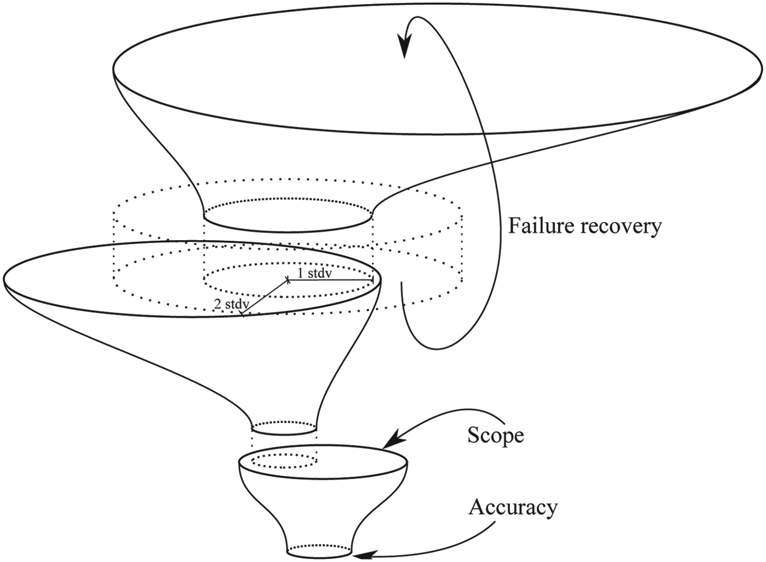
Each localization modality is represented by a funnel. The area of the mouth represents the scope of the sensor. The area of the exit represents the accuracy, as measured by the measure of the uncertainty volume representing one standard deviation from the mean estimate. Each sensor’s accuracy must be of substantially smaller measure than the subsequent sensor’s scope to avoid localization failure. In the event that the new sensor fails to detect the target object, the system must revert to an earlier stage of the localization pipeline.
A precondition of sensor-based servoing action
We leave the generalized sequential sensor composition planning problem for future work. In the factory automation setting, we propose to utilize a predefined plan. In this paper, we present a hierarchical policy with three sensors.
The composition of three sensors is as follows. When the wing panel is initially picked up from the part-feeder and transported to the wing box, the necessary scope is large but the precision requirements are coarse; for this task, marker-based localization is appropriate. Once the panel is in the vicinity of the wing box, the uncertainty in the panel pose is too high for the scope of the laser scanner. Therefore, object-based tracking is used to align the panel to the wing box such that the hole on the wing panel is in the scope of the laser scanner. Once the panel hole is in the scope of the laser scanner, the information from this sensor is used to micro-align the two holes to each other.
It should be noted that we do not perform any sensor fusion here, in which multiple independent localization estimates are combined into a higher-quality estimate. Although sensor fusion is a powerful capability, it comes at a computational cost that can, in our case, be avoided by intelligently selecting the most reliable sensor. Furthermore, sensor fusion demands careful tuning to correctly balance relative reliability of localization estimates. An incorrect tuning could easily result in a lower-quality estimate than would be provided by the most reliable sensor alone.
5.2. Error sources
Each of the localization technologies we employ imposes errors that limit accuracy in three categories: (1) sensor error, (2) indirection error, and (3) semantic calibration error. Sensor error, the accuracy claimed by the sensor manufacturer, is typically the smallest contribution to overall error in performing localization.
Indirection error stems from the fact that sensors rarely localize the desired coordinate frame directly. Instead, they sense some set of features, each with some transform to the desired frame. This indirection leads to small errors in orientation being magnified by translation. All three localization technologies exhibit indirection error.
Finally, semantic calibration error originates from the fact that a perception model used for localization must be calibrated against the semantic model used for manipulation. For example, markers placed on the robot for motion capture must be manually calibrated to the robot’s pose. Similarly, for object-shape-based tracking, the origin and shape of the CAD model of the tracked object may not match the origin and shape of the physical object. The functional-feature-based hole tracker has no semantic calibration error because the sensor directly tracks a semantic feature.
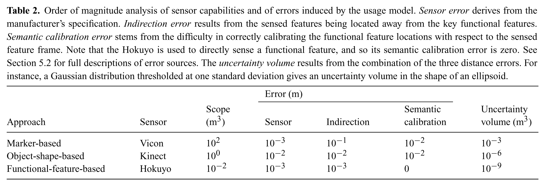
Table 2 summarizes the capabilities of our sensors. For all sensors, the indirection error dominates and determines the net accuracy.
Order of magnitude analysis of sensor capabilities and of errors induced by the usage model. Sensor error derives from the manufacturer’s specification. Indirection error results from the sensed features being located away from the key functional features. Semantic calibration error stems from the difficulty in correctly calibrating the functional feature locations with respect to the sensed feature frame. Note that the Hokuyo is used to directly sense a functional feature, and so its semantic calibration error is zero. See Section 5.2 for full descriptions of error sources. The uncertainty volume results from the combination of the three distance errors. For instance, a Gaussian distribution thresholded at one standard deviation gives an uncertainty volume in the shape of an ellipsoid.
Given a position estimate of the object with uncertainty, it may be within scope of several sensors, giving the system some flexibility in which technology to use. This flexibility allows the system to be tolerant of effects such as occlusion or communication drop-outs. The typical progression of the localized feedback control system is to servo the object into position at increasingly finer scales.
5.3. Failure recovery
Failures in execution can happen at any step of the assembly operation. To make sure that the assembly operation completes successfully, our system detects and tries to recover from failures.
The multi-scale perception/control structure provides the backbone of our failure recovery approach. During successful execution, the control is handed-off from higher levels to the lower levels: higher levels perform coarse localization and lower levels perform precise tasks. Failure recovery is implemented as the inverse process, where the control is handed off from lower levels to higher levels: lower levels of perception are precise in tracking objects/features but have limited scope, which may result in the tracked objects/features getting lost. In such a case the control is handed-off to the higher level for a coarse but large scope localization.
Formally, suppose our system executes a series of sensor-based servoing operations (vz ∘ ⋯ ∘ vl ∘ ⋯ ∘ vk ∘ ⋯ ∘ vj ∘ vi)(I*). Without loss of generality, we say that we detect a failure during the execution of vl if the state uncertainty becomes larger than Cl, the scope of sensor l. This triggers backtracking in the plan such that the previous sensor-based servoing operation, vk, which encapsulates the state uncertainty is found and the execution is restarted from there.
In our task, a crucial example of the failure recovery process occurs during alignment of the panel-hole with the box-hole. To accomplish this task, the wing panel is first aligned with the wing box using the object-shape-based perception system, which has a large scope but low accuracy. Once the wing panel is coarsely aligned with the wing box, the functional-feature-based localizer takes over to track the panel-hole and align it with the box-hole. This localizer has high accuracy but a small scope. The scanner occasionally loses track of the hole due to the small scope, the noise in the arm, and the base motions of the robots during alignment. In such a case, the system reverts back to the previous level, the object-shape-based alignment. The larger scope re-aligns the wing panel with the wing box and hands over the control to the functional-feature-based tracker once more. This process continues until this sensor successfully tracks the wing panel-hole and aligns it with the wing box-hole.
This approach to detecting and recovering from failure provides significant robustness to our system. Even if the individual layers permit failure, the overall architecture displays very high robustness as long as failures are detected and the system is started from a recoverable state.
6. Experiments
We use a team of four KUKA youBots for our experiments. These robots are tasked with assembling a wing panel (Figure 2(a)), on a wing box (Figure 2(b)), and using fasteners (Figure 2(c)). The wing panel and wing box are initially placed on supporting racks, which have markers for the marker-based Vicon tracking system. Two of the robots, R1 and R2, are responsible for the manipulation of the panel. Robot R3 carries a Kinect RGB-D camera which performs the object-shape-based tracking of the wing panel and the wing box. Robot R4 carries the insertion tool (left-hand side of Figure 5). The insertion tool has an integrated Hokuyo laser scanner which performs the functional-feature-based alignment with the holes on the wing box and the wing panel. The robots communicate using the messaging framework of the Robot Operating System (Quigley et al., 2009).
We measure the effectiveness of different components of our perception and control hierarchy by running experiments with three different configurations of this system.
Marker-based + Object-shape-based (MO): In this case, the wing panel and wing box are aligned only using the object-shape-based tracking and control. The functional-feature-based tracking, i.e. the Hokuyo laser scanner is not used.
Marker-based + Functional-feature-based (MF): In this case, the object-shape-based tracking of the wing panel and wing box is left out, i.e. the Kinect RGB-D sensor is not used. Instead, the robots remember their grasping configuration of the wing panel and assume it does not change relative to the robot hands during the course of the task.
Marker-based + Object-shape-based + Functional-feature-based (MOF): Our complete system where the objects are tracked using the Kinect RGB-D camera and the hole is aligned using the Hokuyo laser scanner.
With our system we performed two sets of experiments. First, we ran our system in the MOF configuration 22 times to measure the robustness, the contribution of our failure recovery system to the robustness, and the overall speed of our system. A video of one such run is available as Extension 1.
Second, we performed experiments to measure the contribution of the hierarchical perception architecture to the robustness of our system. In this set of experiments we created perturbations to the pose of the wing panel as it was being carried. Under these perturbations we ran our system four times in each of the MO, MF, and MOF configurations, totaling to 12 more runs.
7. Results
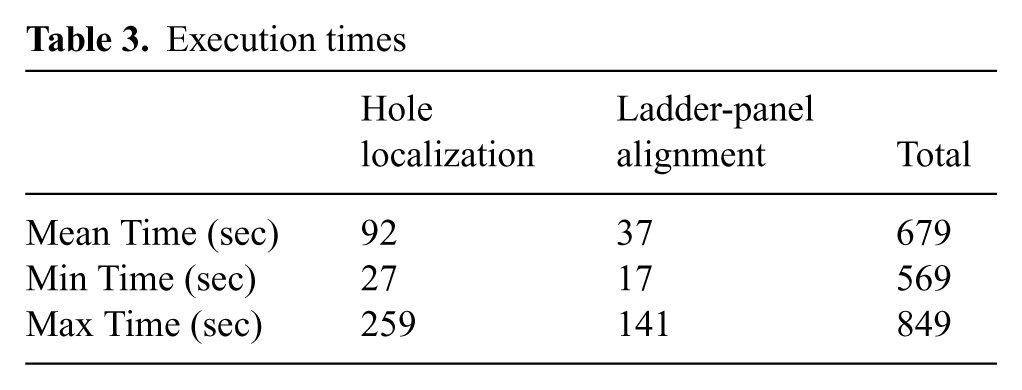
We start with reporting the results of 22 experiments in the MOF configuration. In total, the system worked 20 out of 22 times. The two failures were caused by the arms overheating due to the weight of the wing panel and the forces that arise during transport. All steps preceding and following the transport step, including any and all fastener insertions, resulted in zero failures (note that we do not consider it to be a failure if/when our failure recovery system overcomes a problem autonomously). Table 3 shows the average time of 20 successful runs along with the minimum and maximum durations. The first column shows the time spent for localizing the four holes on the assembly during each run. The second column shows the time spent during aligning the wing panel to the wing box using the object-shape-based tracking system. The last column shows the execution time for the complete assembly operation. The rest of the time is spent on transport of parts which vary according to the different starting poses of the wing panel, wing box, and robots.
Execution times
The first set of experiments also showed the important contribution of failure recovery to the robustness of our system. In 20% of wing panel alignment attempts the two holes were not aligned precisely, which resulted in failure recovery getting triggered. After failure recovery the holes were aligned and the fasteners were successfully inserted. During these experiments our system attempted 80 fastener insertions and succeeded in all of them.
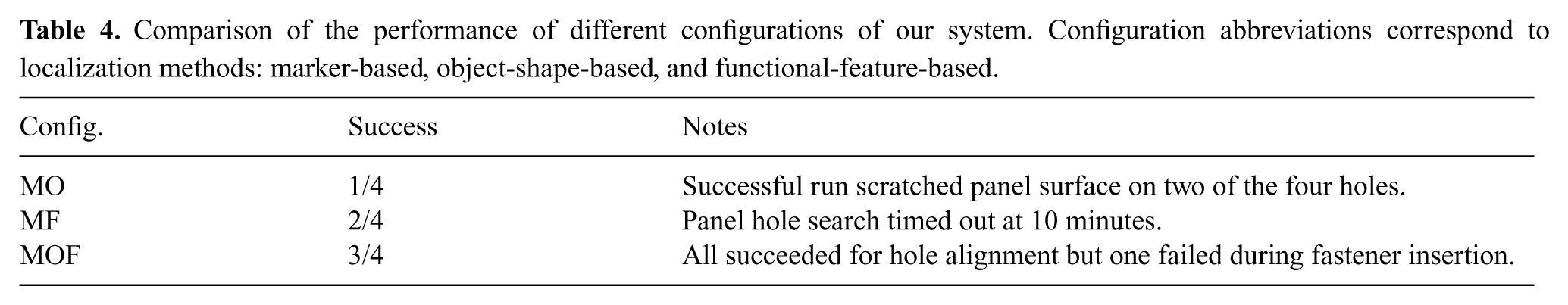
We report the result of our second set of experiments in Table 4. Here we perturb the position of the grasped panel to measure the robustness of our system. The first two cases show the system running with certain layers of the hierarchical perception system removed. In these cases the system was not able to get precise alignment between the holes of the wing panel and the wing box. The full hierarchical perception system was able to get precise alignment between the holes in all four cases, but had trouble with the insertion of the fastener since the insertion routine was not adaptive to the changed height of the panel due to the perturbation. However, our full system was robust in achieving the precise hole alignment.
Comparison of the performance of different configurations of our system. Configuration abbreviations correspond to localization methods: marker-based, object-shape-based, and functional-feature-based.
After the initial experiment which consists of 22 runs, we continued testing our system in a larger experiment including more than 100 runs. Our system displayed a similar success profile during these experiments. This confirmed the robustness and repeatability of our system.
8. Insights and conclusion
The results show that using a multi-scale approach can greatly improve the robustness of a manufacturing system to be nearly perfect. The system not only is able to perform collaborative transport, precise alignment, and collision-free insertion, but is also able to detect and fix the rare errors in alignment. Further, the only failures were in the case of high-torque-driven arm failures, in which the system failed in the collaborative transport step. In addition, we have demonstrated that using object-shape-based tracking makes the system robust to outside perturbations or other internal errors that could lead to poor grasps.
Traditional factory robots are bolted to the floor, thus achieving sensorless high precision through kinematics. Modern factory automation processes eliminate uncertainty through careful, time-consuming human design. Product changes require re-engineering of the process, contributing to a lack of versatility. Instead, we present a flexible system which can perform assembly operations with high accuracy.
The intelligent control and filtering algorithms provide flexibility but also take time (see Table 3). In our implementation, these times are significantly affected by the hardware we use. In particular, the omni-directional mecanum wheels on our robots introduce control noise during base motion, which results in longer convergence times. Reducing control noise through the use of high accuracy hardware can improve our system’s performance even further in real manufacturing environments.
The millimeter-scale precision achieved by our system is adequate for many assembly operations, but there are also other tasks in manufacturing which require higher, submilimeter, precision. There are two ways we can further improve the precision of our system. Firstly, we can reduce the control noise of our system, for example by using a different driving mechanism. Secondly, we can augment our multi-scale sensor set with a high-resolution camera capable of identifying submillimeter features.
Different sensor modalities can also be considered for other challenging tasks, such as assembling specular or transparent objects. When the passive visual perception approaches fail, active perception based on physical contact can provide valuable information. In manufacturing industry, coordinate measuring machines are the most typical contact-based dimensional inspection tools. Tactile/haptic sensors on a robotic effector can also complement inaccurate visual sensors, which is a direction we are pursuing.
Our design was guided by three principles which we think are essential for an assembly system: flexibility, dexterity, and robustness. Flexibility is what makes our system different from the factory robots of today. Part locations, part shapes, and the location of holes on the parts can change, and our hierarchical perception system is designed to identify and adapt to these changes. Dexterity refers to the wide variety of skills that an assembly system must display. Our system can perform collaborative transport, aligning of parts to each other, and fastener insertion operations, all requiring different levels of scope and precision. Robustness is a key attribute for maximizing productivity in manufacturing. As many assembly procedures consist of successive individual steps each of which must succeed, identifying and recovering from failures proved crucial for the level of robustness we required of this system.
Footnotes
Appendix: Index to Multimedia Extension
Archives of IJRR multimedia extensions published prior to 2014 can be found at http://www.ijrr.org, after 2014 all videos are available on the IJRR YouTube channel at http://www.youtube.com/user/ijrrmultimedia
System capabilities
Authors’ note
The first three authors contributed equally to this article.
Funding
This work was supported by The Boeing Company.