
Abstract
This paper presents a relaxed definition of hover for multicopters with propellers pointing in a common direction. These solutions are found by requiring that the multicopter remain substantially in one position, and that the solutions be constant when expressed in a coordinate system attached to the vehicle. The vehicle’s angular velocity is then shown to be either zero or parallel to gravity. The controllability of a vehicle’s attitude about these solutions is then investigated. These relaxed hover solutions may be applied as an algorithmic failsafe, allowing, for example, a quadrocopter to fly despite the complete loss of one, two, or three of its propellers. Experimental results validate the quadrocopter failsafe for two types of failure (a single propeller and two opposing propellers failing), and a nonlinear simulation validates the remaining two types of failure (two adjacent and three propellers failing). The relaxed hover solutions are also shown to allow a multicopter to maintain flight in spite of extreme center of mass offsets. Finally, the design and experimental validation of three novel vehicles is presented.
1. Introduction
Multicopters have found broad use as research platforms, for example, for vision-based pose estimation with quadrocopters (Fraundorfer et al., 2012) and hexacopters (Weiss et al., 2013), and also as platforms allowing for new capabilities. For example, the use of both quadrocopters and hexacopters for whale monitoring is investigated by Selby et al. (2011), hexacopters are used by Rasmussen et al. (2013) for weed research, a team of quadrocopters is used to carry a slung load by Fink et al. (2011), and an octocopter is used to calibrate radio telescope antennae by Hörandel et al. (2013). Multicopters also hold promise as goods delivery vehicles (D’Andrea, 2014).
These vehicles typically consist of an even number of propellers all pointing in a common direction, with half of the propellers having the opposite handedness from the remainder, and thus also rotating in the opposite direction. The propellers are then mechanically arranged such that the torques they produce can be made to sum to zero while the propeller thrusts support the vehicle’s weight. Differences between propeller thrusts allow the vehicle’s attitude to be changed, and the sum of the thrusts is used to accelerate the vehicle. This paper will only consider multicopters where all propellers have parallel axes of rotation (note however that alternative designs exist where this is not the case, e.g. Voyles and Jiang (2012) or Efraim et al. (2015)).
Amongst others, a motivation for using a multicopter with six or more propellers, instead of a four-propeller quadrocopter, is that the vehicle is able to maintain normal flight if one of the propellers fails (see, for example, Scaramuzza et al. (2014) for a hexacopter design and Marks et al. (2012) for an octocopter rotor failure strategy). The need for having more than four propellers follows from the requirement that the vehicle be able to hover with zero angular velocity even after the failure of one of the actuators.
In this paper, this requirement of having zero angular velocity is relaxed, and instead hover solutions are searched for during which the position remains approximately constant, and where the solutions may be described with constant parameters; these relaxed hover solutions form a superset of those typically used for multicopters. This means that the vehicle may rotate at a constant velocity in hover. They allow for the design of novel hover-capable vehicles and may also be employed to offer redundancy for multicopters experiencing an actuator failure. Since the solutions are constant in the body frame the powerful techniques of linear time-invariant systems theory may be applied for analysis and control design.
An approach is presented to formulate and solve for such relaxed hover solutions and for designing linear time-invariant controllers to control a hovering vehicle. This approach is used to compute solutions for a quadrocopter experiencing any combination of up to three complete propeller failures. For two of the cases, experimental validation is provided, while the approach for the remaining two types of failure is validated in a nonlinear simulation. The case of losing two opposing propellers is investigated in detail, with a specific focus on vehicle mass and aerodynamic properties that would render the vehicle uncontrollable.
The approach may also be used to control a multicopter where the center of mass is located far from the propellers’ geometric center. A specific example is given for a quadrocopter with an eccentric center of mass, where the conventional hover solution of zero angular velocity requires infeasible motor forces. However, by allowing the vehicle to rotate, a feasible solution is found, even if the center of mass lies outside of the propellers’ convex hull.
The methods presented are also applied to design novel, rotating body vehicles. A family of such vehicles, called “spinners,” is presented, where each vehicle comprises a number of propellers arranged in a rotationally symmetric pattern about the vehicle’s center of mass, and all propellers have the same handedness and rotate in the same direction. At hover these vehicles rotate at a high angular velocity, in the opposite direction of their propellers. A two-, three-, and four-propeller spinner is presented. In addition to their dynamic properties, when equipped with a camera, such a vehicle could be used as a low-cost omnidirectional flying camera, similar to, for example, Haus et al. (2013) or Youngren et al. (2009); note however that the spinners tend to rotate at higher velocity than the vehicles in these references, such that motion blur might present a problem.
1.1. Related work
A survey on fault detection and diagnosis and fault-tolerant control strategies for unmanned rotary wing vehicles is given by Zhang et al. (2013), and examples of commercial solutions are the emergency parachutes of Fruity chutes (2014) or those described by Dronologista (2014). Partial failure of a quadrocopter actuator is investigated for example in Chamseddine et al. (2012), Izadi et al. (2011) and Ranjbaran and Khorasani (2010). Complete propeller failure of a single propeller of a quadrocopter is investigated in Akhtar et al. (2013), Freddi et al. (2011), and Lanzon et al. (2014), where the strategy is to give up controlling the vehicle’s yaw angle, and use the remaining propellers to achieve a horizontal spin. A flight strategy to cope with an actuator failure on an octocopter is presented in Marks et al. (2012), and a hexacopter design with a focus on actuator redundancy is presented in Achtelik et al. (2012).
The failsafe method presented in this paper extends those above by finding solutions when using fewer than three propellers. Furthermore, this paper presents a family of solutions when using only three propellers (such as a quadrocopter having lost one propeller); the user may thus select the solution most appropriate to the vehicle and the situation.
The controllability of a flying, rotating vehicle with three mutually orthogonal propellers is analyzed in Kataoka et al. (2011) and a circular flight path for this vehicle is designed for it in Kataoka et al. (2013). The vehicle concept uses forward-tilted propellers to induce rotation of the vehicle, so that the vehicle then also spins about an axis, similarly to the spinners proposed in this work.
This paper will focus on vehicles that do not rely on aerodynamic effects (apart from drag and the propellers) for their stability; this is in contrast to maple-seed-like vehicles such as the Samara (Ulrich et al., 2010), or vehicles like the Spincopter (Orsag et al., 2013).
This work follows on from a conference paper published previously (Mueller and D’Andrea, 2014) and extends the results by:
presenting a more detailed derivation of the salient effects acting on a multicopter;
deriving general conditions of the hover solutions without assumptions of the number of propellers, the locations of the propellers, or the mass distribution of the vehicle;
likewise deriving a general framework for establishing attitude controllability;
considering, additionally, the failure case of a quadrocopter losing two adjacent propellers;
showing how the relaxed hover solutions may be applied to multicopters with large center of mass offsets; and
presenting the design of three novel multicopters.
1.2. Notation
Boldface symbols like
1.3. Organization
This paper is organized as follows. In Section 2 the dynamic model of a generic multicopter is presented. Hover solutions are derived in Section 3 and the controllability of the vehicle about these solutions is investigated in Section 4. The approach is applied as an actuator failsafe for quadrocopters in Section 5 and applied to a quadrocopter with a large center of mass offset in Section 6. A novel family of multicopters is presented in Section 7, and the paper concludes in Section 8.
2. Multicopter modelling
This section derives the equations of motion for a multicopter, with a special focus on the attitude dynamics. A model for the thrust force, reaction torque, and mechanical power consumption of a propeller is also presented. The equations are used in later sections to solve for hover solutions, and the power consumption of the propellers is used to compare different solutions.
Figure 1 shows a multicopter with Np = 3 propellers. The multicopter has a total mass m (including propellers), and its position relative to some point fixed in an inertial frame is expressed as
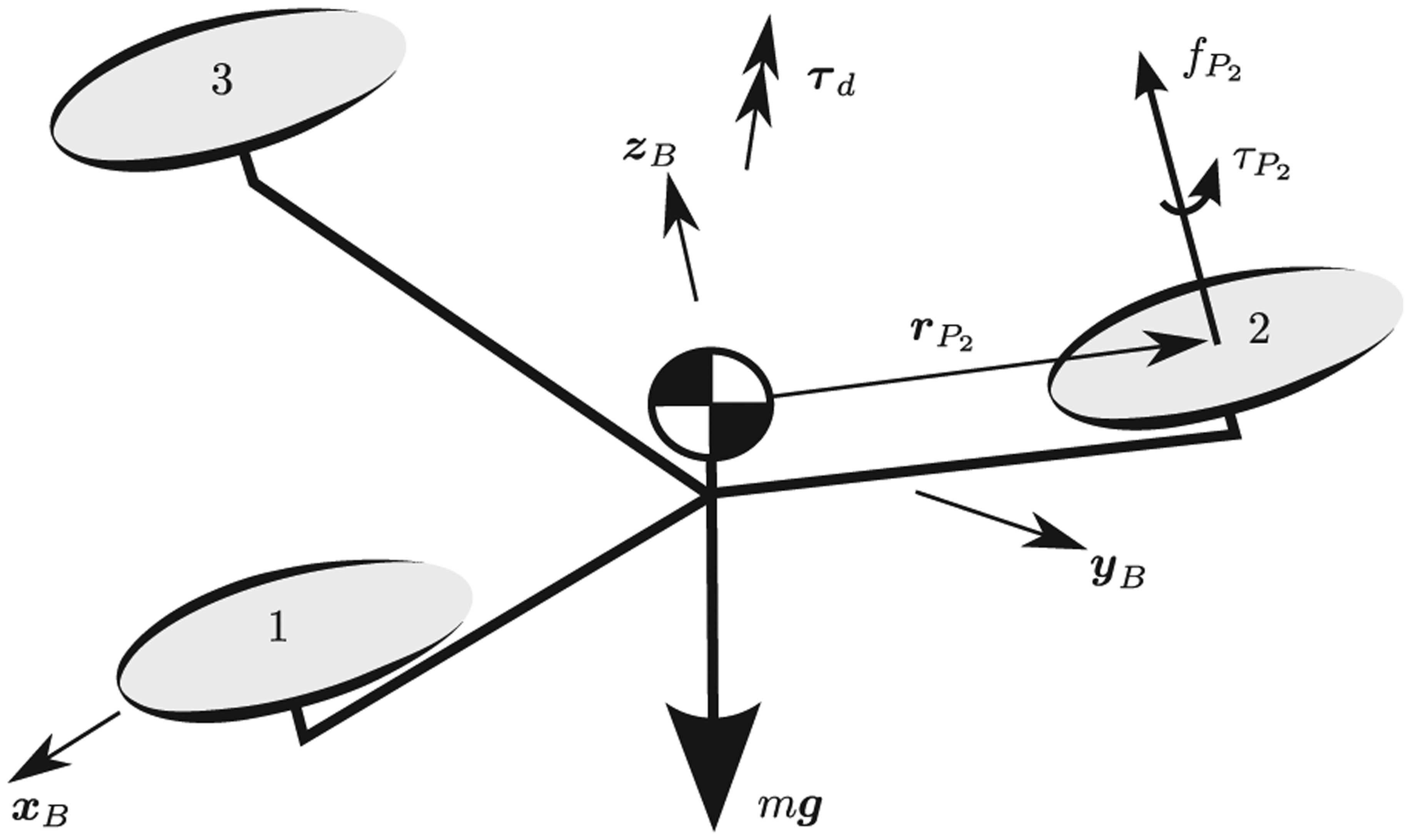
A multicopter with three propellers, showing the definition of the symbols used to derive its dynamics equations. The axes of rotation of the propellers are parallel, and are fixed with respect to the body.
The scalar thrust force
In addition to thrust, each propeller produces a scalar reaction torque
It will be assumed that the vehicle travels at low translational velocities, such that translational drag forces may be neglected. For a discussion of such effects see, for example, Martin and Salaün (2010). As a result of the multicopter’s angular velocity, a drag torque
The translational dynamics of the vehicle, expressed in the inertial coordinate system E, may now be composed as (Zipfel, 2007)

The orientation of the body with respect to the inertial reference frame is captured by the coordinate transformation matrix

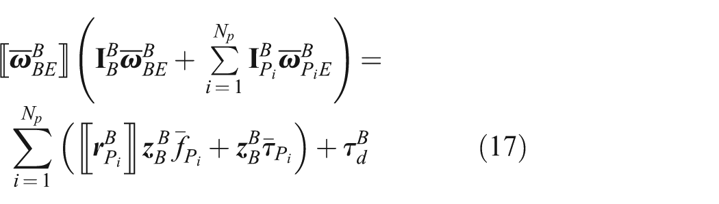
where 〚
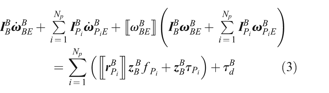
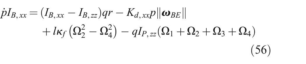
The first two terms are the time derivative of the vehicle’s and the propellers’ angular velocities with respect to the inertial frame, as expressed in the body-fixed frame. The third term expresses the cross-coupling of the angular momentum in the system, due to taking the derivative in a non-inertial frame. The right-hand side of the equation represents all the moments acting upon the body, consisting of the propeller forces acting at a distance from the center of mass, the propeller reaction torques, and the vehicle drag torque.
2.1. Propeller model
It is assumed that the pitch of each of the propellers is fixed and that a given propeller’s thrust and torque are functions only of the propeller’s angular velocity with respect to the air. Specifically, these functions are taken to be proportional to the square of the angular velocity (Pounds et al., 2002), and the air is assumed to be stationary with respect to the inertial frame. The thrust and torque are then characterized by the propeller coefficients


with
The propeller’s scalar speed

Note that this is a very simple propeller model, neglecting, for example, the translation of the propeller’s center. An example of a more complicated model is given by Martin and Salaün (2010), where a relationship between a quadrocopter’s translational motion and a horizontal propeller force is given. Such effects are here assumed to be small disturbances, which will be compensated by feedback control.
Power consumption. The mechanical power consumed by a propeller may be computed as the product of the torque it produces and the angular velocity of the propeller with respect to the body, as given by

The mechanical power is used in later sections to compare the efficiency of different hover solutions. This model may be extended, for example, with information about the electrical efficiency of the vehicle’s powertrain to compute the power required for the vehicle to hover.
2.2. Rotational drag model
The aerodynamic drag torque
Here it is assumed that the magnitude of the torque is quadratic in the vehicle’s angular velocity

where
3. Hover solutions
The conventional hover condition for a multicopter is at zero acceleration and zero angular velocity, with the thrust vector pointing opposite to gravity. For a symmetric quadrocopter in hover, for example, this implies that each motor produces a force equal to one quarter of the vehicle’s weight. The propellers’ angular momenta then sum to zero, so that the vehicle also has zero total angular momentum in hover. In this situation, the cross coupling in (3) disappears and the vehicle’s dynamics in the three translational directions decouple to first order at the equilibrium. An example of a control design for a quadrocopter can be found in Mahony et al. (2012).
The definition of hover is relaxed to include flight conditions where the vehicle remains substantially at one point in space, where the vehicle may have non-zero angular velocity. The translational acceleration may likewise be non-zero, but must average to zero for the vehicle to remain substantially in the same position. Only solutions which are constant when described in a body-fixed frame will be considered, with, specifically, the propellers’ angular velocity and the vehicle’s angular velocity being constant. These solutions are then time invariant, allowing for the design of time-invariant controllers. The rich literature and powerful tools available for the design and analysis of linear time-invariant systems may then be applied. Such a hover solution can be fully described by Np + 6 variables: the Np propeller speeds, three components of the vehicle’s angular velocity, and three components of the vehicle’s orientation.
3.1. Non-zero angular velocity during hover
If a multicopter’s angular velocity with respect to the inertial frame
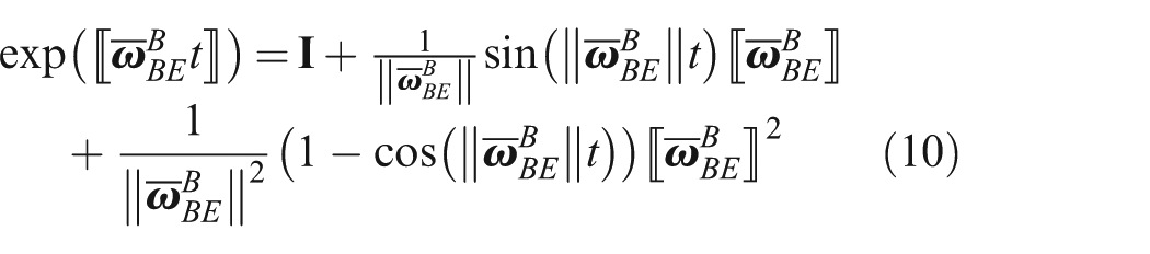
For a constant non-zero angular velocity the orientation of the body with respect to an inertial frame at time t may be solved for in closed form from (2) as

where exp(·) is the matrix exponential. An overbar will be used to denote variables that are constant at the hover solution, such as
Using Rodrigues’ formula (Shuster, 1993) and interpreting
where
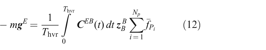
Since all other quantities are constant, the acceleration of the vehicle in hover must also be periodic, with period Thvr. The average acceleration of the vehicle can be calculated by averaging (1) over one period, where the time varying quantities have been made explicit below
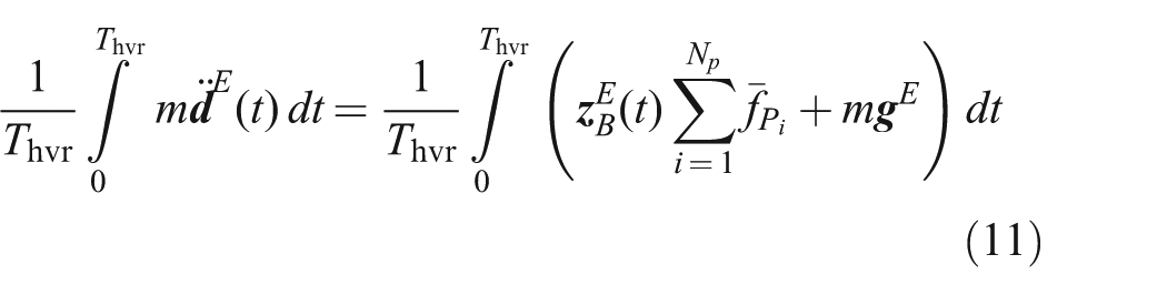
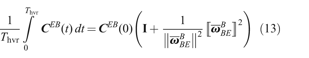
Transforming
The integral on the right-hand side may be thought of as the average coordinate transformation of the vehicle, and can be solved for by substituting equations (9) and (10)
Substituting and simplifying yields
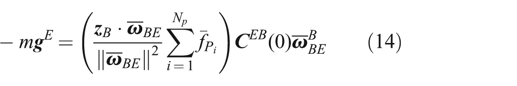
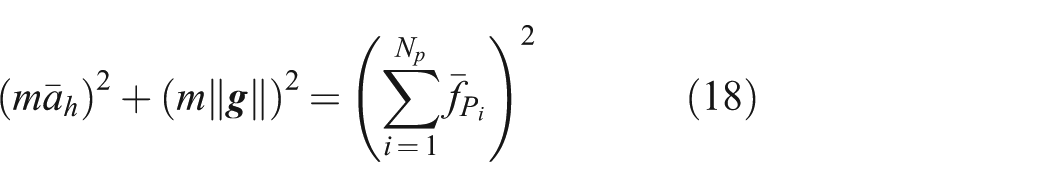
A requirement on the total thrust produced can be derived from the above by applying the Euclidean norm
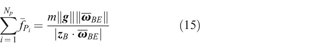
Note that this assumes that the sum of the propeller forces is positive.
Substituting (15) into (14) yields the condition that the angular velocity must be parallel to gravity in hover at time zero
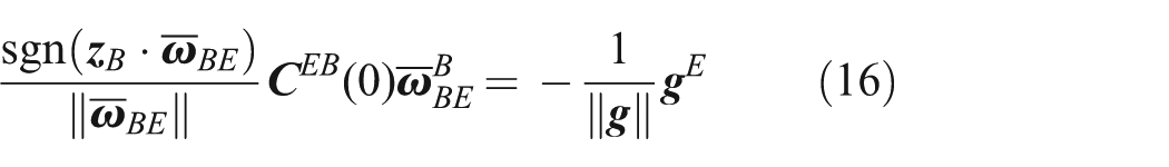
where sgn(·) is the signum function returning the sign of its argument. As it is constant, for any hover solution with constant angular velocity and constant motor forces, the angular velocity always remains parallel to gravity. This also implies that the vehicle’s vertical acceleration is always zero in hover.
Given some angular velocity
with
There are then seven constraints for the Np + 6 unknowns, leaving Np − 1 degrees of freedom for the hover solution. These degrees of freedom may be determined, for example, by finding the hover solution that requires a minimum of input power, by symmetry considerations, or by considerations related to the controllability of the system.
3.2. Position trajectory
The vehicle’s acceleration in hover will either be constant or be periodic with period Thvr. Specifically, if the vehicle’s thrust axis
This can be rewritten as a centripetal acceleration of radius
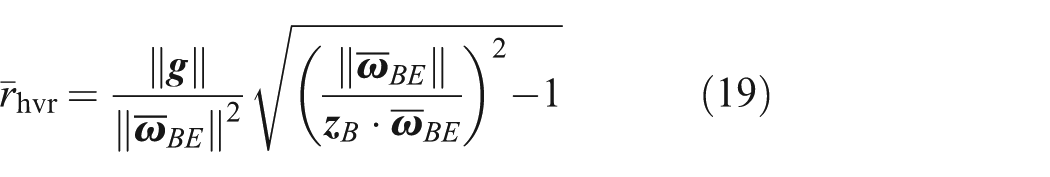
The vehicle will thus move along a horizontal circle of this radius at the hover solution.
4. Position and attitude control
A given hover solution is only useful if the vehicle can enter the solution, and maintain it in the face of disturbances. In this section an approach is given to investigate the controllability of the vehicle about a hover solution. The problem is broken into two sections for ease of analysis. First it is argued that attitude control under constant total thrust is sufficient for position control. An approach is then given for determining the controllability of the attitude system, where the problem is reduced to investigating the controllability of a linear time-invariant system with five states and NP − 1 inputs. An example cascaded controller is shown in Figure 2.
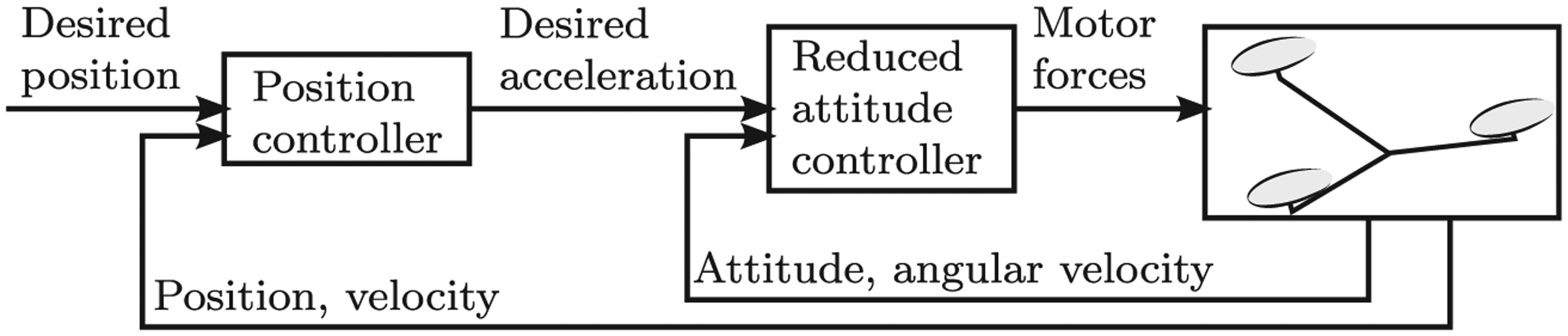
An example cascaded control strategy, where an outer position controller defines a desired acceleration and an inner controller controls the vehicle’s attitude so that the acceleration is achieved.
4.1. Position control
If both the angular velocity and the total thrust force are constant over one rotation, the average acceleration
Rather than directly finding an equation for
The second unit vector
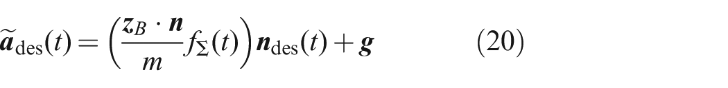
Note that the factor (
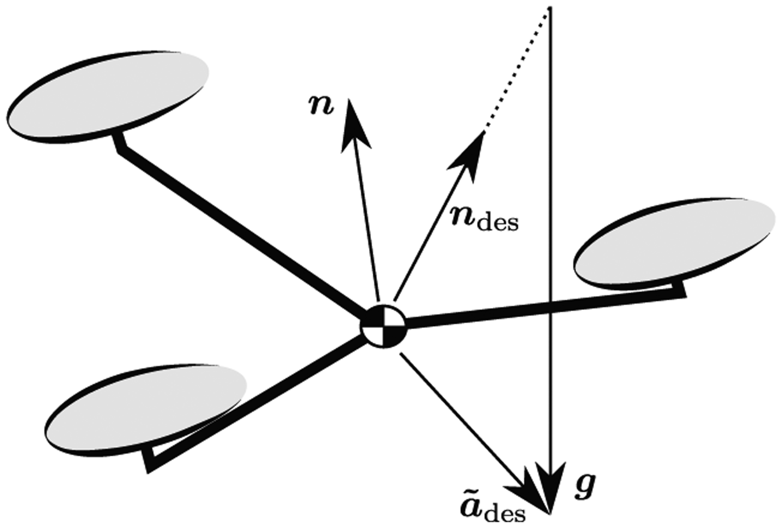
The relationships of the vectors introduced for the position control, where the desired acceleration vector
Therefore, if the body-fixed vector
4.2. Reduced attitude control
Only the two attitude degrees of freedom relevant to the vehicle’s translational motion are controlled, i.e. the unit vector

The remaining degree of freedom of

The time derivative of

The change in direction of the desired acceleration vector from (20) is captured by
The components ηi are introduced, such that

If ξ is stabilizable for some given fΣ, the vehicle is stabilizable about the desired acceleration. 1
Selecting input variables. Because the total thrust is fixed at fΣ, there are Np − 1 free input variables remaining, which may be used to control the attitude. These may be specified by introducing the input vector u and then specifying the motor forces as

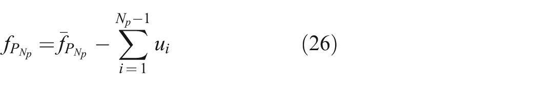
The propeller speeds (instead of thrusts) may alternatively be used as inputs through the relationships of Section 2.1. The inputs may also be based on symmetry properties of a specific vehicle, so that, for example, independent torques are used as inputs, from which the required propeller speeds are recovered (as is commonly done when controlling quadrocopters, e.g. Mahony et al. (2012)).
Linearized system. The time derivative
The effect of the angular acceleration of the propellers with respect to the body,
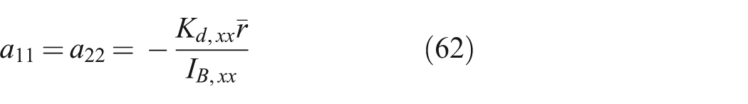
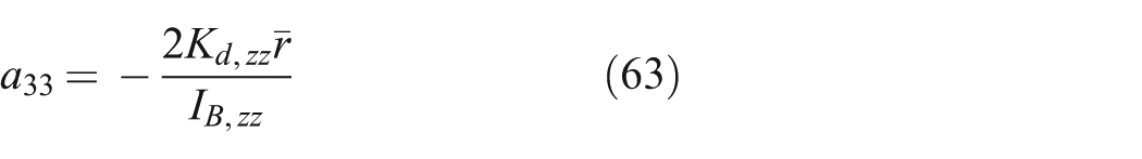
Linearizing about the hover solution yields a system as below
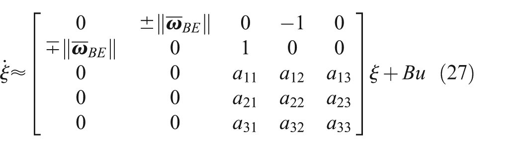
where aij, B, and u depend on the specific vehicle configuration, and follow in part from (3).
The requirement that (27) be stabilizable adds an additional criterion to the search for suitable hover solutions for a vehicle, in addition to the seven algebraic constraints derived in Section 3. Furthermore, (27) may serve as a basis for linear time-invariant controller design: in Section 5 controllers are designed for a quadrocopter experiencing propeller failures, and in Section 7 controllers are designed for novel vehicles.
5. Quadrocopter actuator failsafe
Quadrocopters are popular as research testbeds, toys, and sensor platforms (e.g. for aerial photography). Compared to hexacopters or octocopters, which have six or eight propellers, quadrocopters are mechanically simpler and have to carry less structural mass (which in turn may make them more efficient). However, they do not offer an obvious hardware redundancy if a propeller fails (that is, they cannot hover at zero angular velocity after losing a propeller).
In this section it is shown that quadrocopters can maintain a hover as defined in Section 3, after the complete loss of a propeller. In fact, under some restrictions on the vehicle’s mass distribution and aerodynamic properties, the vehicle remains controllable after the loss of any number of propellers, as long as a single propeller remains operable.
Five different quadrocopter failure scenarios are considered:
no failure;
failure of a single propeller;
failure of two opposing propellers;
failure of two adjacent propellers; and
failure of three propellers.
The hover solutions will first be presented for each, followed by controller design, and then each scenario is validated in a non-linear simulation. For losing a single propeller, and losing two opposing propellers, the simulation is validated by experiment. Extension 1 shows a video of a quadrocopter in flight after the loss of a single, and two opposing propellers.
This section focuses on controlled flight near hover in a controlled environment, rather than discussing practical implementation issues related to using these hover solutions on an actual quadrocopter in the field. For fault detection strategies, the reader is referred to the references in the introduction. Low-cost and robust sensing/estimation strategies for rapidly rotating vehicles and robust transitions from one flight mode to another may be promising areas of future research.
5.1. Platform
The work is validated using quadrocopters based on the Ascending Technologies Hummingbird (Gurdan et al., 2007), in the Flying Machine Arena (Lupashin et al., 2014), which will be referred to here simply as “the quadrocopter.” Such a quadrocopter is shown in Figure 4.
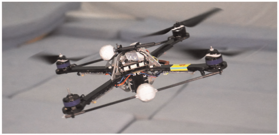
The quadrocopter used for the experiments, maintaining controlled flight despite the complete loss of one propeller.
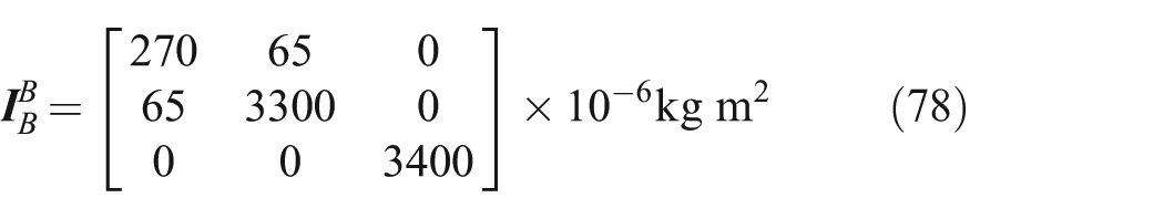
The vehicle’s mass was measured to be 0.50 kg, and the distance from the center of mass to the center of the propellers is 0.17 m. The quadrocopter’s inertia was determined from a CAD model, and validated by measuring its period of oscillation when suspended around three different axes. The inertia matrix was estimated to be

The propeller inertia about its axis of rotation was estimated by approximating the propeller and motor rotor as disks and cylinders, respectively. The remainder of the inertia matrix is neglected, so that the propeller’s inertia is constant when expressed in the body-fixed frame

The propellers used were characterized using a force-torque sensor, and the thrust and reaction torque coefficients were estimated as
The aerodynamic drag torque acting on the body was estimated to be diagonal in the body-fixed frame, with entries experimentally identified as

5.2. Hover solutions
Two short-hand notations will be used in this section. The total mechanical power consumed by the propellers will be expressed as
All configurations with more than one remaining functional propeller have at least one degree of freedom in selecting a hover solution. In such cases, numerical optimization is used to find the hover solution that uses least mechanical power, as computed in Section 2.1.1. Depending on the application, minimizing other variables may be more useful, e.g. minimizing the vehicle’s total rotation rate, or maximizing the minimum distance from the equilibrium propeller speeds to the actuator limits.
No failure. For the quadrocopter with no propellers having failed there are three degrees of freedom for finding a hover solution. As expected, the minimum power solution is to have all propellers turning at angular velocities of equal magnitude and specifically


Failure of a single propeller. Without loss of generality it will be assumed that propeller 4 has failed, that is the propeller pointing to the right if looking at the quadrocopter from the top. In this case the constraint


Some intuition for this may be gained by constraining
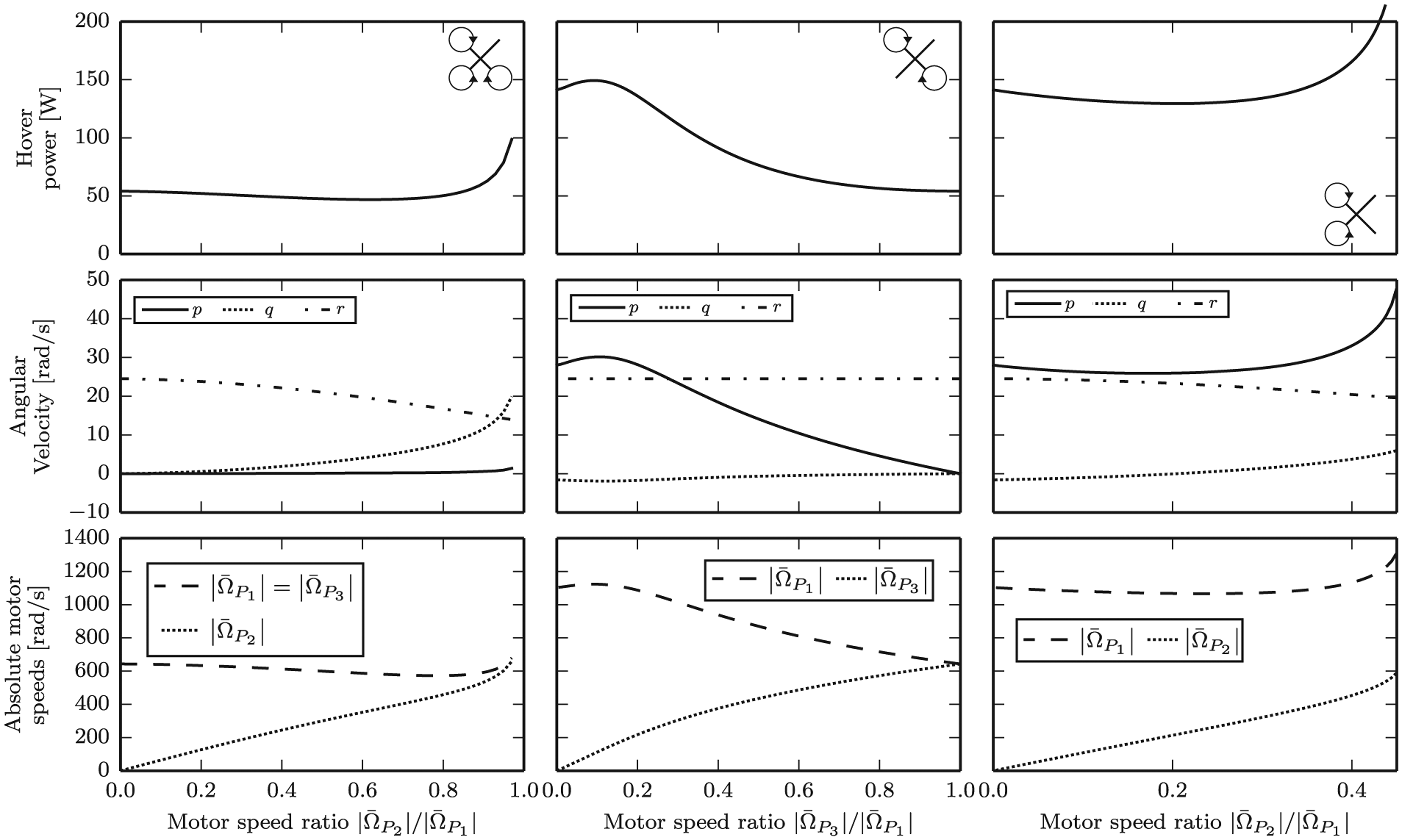
Hover solutions for different failure scenarios, from left to right: failure of a single propeller, failure of two opposing propellers, and failure of two adjacent propellers. The graphs depict how the hover solutions vary as a function of the ratio of angular velocities of the remaining motors. For the single failure, solutions may also be found where the odd propeller turns faster than the two propellers with the same handedness; these are not shown as they consume significantly more power than the solutions shown. For both scenarios of two propellers failing only half of the possible solutions are shown with the remainder following by symmetry, e.g. for two opposing propellers failing, hover solutions exist with
Failure of two opposing propellers. Here it will be assumed that the left- and right-hand side propellers have failed, so that


Failure of two adjacent propellers. If both the right-hand side and rear propellers have failed, the two added constraints are


Note that a symmetric solution exists for
Failure of three propellers. If all but one propeller have failed, there are no degrees of freedom remaining in the hover solution. It will be assumed that only the front propeller remains, and the hover solution is then


Note that it is unlikely that any practical quadrocopter has sufficient excess thrust that a single propeller is able to produce the force required.
5.3. Control and validation
The controllability of the vehicle about the hover solution is investigated for each of the five different failure cases presented above. If at least two propellers remain the method of Section 4 was used directly. For the case of losing three propellers (and thus only a single propeller remaining) the method was modified to use the single remaining force as input. In this case, the total force cannot be controlled independently of the attitude. The layout of the controller is shown in Figure 6, showing the arrangement of the cascaded position and attitude controllers. The controllers are described in more detail below.
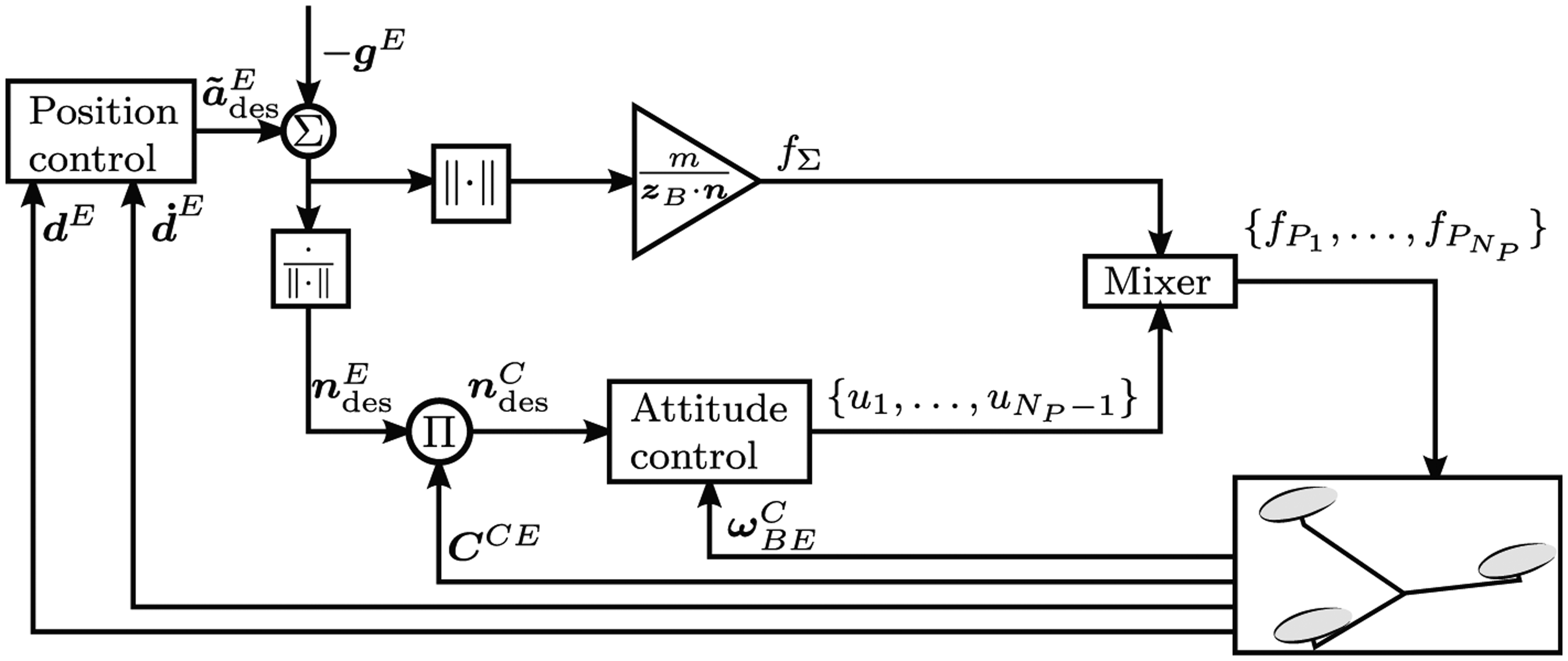
The feedback structure used for the experiments. The position controller computes a desired average acceleration
Position control. A position controller was created which calculates a desired acceleration based on the vehicle’s current position and velocity, such that the vehicle’s position behaves as a damped second-order system (Dorf and Bishop, 2008). This desired acceleration can then be substituted for the desired average acceleration in (20), and be transformed into a desired vehicle direction
Attitude control. Given a linearized attitude system of the form (27), a linear quadratic regulator (LQR) controller (Anderson and Moore, 2007) was designed for the attitude system. The same LQR weights are used for each failure scenario. The cost on deviations from the desired normal was set to 20, and the cost on the angular rates set to zero. The input cost was set to the identity matrix of the appropriate size, with units N−2.
The five-dimensional attitude subsystem (27) is stabilizable for each scenario and is controllable in each case except for two opposing propellers failing. In this case, for the given hover solution, the vehicle’s angular velocity about
Simulation results. The control strategy is validated in a nonlinear simulation for each of the different failure scenarios. No sensor noise or external disturbances are simulated. The actuators are simulated to have additional dynamics, so that the propeller speeds respond as a first-order system with time constant 15 ms.
A comparison of the flight performance for each failure scenario in simulation is shown in Figure 7. The data starts with the vehicle at the hover attitude, but with a 1 m horizontal position offset. In each scenario, the vehicle is able to stabilize its position at the origin.
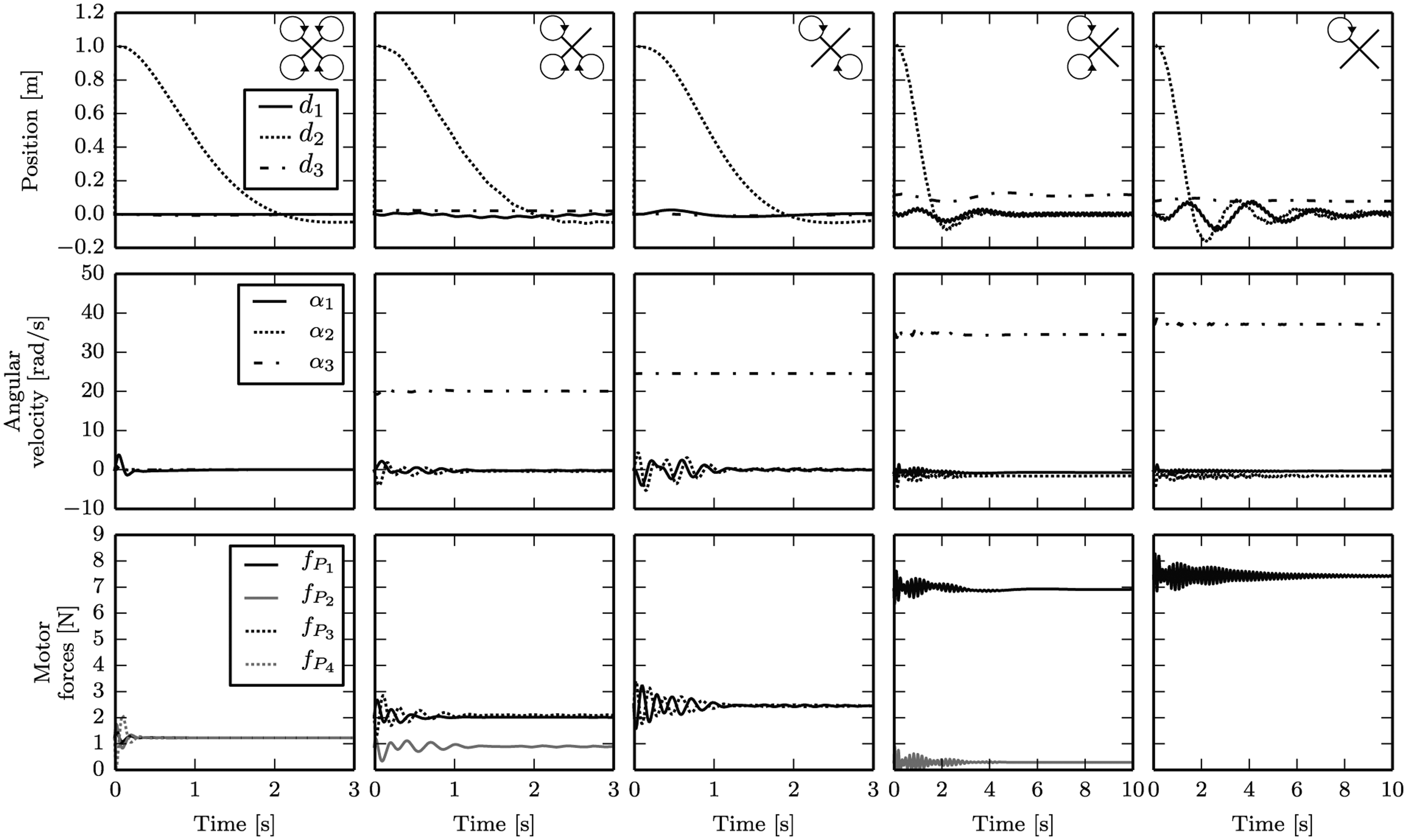
Simulation results for a quadrocopter recovering from a 1 m horizontal position error for different failure scenarios. Each column represents a different failure condition, from left to right: no failure (nominal operation), failure of a single propeller, failure of two opposing propellers, failure of two adjacent propellers, and failure of three propellers. Note that the angular velocity is expressed in the control frame C, so that two components must be zero at equilibrium. The position is expressed as
5.4. Experimental validation
The simulation is validated by comparing it to data collected from flight experiments in the Flying Machine Arena. The vehicle’s state is estimated using position and orientation measurements from a motion capture system and inertial sensors on the vehicle. A video of such experiments can be found in Extension 1. These experiments are only possible for the scenarios of no failure, failure of a single propeller, and failure of two opposing propellers; for the remaining cases (two adjacent propellers failing or three propellers failing) the quadrocopter of Section 5.1 can not produce sufficient thrust to compensate for the vehicle’s weight. The data for a single propeller failure are compared in Figure 8, and for the failure of two opposing propellers in Figure 9.
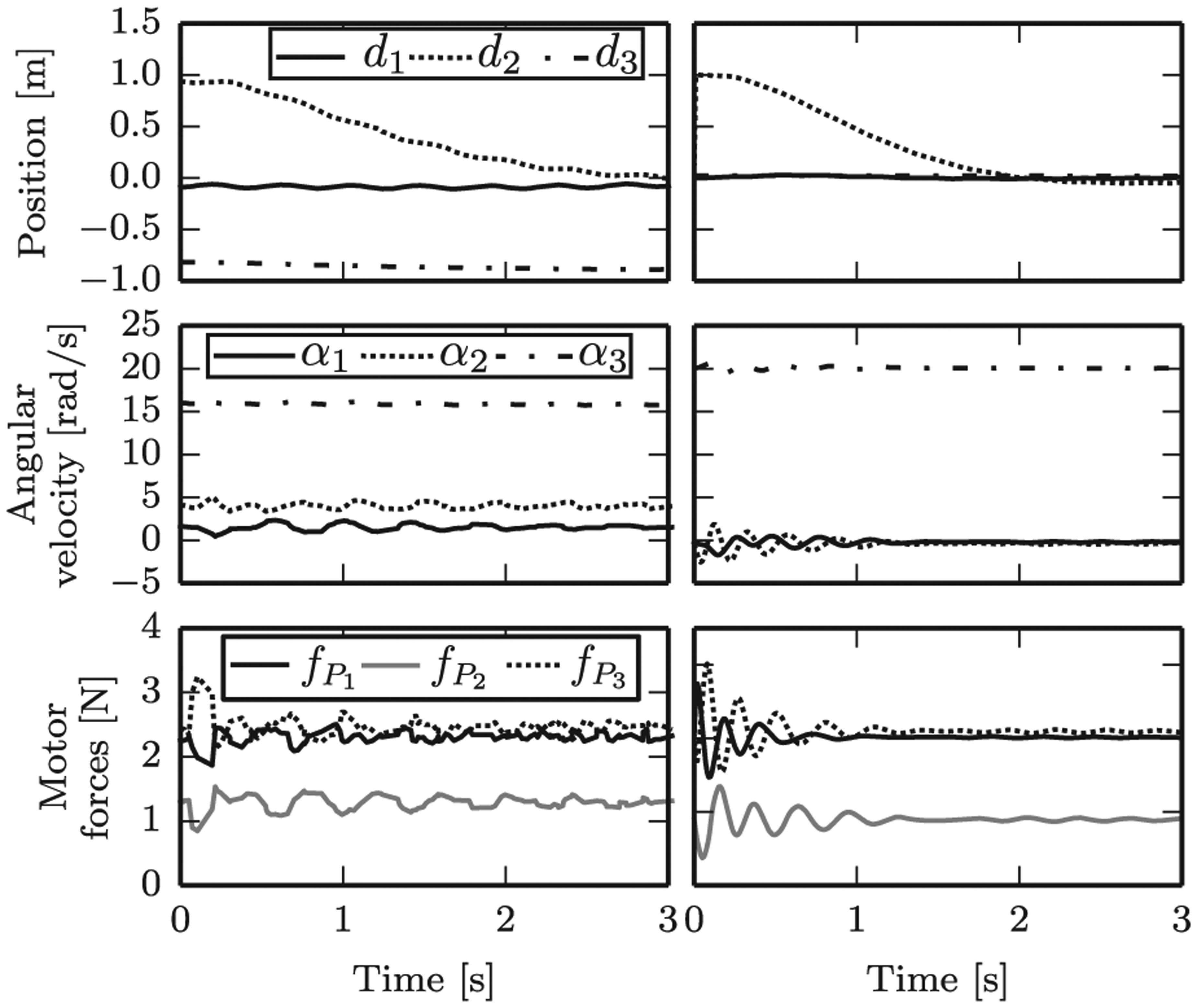
Comparison of experimental (left-hand column) and simulated (right-hand column) data for a quadrocopter with a single failed propeller, and an initial 1 m horizontal position error. The angular velocity is as expressed in the control frame C, and the position is expressed as
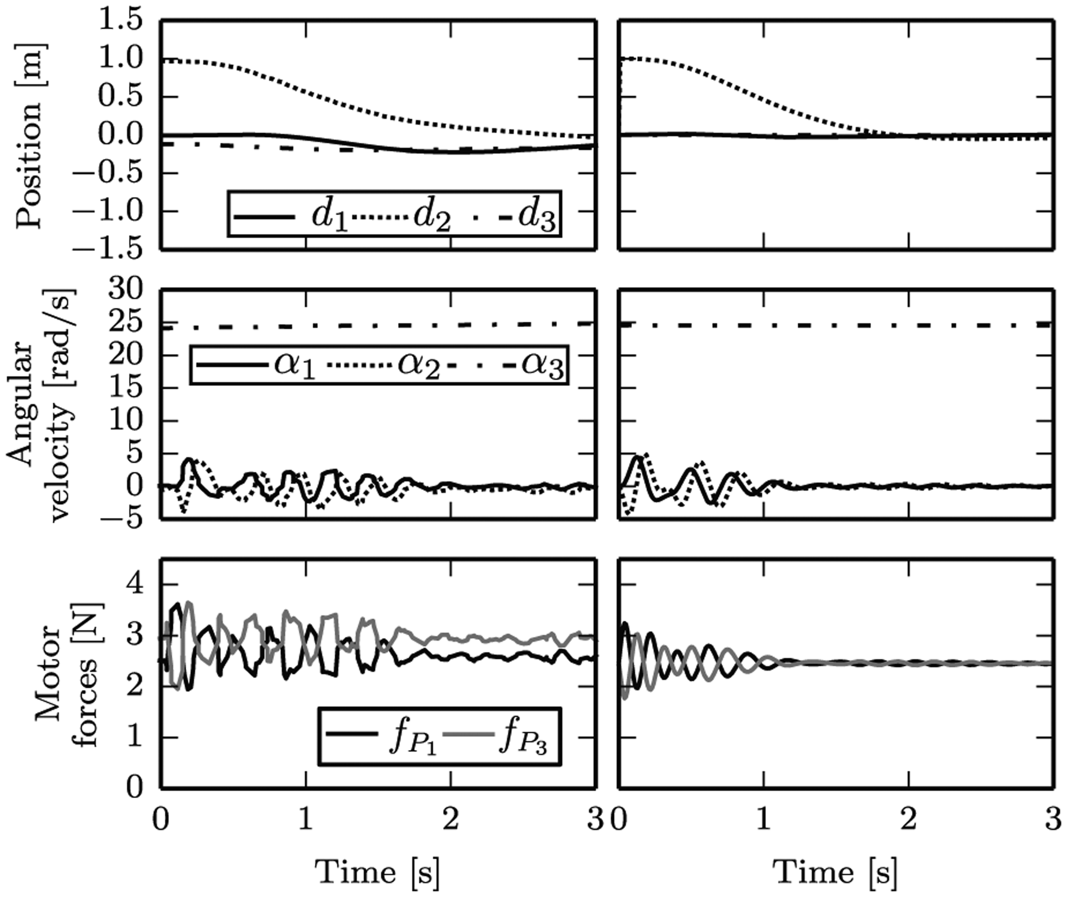
Comparison of experimental (left-hand column) and simulated (right-hand column) data for a quadrocopter with two opposing failed propellers, and an initial 1 m horizontal position error. The angular velocity is as expressed in the control frame C, and the position is expressed as
For a single failure the experimental data differs somewhat from the simulated data, most notably for the steady-state angular velocity. In experiment, the vehicle has an angular velocity component perpendicular to the
Furthermore, the vehicle has an approximately 0.8 m vertical offset in experiment for a single failure. This may be partially explained by the angular velocity offset of the experiments with respect to the simulation. In the experiment, the quadrocopter’s thrust axis is tilted farther away from gravity, and thus the feed-forward thrust to compensate for the vehicle’s weight from (20) will be too low. This could be readily compensated by, for example, adding an integral control term to the position controller, or by refining the model to allow for better prediction of the vehicle’s angular velocity equilibrium. Nonetheless, the controller successfully stabilizes the vehicle about the hover solution, and the vehicle’s horizontal error is controlled to zero as expected.
For the case of two failed opposing propellers, the simulation matches the experimental data well. It is notable that the two motors do not produce equal force in experiment after the transients have died away; this may be explained by a center of mass offset of the experimental vehicle, or an imperfection in one of the two actuators.
5.5. Special cases for controllability
Some intuition for when it is possible to control a quadrocopter that has lost one or more propellers may be gained by analyzing the hover conditions and controllability requirements of Sections 3 and 4 under some simplifying assumptions, especially for the case of losing two opposing propellers.
Specifically, it will be assumed that the vehicle’s mass moment of inertia expressed in the body frame is diagonal, with only two unique entries. The inertia of the propeller is assumed to be zero except about its axis of rotation


where, furthermore, IP,zz≪IB,zz. The propellers are assumed identical except for their handedness, so that


It is assumed that the vehicle’s angular velocity with respect to the inertial frame is much smaller than the propellers’ angular velocity with respect to the body, i.e
The vehicle’s drag torque coefficient is given below, again with only two unique entries

Defining the components of the vehicle angular velocity as
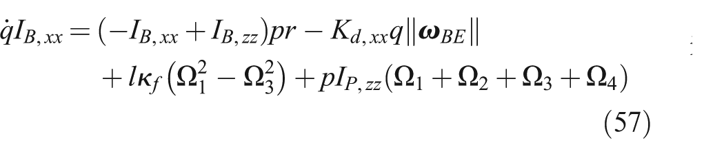
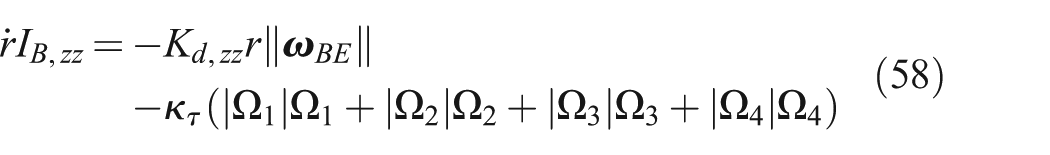
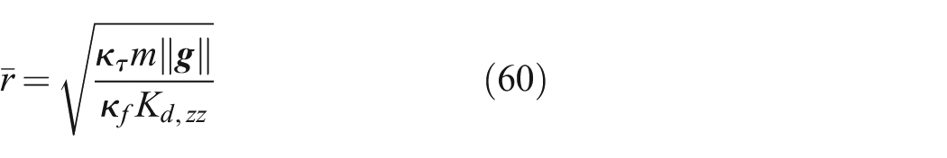
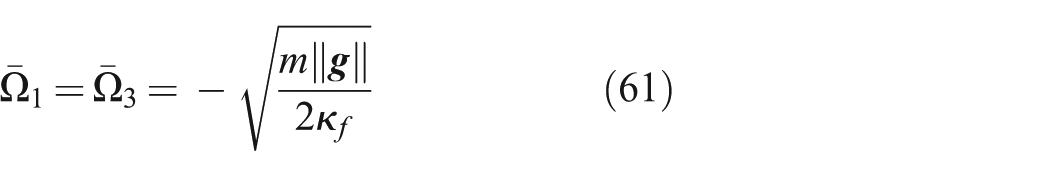
Considering specifically the loss of two opposing motors, such that Ω2 = Ω4 = 0, and constraining the hover solution so that

The attitude controllability can now be analyzed as described in Section 4, by introducing the scalar attitude input u and requiring that the total force remain constant; it follows that
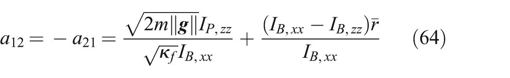

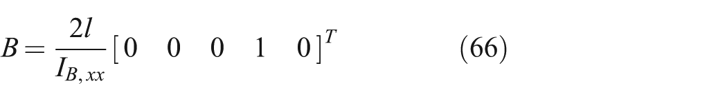
It is clear that r is an exponentially stable, uncontrollable mode of the linearized attitude system, and it will be neglected for the remainder of the analysis. A reduced, four state system remains with a single input. The controllability of this system may be determined by computing the determinant of the 4 × 4 controllability matrix of the system and ensuring that this is non-zero (Callier and Desoer, 1994).
After some tedious algebra it emerges that there are two plausible conditions where this system is uncontrollable. Firstly, if (67) holds, the cross-coupling in the attitude dynamics (3) disappears and the vehicle’s roll rate p is uncontrollable

If, instead, the following two conditions hold, the system is also uncontrollable


In this case there are two uncontrollable modes, which correspond to p + a12η1 and η2.
These two conditions may be used to determine whether a quadrocopter’s attitude will be close to uncontrollable with two opposing propellers, given its physical parameters. Unfortunately, the aerodynamic drag parameters, Kd,xx and Kd,zz, may be hard to accurately predict.
If only a single propeller has failed, the same hover solution may be selected as when two opposing propellers have failed with
Further simplifications. The preceding results may be given a more intuitive geometric interpretation by further assuming that the propellers have zero inertia, i.e. IP,zz = 0. The first case for being uncontrollable then simplifies from (67) to the requirement that IB,xx = IB,zz (recall that by assumption also IB,xx = IB,yy). This happens if the vehicle’s mass distribution is symmetric, i.e. similar to that of a sphere. The second case for being uncontrollable simplifies from (69) to IB,zz = 2IB,xx = 2IB,yy; this corresponds to the mass distribution of a two-dimensional object, e.g. a flat plate with the propellers’ thrust axes pointing along the plate’s normal.
6. Quadrocopter center of mass offsets
If a quadrocopter’s center of mass is not located at its geometric center the propeller forces will no longer all be equal when the vehicle hovers at zero angular velocity. Specifically, for the input torques of (3) to balance, propellers closer to the center of mass must produce larger forces.
For large center of mass offsets the required propeller forces may be close to (or even exceed) the propeller limits, leaving little or no control authority for feedback control. In such a situation, the approach of Sections 3 and 4 may be used to find a hover solution where the nominal motor forces are further away from the actuator limits.
As an extreme example: for a quadrocopter with propellers distributed on the corners of a square, if the center of mass is located halfway between the geometric center of the propellers and one propeller, the propeller farthest from the center of mass must produce zero force for the input torques to balance. If the center of mass moves further away from the geometric center, the far propeller must produce a negative thrust. In this situation, the vehicle will consume significantly more power than if the center of mass coincides with the geometric center. Furthermore, specific hardware may not be able to produce negative thrust.
If however the vehicle is allowed to rotate during hover, one may search, for example, for a hover solution that minimizes the required mechanical power, or maximizes the distance from the propellers’ thrust in hover to the actuator saturation limits.
As an example, consider the quadrocopter of Section 5 carrying an additional load of 0.1 kg at some distance ρ from the geometric center of the propellers. As the mass is shifted farther from the vehicle’s geometric center, the vehicle’s center of mass also moves farther from the geometric center. The ratio of vehicle mass to the additional mass implies that the center of mass is located at a distance ρ/6 from the geometric center.
The mass moment of inertia of the vehicle with the added mass may be computed using Huygen’s theorem (Zipfel, 2007). For the simplicity of analysis, it is assumed that the vehicle’s drag matrix
Figure 10 compares the motor speeds and power requirements of the quadrocopter as the mass is moved farther away from the geometric center, for both the conventional hover solution (with zero angular velocity) and the relaxed hover solution of Section 3. The mass is moved from the geometric center along the axis pointing towards propeller 1. For the conventional hover solution, the power required increases significantly as the mass is moved outwards, and at distances of ρ > 0.51 m the propeller farthest from the added mass must rotate in the direction opposite to usual.
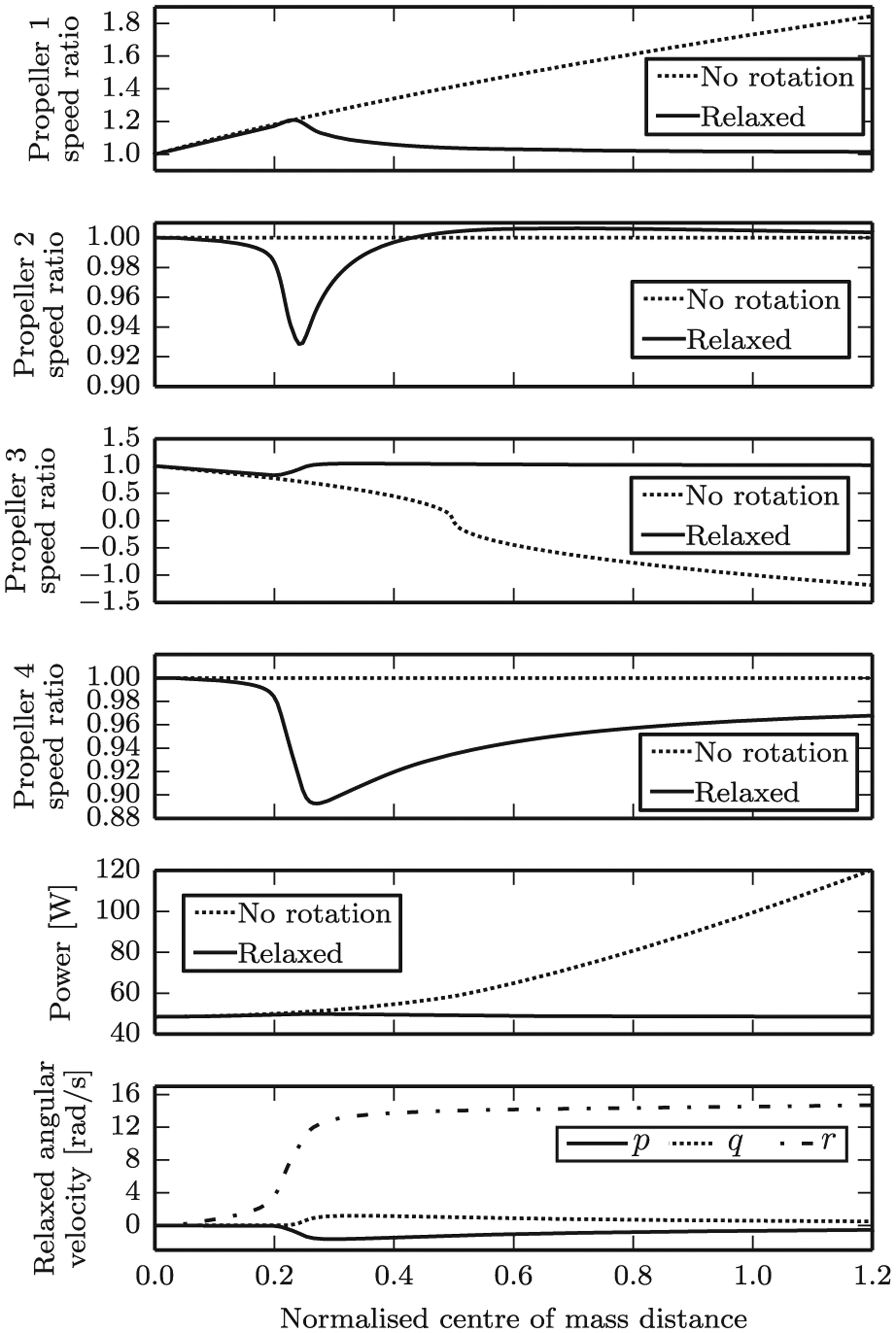
Hover solutions for a quadrocopter with an additional mass mounted at varying distances from the vehicle’s geometric center, showing the solution at which the vehicle has zero angular velocity and a relaxed hover solution of Section 3 that minimizes power consumption. Note that the abscissa is the distance of the center of mass to the geometric center, normalized by the quadrocopter’s arm length. Because of the mass ratio, the additional mass is placed six times farther from the propellers’ geometric center than the resulting center of mass. The top four graphs plot for each propeller the ratio of each required propeller speed to that speed required if the center of mass coincides with the geometric center. The bottom graph shows the three components of the vehicle’s angular velocity in the relaxed hover solution expressed in the body-fixed frame, where
The figure also shows the results if the vehicle is allowed to rotate, and a search is done to find motor speeds that minimize the mechanical power in hover. The vehicle’s mechanical power remains within 5% of the nominal power, even with displacements up to ρ = 1.2 m. The motor speeds also remain close to the nominal speeds, even at large displacements. Note that for ρ > 1.02 m the center of mass lies outside of the convex hull of the four propellers.
Thus, if the propeller’s direction of rotation is fixed, a quadrocopter may be operated under a much wider range of center of mass positions with the relaxed hover conditions compared to the restriction that the vehicle’s angular velocity is zero at hover.
7. Novel vehicles
A novel class of hover-capable vehicles may also be designed using the approach of Section 3. Here, three examples are given, with novel vehicles having two, three, or four propellers arranged symmetrically about the vehicle’s center of mass. The propellers are mounted such that their thrust axes are parallel, and all propellers have the same handedness.
This family of vehicles is dubbed “spinners,” allowing a prefix for the number of propellers. A quadspinner, trispinner, and bispinner are shown in Figure 11, and Extension 2 contains a video showing each vehicle in flight. Because of their symmetries the hover equilibria are chosen such that all propellers have the same rotational speed.
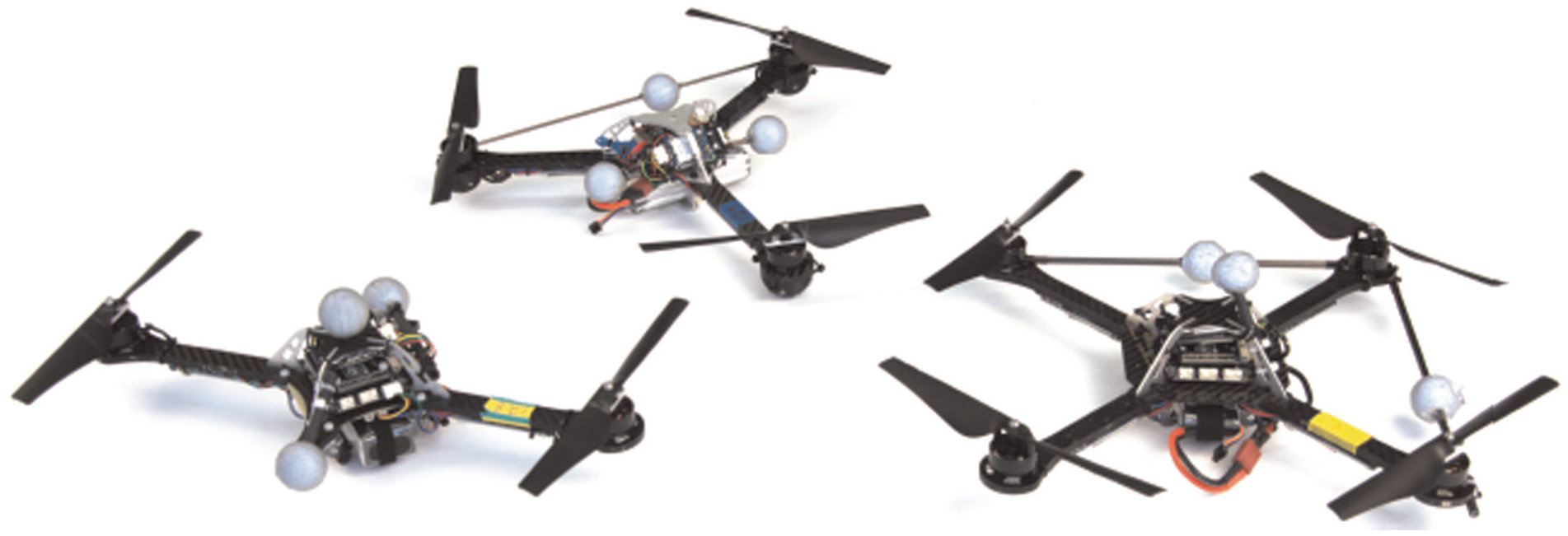
A novel class of flying vehicles, from left to right: bispinner, trispinner, and quadspinner. For each vehicle, all propellers rotate in the same direction, causing the vehicle to rotate in the opposite direction in hover. Extension 2 contains a video showing each of these vehicles flying.
Each vehicle is controlled similarly to the quadrocopter in Figure 6, where the position and attitude control are separated. A desired attitude is generated by the position controller, which makes the position behave like a second-order damped system. A LQR controller is created for the attitude, based on the first-order model of Section 4.
The notation of Section 5.2 will be used to describe the hover solutions, and again so that all entries in
7.1. Quadspinner
A normal quadrocopter may easily be converted into a quadspinner by reversing the direction of rotation of two motors (and accordingly replacing the propellers). The quadspinner shown in Figure 11 has the same physical properties as the quadrocopter presented in Section 5.1, except for the propellers’ handedness.
It will then hover at the following condition


7.2. Trispinner
A three-propeller vehicle was also created, with the propellers mounted at intervals of 120°. Conceptually, this trispinner is very similar to the quadspinner, as the propellers can produce a torque in any direction in the plane perpendicular to the thrust vector, for some given total thrust value.
Visually similar tri-rotor vehicles exist (see, for example, Salazar-Cruz et al. (2006); Zou et al. (2012)) that use a servo motor in addition to the three propellers, where the servo motor can rotate one of the vehicle’s arms and thus vector the thrust of one propeller. These vehicles can then fully control their attitudes in addition to their total thrust. The trispinner, in comparison, does not attempt to control its orientation about the thrust axis and has the advantage of being mechanically simpler.
The vehicle depicted in Figure 11 has a mass of 0.44 kg, with the propellers mounted 0.17 m from the vehicle’s center of mass. The vehicle’s inertia matrix and drag characteristics are then given below


and the hover condition is then


7.3. Bispinner
Finally, a bispinner was created, by removing two complete arms from a quadrocopter. The vehicle has a mass of 0.38 kg, and the inertia matrix and drag characteristics are as below

Note that the vehicle’s inertia about the axis connecting the motors is an order of magnitude smaller than the other terms on the diagonal. The off-diagonal terms follow as a result of the battery being positioned at an angle.
The hover condition for this vehicle is


Because of its mass distribution, this vehicle has some unique dynamic properties compared to the trispinner and quadspinner. The matrices of the linearized attitude system, computed with the method of Section 4, are as below
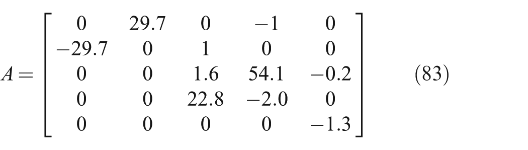

This linearized system has a single exponentially unstable mode, with eigenvalue at 35.2. This open loop instability can be clearly seen in Figure 12.
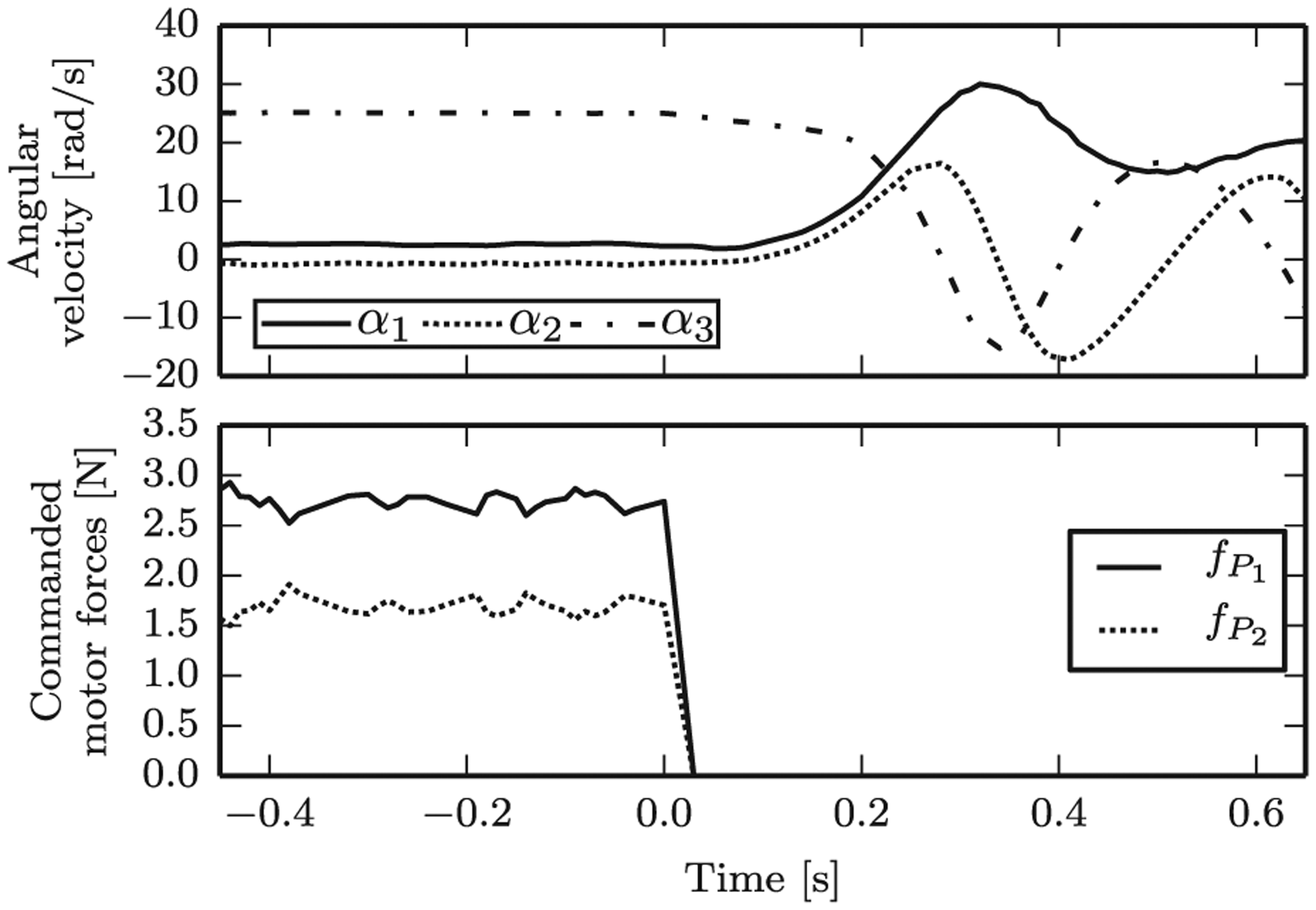
Experimental data for a bispinner at hover, where the motors (and thus attitude control) are switched off at time zero. The open loop exponential instability of the angular velocity is clearly visible, and angular accelerations up to 450 rad s−2 are measured by the vehicle’s rate gyroscopes.
8. Conclusion and outlook
This paper presents a broadened definition of hover for multicopters, where specifically the vehicle is not constrained to have zero angular velocity when hovering. The class of vehicles that can achieve these hover conditions are a superset of conventional multicopters.
By allowing a conventional multicopter to hover at non-zero angular velocity, it is shown that the vehicle can maintain controlled flight despite the complete loss of all but one propeller. This seems particularly relevant in the case of quadrocopters, as this negates one of the main arguments for using hexacopters or octocopters instead of quadrocopters. As such, the use of the proposed failsafe solutions may allow for a more widespread use (and greater public acceptance of) quadrocopters. The extended hover solutions are also shown to allow a quadrocopter to maintain flight under large center of mass disturbances.
Novel vehicles may also be conceived, such as the spinners presented herein. These vehicles could be used as novel hobbyist platforms or toys, or could be used as novel sensing platforms. For example, by mounting a line scanner to such a vehicle, and using the vehicle’s angular velocity to sweep the sensor over the environment, a mechanically simple omnidirectional sensor can be created from a line scanner.
Footnotes
Appendix: Index to Multimedia Extensions
Archives of IJRR multimedia extensions published prior to 2014 can be found at http://www.ijrr.org, after 2014 all videos are available on the IJRR YouTube channel at http://www.youtube.com/user/ijrrmultimedia
Quadrocopter failsafe flight experiments
Novel vehicles flight experiments
Acknowledgements
Funding
This research was supported by the Swiss National Science Foundation (under grant application 138112).