
Abstract
This paper develops a theoretical framework for grasping objects using customized effectors that have curved contact surfaces, and presents its application to the problem of robotic whole-arm grasping. We present a collection of immobilizing grasps and cages that can effectively restrain the mobility of a wide range of object shapes including polyhedra. Each of the grasps or cages is formed by at most three effectors with appropriate contact surfaces in contrast to customary point fingertips. We also discuss the morphology of the curved contact surfaces that can realize the grasps and cages; the surfaces can simply be planar, cylindrical, or spherical. Stable grasps are obtained by simple motion planning and control. Our theory is based on a conservative assumption that all contacts are frictionless, rigid, unilateral. Finally, we present a robotic system, comprised of a software suite and a modular reconfigurable manipulator outfitted with exchangeable end-effectors and arm links, demonstrating the theory and our approach to whole-arm grasping.
1. Introduction
This paper is concerned with developing a theoretical framework for robotic grasping using effectors (or “fingers”) with curved contact surfaces. Effectors with appropriate curvature properties can be effective for restraining the mobility of objects. For example, between the two grasps shown in Figures 1(a) and (b), each of which has one point and one planar contact, the latter shows a more restrictive grasp where the object cannot actually escape from the effectors due to the concavity of the effector surface contacting the vertex. We also present one application of the idea to a scenario of whole-arm grasping objects, implemented on a modular robot system with exchangeable end-effectors and arm links. Figure 1(c) shows a grasp by the modular manipulator outfitted with two end-effectors that have curved contact surfaces.
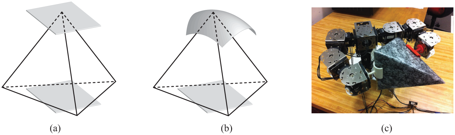
The tetrahedron is grasped by (a) the two planar effectors, (b) the planar and concave effectors, and (c) the modular manipulator.
It has been customary to employ the abstraction of point fingers in developing theories for robotic grasping and caging (see Section 2); this approach has the advantage of generality, but there are challenges in, for example, designing a physical system providing a sufficient number of independently controlled fingers that can realize the theories. Indeed, most practical solutions in autonomous grasping involve specially designed hardware and control algorithms that are tailored only to a couple of objects to be handled or grasped. A robotic system that can grasp a wide variety of object shapes without many different types of effectors or complex multi-fingered hands can save time and cost in a wide range of scenarios, from handling material in a warehouse to clearing rubble in an unstructured environment. In addition, it is imperative to develop planning algorithms that can guarantee the stability of the process of grasp acquisition and robustness to inevitable sensing/positioning errors; however, the complexity in modeling compliance or friction accurately is one of the challenges that make it hard to develop such algorithms.
We present a novel theory of three types of immobilizing grasps and cages that can effectively restrain the mobility of any object modeled as a polyhedron. The grasps and cages are formed by at most three effectors with curved contact surfaces, which can simply be a planar, cylindrical, or spherical one. The cages allow us to obtain stable grasps by simple motion planning and control in a manner robust to errors and uncertainties. In addition, the theory is extended with more types of grasps and cages. We apply the theory to developing hardware and software for stable, robust object grasping with a modular robot system, which can adapt to the sizes and shapes of a wide variety of objects. Our work is based on a conservative assumption that two bodies in contact can only push each other (unilateral contact) and there is neither friction nor compliance in contact.
This paper is organized as follows. In the following section, we review the relevant literature in the areas of robotic grasping and caging. Section 3 introduces some concepts and terminology necessary to develop our theory and algorithms. Section 4 discusses three types of immobilizing grasps using effectors with curved contact surfaces that can be applied to a wide range of object shapes including polyhedra. Section 5 discusses three types of cages derived from the immobilizing grasps and explains how to establish sufficient conditions for caging. Section 6 presents an algorithm for synthesizing the immobilizing grasps and cages. Section 7 presents one application of our theory to whole-arm grasping with implementation on a modular robot system. We conclude in Section 8, with suggestions for future work. In the Appendix, we extend our theory by adding more types of three- and two-dimensional grasps and cages.
2. Related work
Robotic grasping has been an active research area over the past few decades; see Bicchi and Kumar (2000) for a general survey. Section 2.1 outlines the literature focusing on immobilizing objects with multiple contacts. Section 2.2 introduces prior work on caging objects. Section 2.3 reviews modular robotic approaches to manipulation tasks. This paper builds on our earlier work presented in Seo et al. (2013).
2.1. Prehensile approach
We begin by discussing the closure properties of grasps. A grasp is defined as force closed (Nguyen, 1988) if and only if it can resist any external wrench. If a grasp is force closed with frictionless contacts, it is said to be form closed (Lakshminarayana, 1978) or immobilized (Rimon and Burdick, 1998a). Trinkle (1992) proposed a quantitative test formulated as a linear program for detecting form closure. Markenscoff et al. (1990) showed that it is possible to immobilize a three-dimensional object with seven frictionless point contacts, using first-order theories based on contact normals. Algorithms for synthesizing force or form closed grasps have been presented by Borst et al. (1999), Ponce et al. (1997) and van der Stappen et al. (1999). Rimon and Burdick (1998a, 1998b) developed a second-order mobility theory for rigid bodies in contact where the curvature properties at the contacts are taken into account. Czyzowicz et al. (1991) showed that
It has been discovered that the stability of a grasp depends on the geometry of the grasp, contact forces, and material properties. Mason and Salisbury (1985) established a framework for testing the stability of a grasp: a grasp is stable if its stiffness matrix is positive definite. Cutkosky and Kao (1989) showed that grasp stability is a function of local geometry, fingertip models, and the compliance of the fingers. Nguyen (1989) proved that all force-closed grasps can be made stable. Howard and Kumar (1996) established a framework for analyzing grasp stability that takes compliance, contact forces, and the local curvature properties of the bodies in contact into account. It was shown that immobilization implies dynamic stability with elastic contacts (Rimon and Burdick, 1998a; 1998b).
In practice, having a large number of contacts can be beneficial to grasp stability; however, synthesizing such a grasp can be computationally intractable. Pollard (2004) presented an efficient algorithm for synthesizing manycontact grasps based on user-provided examples. Similar approaches can also be seen in the literature on whole-body grasping (Hsiao and Lozano-Perez, 2006) and enveloping grasping (Trinkle et al., 1988). Napier (1956) showed that there are two approaches to achieving stability in human grasping: power grip and precision grip. Whole-body grasps and enveloping grasps are in the same vein as the human power grip, where an object is held by a large number of contacts between the flexed fingers and the palm.
Since Hanafusa et al. (1977) presented one of the earliest examples of robotic hands, various robotic hands have been developed. Our work is relevant to the approach of building simple yet versatile end-effectors that can be seen in Dollar and Howe (2010), Jacobsen et al. (1986), Kragten et al. (2011), Mason et al. (2012) and Ulrich et al. (1988). Another relevant approach can also be seen in the literature on modular fixturing (Brost and Goldberg, 1996; Ponce, 1996). Recently, there has been growing interest in developing robotic systems that can grasp/manipulate objects with some autonomy. Saxena et al. (2008) presented a vision-based approach to robotic grasping and demonstrated real systems that can grasp previously unknown objects using two-dimensional images; similar approaches can be seen in Bowers and Lumia (2003) and Morales et al. (2002). Hudson et al. (2012) developed an autonomy system that can perform dexterous, high-precision tasks such as key insertion.
2.2. Non-prehensile approach
In contrast to the prehensile approach, the literature on caging investigates how to arrange “obstacles” (that is, robotic fingers or effectors) around an object so as to bound its mobility without necessarily making contact. Caging allows us to sidestep some difficult issues such as modeling contacts or optimizing contact forces although the caged object may have some freedom to move. Rimon and Blake (1999) formulated a technique for computing the cages of two-fingered hands; Davidson and Blake (1998a) extended their result to three-fingered hands. Vahedi and van der Stappen (2008a, 2008b, 2008c, 2009) provided an algorithm for synthesizing cages of two and three fingers around polygonal objects and formalized the concepts of squeezing and stretching cages for polygonal objects, which were generalized by Rodriguez and Mason (2009) to address objects in Euclidean spaces of arbitrary dimension. Allen et al. (2012) presented a simpler algorithm for computing two-fingered cages for polygons based on contact space analysis. Wan et al. (2012) proposed a solution to synthesizing three-fingered cages on the plane where two of the fingers are fixed. Fruchard (2012), Maehara (2011) and Zamfirescu (1995) investigated how to cage objects with a single circle. Rodriguez et al. (2012) discussed the relationship between caging and grasping: they investigated when a cage can be a useful waypoint to an equilibrium grasp.
Recently, there have been efforts to take advantage of caging to make robotic grasping tasks robust. Davidson and Blake (1998b) presented error-tolerant, vision-based planar grasping by closing the fingers that form a cage. Gopalakrishnan and Goldberg (2002) presented a simple gripper with two vertical, parallel cylindrical jaws that can stably grasp objects by forming a cage on concavities. Diankov et al. (2008) proposed a motion-planning algorithm for performing manipulation tasks with cages, relaxing task constraints. Yokoi et al. (2009) presented an approach to transporting objects using cages formed by not only robots, but also the environment such as the walls. Cappelleri et al. (2011a, 2011b) employed cages formed by micro-manipulators for transporting and manipulating micro-scale polygonal parts. Dogar and Srinivasa (2011) showed that simple manipulation such as quasi-static pushing can help robots stably cage and grasp objects, even in clutter. There is a body of literature featuring decentralized approaches to caging; we refer the reader to Section 2.3.
2.3. Modular approach to robotic manipulation
The literature on multi-robot manipulation provides techniques for handling objects in a cooperative manner. When multiple robots manipulate a common object, it is necessary to control both the motion of the object and the internal forces exerted on the object (Murray et al., 1994). In addition, the dynamics of such systems are typically subject to unilateral constraints: the robots can only push or pull (for example, by cable tension) the object. Bernard et al. (2011), Cheng et al. (2009), Fink et al. (2011), Murray (1996), Sreenath and Kumar (2013) and Sugar and Kumar (1999) provided solutions to the problem with application to ground or aerial transport. The literature shows that robotic object handling can be facilitated by caging with a team of multiple robots: Fink et al. (2008), Kosuge et al. (1999), Montemayor and Wen (2005) and Pereira et al. (2004) presented approaches to developing decentralized control algorithms. Some of the literature on cooperative transport took inspiration from the behavior of social insect colonies (Berman et al., 2011; Kube and Bonabeau, 2000).
3. Preliminaries: Caging and grasping
This section introduces some concepts and terminology related to the caging and grasping that we use in developing our theory and algorithms.
3.1. Caging
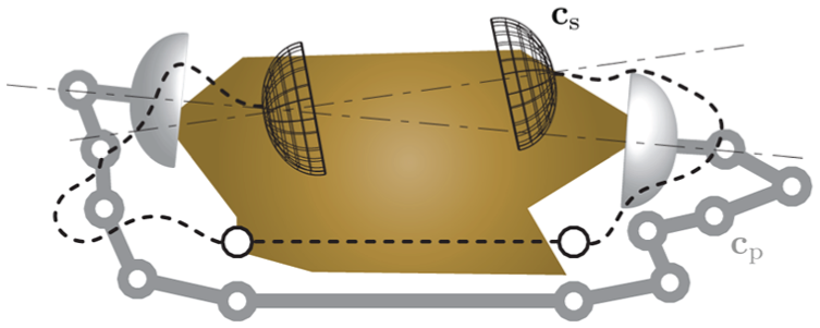
A cage around an object bounds its mobility (Figure 2(a)): the caged object cannot be moved arbitrarily far from its original position without penetrating the surrounding effectors forming the cage. Equivalently, a cage can also be defined in terms of the mobility of the surrounding effectors by regarding the object as an obstacle: according to Rodriguez et al. (2012), a cage is a configuration of effectors that lies in a compact, connected component of the free space (LaValle, 2006) of the system of the effectors (note that the system is assumed to move as a single rigid body).
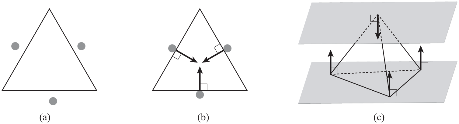
(a) Caging a triangle with three point effectors. (b) Immobilizing the regular triangle with the three point effectors located at the center of each edge. (c) Clamping the tetrahedron with the two planar effectors contacting the vertex–face pair. In (b) and (c) the arrows are involved unit contact wrenches under the assumption of frictionless, rigid, unilateral contact.
Rodriguez et al. (2012) formalized the concept of an F-cage, which is generally stricter than that of a cage. Let F be a scalar function defined on effector configurations. Then an F-cage is a configuration of the effectors that cage an object, even if they have freedom to move while maintaining the value of F. An F-cage is an F-squeezing (stretching) cage if it still cages the object even if the effectors have freedom to move while decreasing (increasing) the value of F.
3.2. Contact
In this work, we are mainly concerned with an object modeled as a polyhedron in contact with effector surfaces. There can then be three types of contact geometry: point, line, and planar contact (Mason, 2001; Mason and Salisbury, 1985). For example, Figure 2(c) shows one point and one planar contact between the two planar effector surfaces and the object. A contact can apply a contact wrench (Mason, 2001; Murray et al., 1994), a contact force/moment pair, given by the positive linear combinations of unit contact wrenches, which are normalized, linearly independent vectors that span the vector space of the contact wrenches (see Figures 2(b) and (c)). Our work is based on an ideal yet conservative assumption that all contacts are frictionless, rigid, unilateral (unilateral contacts can only push an object); then, the unit contact wrenches are the vectors of the normalized screw coordinates only of the inward-pointing contact normals (Mason, 2001). If we assumed more realistic, yet capable (for example, frictional, soft, or bilateral) contacts, more types of unit contact wrenches should be considered (Murray et al., 1994); this shows the conservativeness of our assumption.
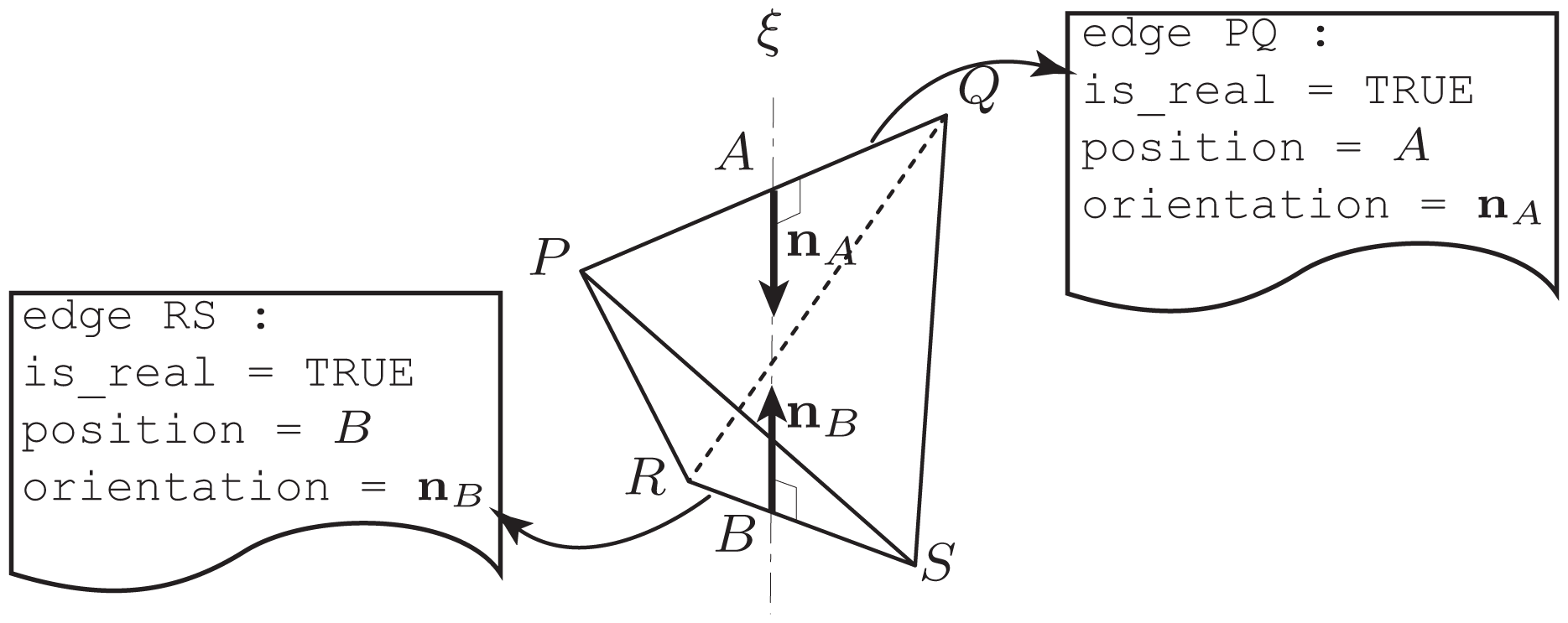
A line contact can be made on a virtual edge (Peshkin and Sanderson, 1986), which is composed only of the vertices delimiting the edge without the interior (Figure 3). It can be seen that a “real” edge and a virtual edge are indistinguishable in terms of their ability to produce contact wrenches under the assumption of frictionless, rigid, unilateral contact if we are given a sufficiently large effector surface that can contact all the delimiting vertices: in Figure 3, even if the virtual edge were real (like edge
The plane is contacting the virtual edge
3.3. Grasping
To grasp an object is to restrain its mobility by making contacts with effectors. A grasp can be in equilibrium if the net contact wrench, the sum of all contact wrenches, can be made zero in such a way that not all contact wrenches are equal to zero (Rimon and Burdick, 1998a). If there is no object twist, a linear/angular velocity pair (Murray et al., 1994), consistent with the contacts of an equilibrium grasp, the object is said to be immobilized to the first order (Rimon and Burdick, 1998a) (or form-closed (Mason, 2001)), that is, the configuration of the object is an isolated point in the free space. Even if such a twist exists, any finite motion may be restricted by considering surface curvature effects. For example, in Figure 2(b), the object may instantaneously rotate about its centroid (so a first-order kinematic analysis does not predict immobility), but any finite rotation results in penetrating the effectors. This idea is formalized using the concept of second-order immobility presented by Rimon and Burdick (1998a, 1998b); they discovered that second-order immobility suffices for not only complete immobility, which means that the configuration of the grasped object is isolated from the free space, but also local, dynamic, asymptotical stability of the grasped object. Seven (four) point effectors are required to immobilize a polyhedral object to the first (second) order with frictionless, rigid, unilateral contacts (Czyzowicz et al., 1991; Markenscoff et al., 1990). Such immobility conditions are purely geometric; information on contact geometry is thus sufficient to investigate first- or second-order immobility. The immobilizing grasps we will present also exploit surface curvature effects as second-order immobility. An equilibrium grasp is called a grasping cage (Rodriguez et al., 2012) if it can also cage the object; a grasping cage is not necessarily an immobilizing grasp.
3.4. Clamping
Clamping (Bose et al., 1996), also known as parallel-jaw grasping, is one way to realize equilibrium grasps by holding an object between two parallel planar “jaws”. An object that is clamped can only move on the plane of the jaws, without penetrating them. If the jaws can exert frictional forces, the grasp can be force closed: an arbitrary contact wrench can be applied. Consider the antipodal pair of a convex polyhedral object, which is the intersection of the object with a pair of parallel support planes; an antipodal pair can thus be a vertex–vertex, vertex–edge, vertex–face, edge–edge, edge–face, or face–face pair. According to Bose et al. (1996), all convex polyhedra can be clamped with parallel-jaw grippers. The grippers are then on one of the last four types of antipodal pairs, that is, vertex–face, edge–edge, edge–face, or face–face; such an element pair can determine the width of a polyhedron, the minimum distance between two parallel supporting planes. Figure 2(c) shows a clamp on a vertex–face pair.
4. Immobilizing objects using effectors with curved contact surfaces
Here, we discuss how to immobilize a three-dimensional object using at most three contacts, each of which can be a point, line, or planar contact made by an effector with a curved contact surface that can be represented as a two-dimensional manifold with a boundary. In Sections 4.1, 4.2, and 4.3, we present three types of immobilizing grasps that can be applied to objects modeled as polyhedra; we also discuss the geometry of effector surfaces that can realize the grasps. In Section 4.4, we show that any polyhedron can be immobilized by the grasps and discuss how the assumption of polyhedral objects can be relaxed.
4.1. Immobilizing with three point contacts
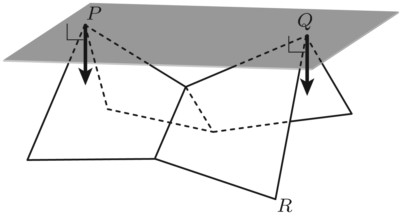
Here we show that it is possible to immobilize a polyhedron with three point contacts. We begin by choosing three vertices where the contacts can be made. See Figure 4(a). Let P and Q be two vertices of the given polyhedron where two point contacts can be made with a pair of parallel planes perpendicular to
(a)
Three point contacts on P, Q, and R made by curved effector surfaces can immobilize the polyhedron if: (1) a neighborhood of the effector surface around the point contacting P (Q), except for the point itself, can be embedded inside the ball whose diameter has end-points P and Q (Figure 4(b)); and (2) a neighborhood of the effector surface around the point contacting R, except for the point itself, can be embedded inside the cylinder of radius
4.2. Immobilizing with a point, a line, and a planar contact
Here we show that it is possible to immobilize a polyhedron with one point, one line, and one planar contact. We begin by choosing a vertex, an edge, and a face where the contacts can be made. See Figure 5(a). At P and □QRST, a point and a planar contact can be made with a pair of parallel planes. The ray of the inward-pointing contact normal at the vertex intersects the interior of the face; the inward-pointing contact normals at the face point toward the vertex. Among the edges incident to P, choose the one with the least slope with respect to the face, that is,
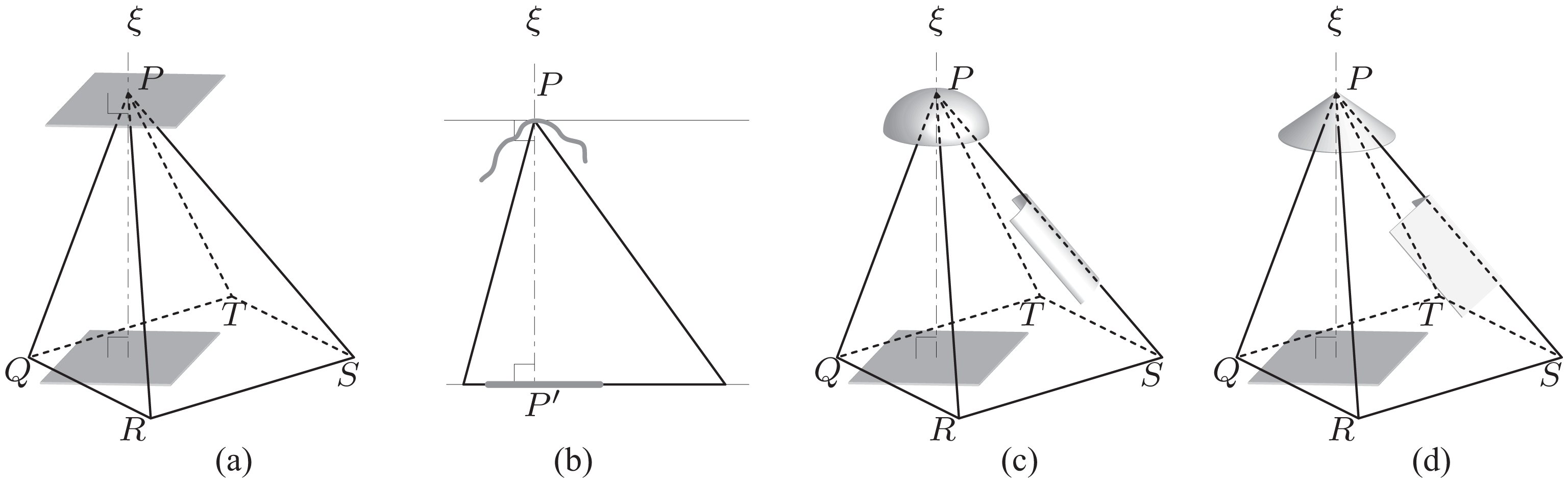
(a)(P,
Three (one point, one line, and one planar) contacts on the vertex (P), edge (
4.3. Immobilizing with two line contacts
Here we show that it is possible to immobilize a polyhedron with two line contacts. We begin by choosing two edges where the contacts can be made. See Figure 6(a).
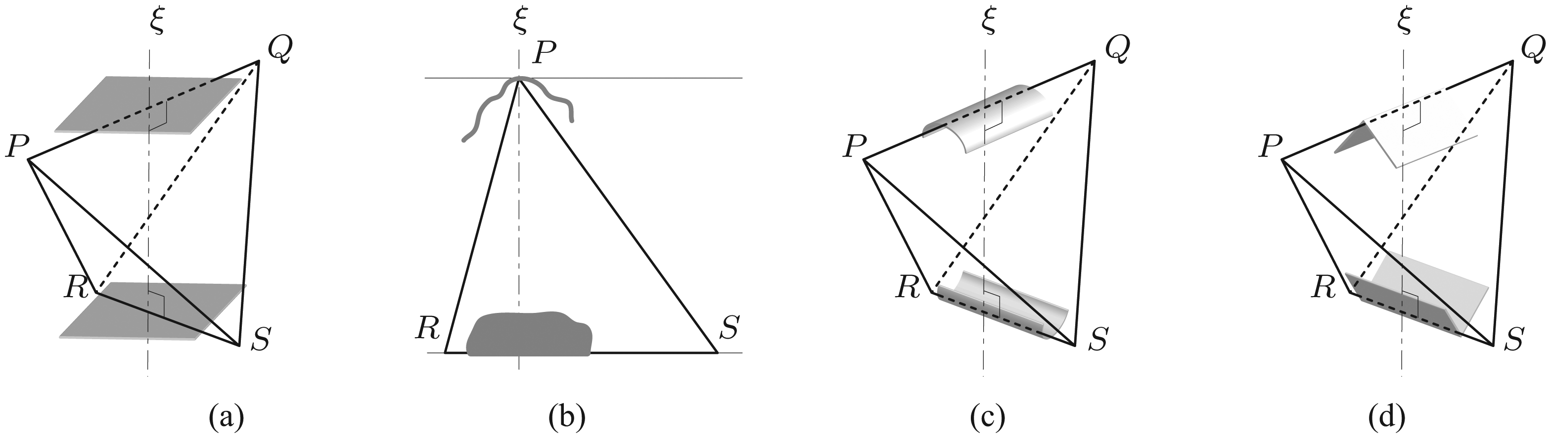
(a)
Two line contacts on the edges by curved effector surfaces can immobilize the polyhedron if a neighborhood of the effector surface around the line segment contacting
4.4. Analysis
The three types of grasps discussed in Sections 4.1, 4.2, and 4.3 are complete: every polyhedron can be immobilized by applying at least one of the grasps. We break the analysis into two theorems.
First, we show that the grasp of three point contacts discussed in Section 4.1 suffices to immobilize all polyhedra.
Proof. Every polyhedron has a vertex–vertex pair
Next, we can find an additional vertex, not on
Constructively, as explained in Section 4.1, we get immobility with three appropriately curved effector surfaces respectively contacting P, Q, and R. Note that P, Q, and R are on the convex hull of the polyhedron; otherwise, P and Q do not determine the maximum distance and R is not the most distant from
We now show that the other two types of grasps discussed in Sections 4.2 and 4.3 are also complete in the sense that every polyhedron whose vertices are in general position, not admitting any pair of either two planes or a line and a plane that are parallel, can be immobilized by at least one of those grasps.
Proof. Consider the convex hull of the given polyhedron. Because the convex hull does not have any pair of either two faces or an edge and a face that are parallel, it can be clamped at one of its antipodal vertex–face or edge–edge pairs. The convex hull (and thus the original polyhedron) can then be immobilized using the pair by applying the grasp discussed in Sections 4.2 or 4.3.
Note that the grasps employed in Theorem 2 might have contacts on virtual edges or faces that are on the convex hull but are not real elements of the original polyhedron.
In the Appendix, more types of two- and three-dimensional immobilizing grasps are presented, in addition to the collection of the complete grasps.
5. Caging objects using effectors with curved contact surfaces
Based on the three types of immobilizing grasps discussed in Section 4, it can be seen that every polyhedron can be caged by two effectors.
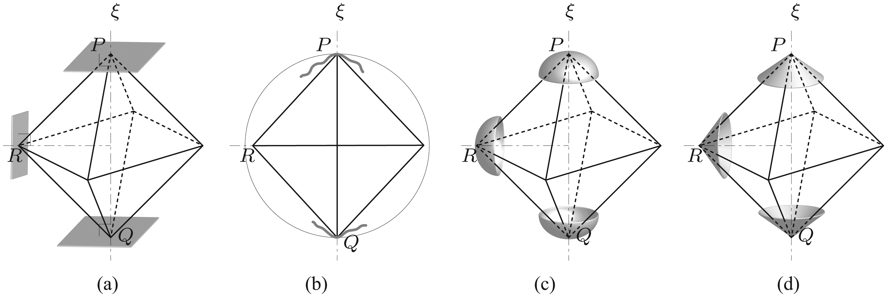
Proof. According to Sections 4.1, 4.2, or 4.3, it is possible to cage a polyhedron with two curved effector surfaces making contacts at a vertex–vertex, vertex–face, or edge–edge pair. For example, Figure 7 shows three types of cages obtained by the two effectors at the antipodal pairs in Figures 4(c), 5(c), and 6(c), respectively. According to Theorems 1 and 2, every polyhedron can be caged by at least one of the three types of cages.
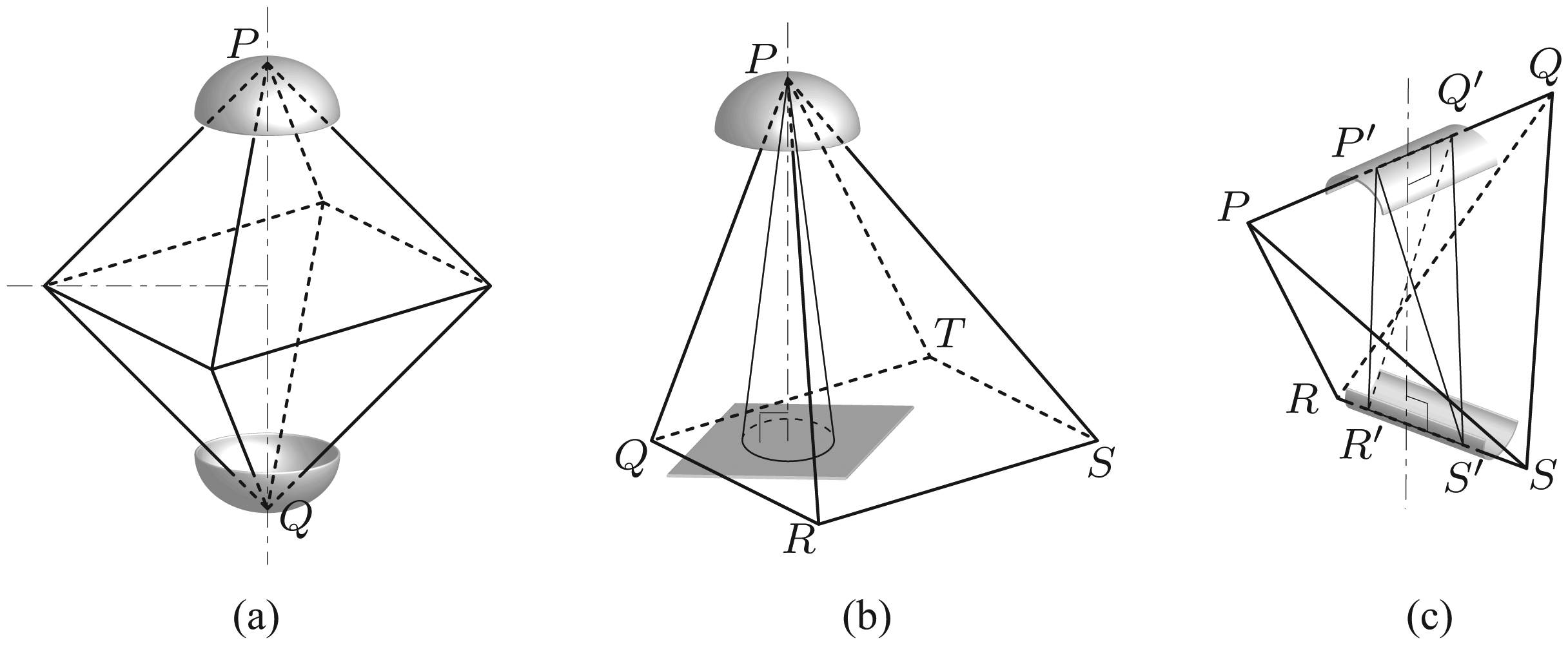
Cages of two effectors with curved contact surfaces. The inscribed shapes (the right circular cone in (b) and the tetrahedron
Although the effectors are contacting the objects in Figure 7, a cage does not necessarily have to make contacts with the object. In order to see if an object is caged, it is necessary to take the overall effector geometry into account because it is required to verify the compactness of the component of the free space to which the configuration of the object belongs, which is a non-local property. For example, the distance between effectors is critical in our discussion on caging here. In contrast, recall that we need only local curvature properties in establishing the immobilizing grasps in Section 4.
In this section, we address how to establish sufficient conditions for caging three-dimensional objects in analytical (Section 5.1) and empirical (Section 5.2) manners. In Section 5.3, we present a theoretical analysis on how to acquire stable grasps from the cages and discuss how our assumption of polyhedral objects can be relaxed.
5.1. Analytical method
Here we present three types of cages that are derived from the three types of immobilizing grasps. Considering a simpler object geometry that can be inscribed in the original shape, we discuss how to establish sufficient conditions for caging in an analytical manner.
5.1.1. Caging on a vertex–vertex pair
Consider a vertex–vertex pair of a given polyhedron such as
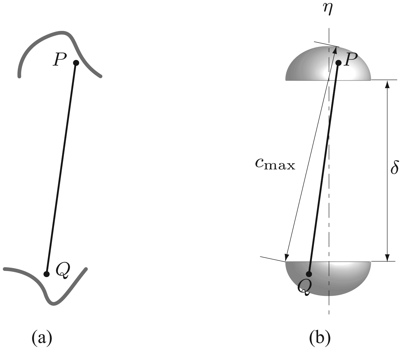
(a) The planar view shows vertices P and Q contained in the curved effectors. (b) A cage of two hemispherical effectors.
Consider two curved effectors that can contain the vertices, as shown in Figure 8(a). If the maximum clearance between the effectors is less than
5.1.2. Caging on a vertex–face pair
Consider a vertex–face pair of a given polyhedron such as (P, □QRST) in Figure 7(b), allowing us to establish the immobilizing grasp discussed in Section 4.2. Here we investigate how to cage a right circular cone that can be inscribed in the convex hull of the vertex and face (see the right circular cone with apex P in Figure 7(b)).
First, suppose that two infinitely large planar effectors are clamping the right circular cone at the apex and base. We now allow the effectors to move in such a way that they remain parallel to each other (Figure 9(a)). If their distance
(a) The planar view shows the right circular cone in Figure 7(b) is contained between the two parallel planar effectors. (b) The curved and planar effectors are caging the cone. (c) A cage of the hemispherical and planar effectors. The hemispherical effector is only allowed to translate along its axis
5.1.3. Caging on an edge–edge pair
Consider an edge–edge pair of a given a polyhedron such as
First, suppose that two infinitely large planar effectors are clamping the tetrahedron
(a) The planar view shows tetrahedron
5.2. Empirical method
Sufficient conditions for caging can also be established in an empirical manner by making use of off-the-shelf motion-planning algorithms, particularly when the effector geometry is analytically challenging. We here employed a sampling-based motion planner implementing an RRT-based algorithm, available in ROS;
1
our approach is in the same vein of using sampling-based path planning for (dis)assembly planning (Ferre and Laumond, 2004; Le et al., 2009; Sundaram et al., 2001). In the experiment below, changing the distance between two effectors at intervals of 1 cm, we see if the motion planner can find paths for an object between the two effectors to reach random target configurations sufficiently far from the effectors; for each query distance, denoted by
First, we consider a scenario where two torus-shaped effectors are caging an object on a vertex–vertex pair. Figure 11(a) shows how we set up experiments with the cone-like object. The effectors are only allowed to translate along
Establishing cages in an empirical manner. (a) and (b) Caging on a vertex–vertex pair. (c) and (d) Caging on a vertex–face pair. (e) and (f) Caging on an edge–edge pair.
Second, we consider a scenario where a torus-shaped and a planar effector are caging an object on a vertex–face pair. Figure 11(c) shows our experimental setup with the cone object: the square-shaped planar effector is contacting the base of the cone; the torus-shaped effector is allowed to translate along
Third, we consider a scenario where two open-ended, half-cylindrical effectors are caging an object on an edge–edge pair. In the experimental setup shown in Figure 11(e), the effectors are only allowed to translate along
In the trials above, the sampling-based motion planner did not have to try to take samples on a lower dimensional manifold of the configuration space, which can be hard because such manifolds have measure zero, since our intention was to see how far the two effectors can be separated from each other while still caging the object.
5.3. Analysis
The sufficiency of our caging conditions allows us to address errors/uncertainties in not only fabricating the effectors but also sensing and control relating to grasp acquisition. We now discuss how to get a grasping cage (recall Section 3.3) from any of the cages discussed so far. We also discuss how to relax the assumption of polyhedral objects.
Proof. We first show that
In addition, the cages are
Rodriguez et al. (2012) discovered that the role of grasping functions in grasping is analogous to that of Lyapunov functions in stability analysis. Specifically, Theorem 3 shows that an object caged by any of our cages can be stabilized by simply moving the effectors closer to each other by relative translation. A translation that monotonically decreases
6. Synthesizing grasps and cages
In this section, we present an algorithm for finding element pairs/triples for the immobilizing grasps and cages discussed in the previous sections. Our pseudocode is presented in Algorithm 1. Given the model of an object, the output of the algorithm specifies where to place effectors in order to obtain the immobilizing grasps/cages. The following paragraphs elaborate each line of the algorithm.
The label for the edge–edge pair,
Figure 13(a) shows an example object; Figures 13(b), (c), and (d) show some element pairs found by running the algorithm. The convex hull of the rock model has 162 vertices, 480 edges, and 320 faces; it took 0.02 s to find 21 vertex–vertex, 9 vertex–face, and 18 edge–edge pairs with our C++ implementation running on a 2.53 GHz/4 GB machine. The vertex–vertex and vertex–face pairs (Figures 13(b) and (c)) can be augmented into the element triples for immobilizing grasps as explained in Line 2.
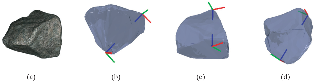
(a) A polyhedral rock model with 1000 faces (courtesy of Malcolm Lambert, Intresto Pty Ltd). (b), (c), and (d) respectively show a vertex–vertex pair, a vertex–face pair, and an edge–edge pair found by running our algorithm. The reference frames are positioned and oriented such that the origin is at the contact position and the z-axis is along the contact normal, according to the label of each element pair.
A given object model can be immobilized by making contacts with any of the resultant element pairs or triples: we contact target elements with curved effector surfaces, whose curvature is sufficiently large, positioned and oriented as the label specifies. For caging purposes, we do not have to search for the third element in Line 2. Furthermore, effectors do not necessarily have to be controlled to make contacts with their target elements: the target positions for a pair of effectors caging an object can be moved away from the positions specified in the label as long as their distance
Because all the elements found by Algorithm 1 (possibly except for the edge of a vertex–edge–face triple) are on the convex hull, that is, the outer frontier of the object, some of them can be virtual. An effector for a virtual edge or face should be large enough to contact all the vertices delimiting the virtual element. If it were not for an effector with a sufficiently large surface for a given virtual element, we would instead need to make contact with a smaller real element in the interior of the convex hull. Then, we may forgo computing the convex hull and proceed with the original mesh although it can take more time and the returned elements may be less easy to access in the case that they are in the interior of the convex hull.
7. Whole-arm grasping using end-effectors with curved contact surfaces
In this section, we address how our theory can be applied to a scenario where two collaborating manipulator arms, which may be the arm–torso chain of a humanoid robot or two collaborating industrial robot arms, are grasping objects using end-effectors with curved contact surfaces. The stability of the two-effector cages discussed in Section 5 allows us to add more contacts not necessarily from the end-effectors; the scenario may then be called whole-arm grasping, as can be seen in Figure 14. Whole-arm grasping can be particularly effective for grasping large, bulky objects such as rocks, with relatively small end-effectors. Without fabricating dedicated end-effectors, the curved shapes may be emulated in some way, for example, cupping the fingers of a multi-fingered end-effector. Section 7.1 presents our algorithm for whole-arm grasping. Section 7.2 discusses the implementation of whole-arm grasping on a modular robot system. Section 7.3 presents a set of experiments.
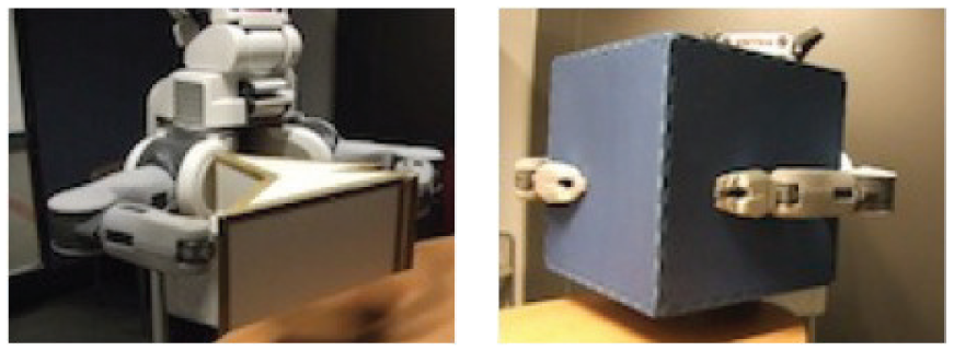
Two planar whole-arm grasps by the PR2. The robot is grasping the prismatic objects using the entire arm chain.
7.1. Approach and algorithm
Our approach to whole-arm grasping is composed of two phases: pre-shaping and squeezing. In the pre-shaping phase, a robot cages an object using its two end-effectors with curved contact surfaces as discussed in Section 5. In the squeezing phase, the robot performs a squeezing motion for the end-effectors. During the squeezing motion, not only the end-effectors but also other links can be made to contact the object without adversely affecting the stability of the object if we assume that the robot is position-controlled without compliance, in addition to the assumption of frictionless, rigid, unilateral contact.
Proof. The same argument as the proof of Theorem 3 can also be applied here by regarding: (1)
The corollary shows that as long as the end-effectors are squeezing, the final state is guaranteed to be a stable equilibrium grasp that can be composed of contacts from the whole body of the robot. Our approach can facilitate planning and control for grasping: in the pre-shaping phase, the robot can aim at any of the cages, whose collection is not a set of measure zero in the configuration space; the squeezing phase can be performed in a blind manner, only by position-control, without direct feedback of the object pose. In fact, the two-phase approach has some similarities with multi-fingered grasping (Miller et al., 2003): approaching an object followed by “closing” the hand.
Our pseudocode is presented in Algorithm 2. The algorithm takes as input an initial configuration of the robot
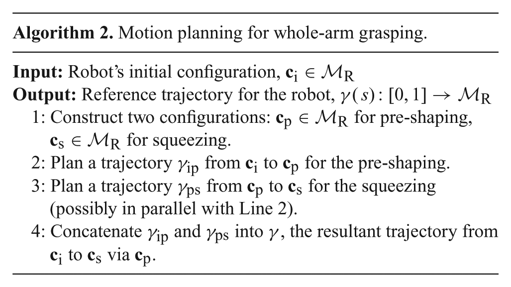
The robot is currently in configuration
It is sufficient to control the robot to follow the resultant trajectory in a quasi-static manner, by considering that only the relative configuration of the object and robot matters in caging and squeezing. In fact, the motion of the robot is necessarily interrupted on the way because it is planned to “collide” with the object. Under the assumption of being frictionless, rigid, with unilateral contact, the configuration where the robot, which is position-controlled without compliance, stops moving is an acceptable grasp that can realize a caged, equilibrium grasp by Corollary 2.
First, with friction, we can actually have more candidates for an acceptable grasp. When friction is present, the robot might get stuck on the way during a squeezing motion because non-zero friction can cause jamming and wedging (Mason, 2001). However, both phenomena imply force-closure, which in turn implies the involved wrenches are in equilibrium. Thus a jammed or wedged configuration can also be an acceptable grasp. In conclusion, friction helps improve the stability of a grasp, as also discussed by Rimon and Burdick (1998a).
Second, non-rigid objects can also be grasped stably with the algorithm. If we assume a rigid robot moving with a stiff position-control servo loop, a non-rigid object will be deformed during a squeezing motion by contact forces exerted by the robot. Since we take advantage of caging, the object will not be lost during the squeezing motion as long as the caging conditions are satisfied with the deformed geometry. The stability of a non-rigid object under a squeezing motion can be verified by online or offline computation. For online computation, we need to keep track of points of interest (for example, the vertices P and Q in Figure 7(a)) by, for example, visual deformation servoing (Navarro-Alarcon et al., 2014), and verify the corresponding caging conditions. For offline catalog work, we need to consider how to map the deformation of a wide variety of non-rigid objects by, for example, measuring contact forces or joint efforts. A squeezing motion should terminate as soon as the stability of the object is jeopardized.
7.2. Implementing whole-arm grasping
Here we present hardware/software that implements our approach to whole-arm grasping.
7.2.1. Hardware
Our idea of using effectors with curved contact surfaces in robotic grasping can be applied to a wide variety of robotic platforms; here, we employ a modular robot system, which can be a way to maximize adaptability and versatility. According to Sections 4 and 5, we may need a collection of end-effectors with a range of not only shapes but also curvature properties, for practical applications. Thus, a modular robot system with exchangeable end-effectors and attachable/detachable modular arm links allows us to quickly adapt to the sizes and shapes of a wide variety of objects.
Our robot is assembled with CKbot modules 2 (Davey et al., 2012; Park and Yim, 2009), our chain style modular robot system. Each CKbot module can be used as a one-degree-of-freedom swivel or elbow joint (Figure 16(a)). Figure 16(b) shows three subassemblies: one spine and two (left and right) arms. The spine, composed of two swivel joints and one elbow joint, provides all the three rotational degrees of freedom by realizing z–y–z Euler angles. The arms are planar manipulators composed only of elbow joints assembled such that their axes of rotation are parallel. Although Figure 16(b) shows arms composed of three modules, the modular architecture allows us to assemble more links easily.
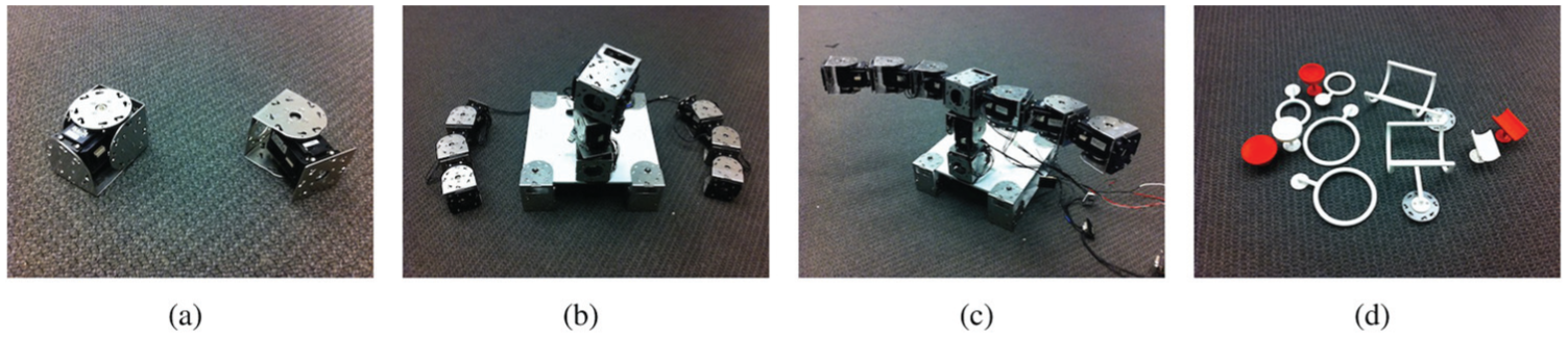
(a) Two types of CKbot modules providing one rotational degree of freedom. The left one (swivel joint) provides continuous rotation; the right one (elbow joint) is limited to 180° rotation. (b) Two three-degrees-of-freedom planar arms and a three-degrees-of-freedom spine between them. (c) A finished two-armed robot. (d) 3D printed end-effectors that can be docked to the robot.
The two arms are attached to the top of the spine such that the whole arm chain is again a planar open kinematic chain. The torque capacity of the spine essentially prevents adding more arms. Although it may not be straightforward to form the immobilizing grasps of Section 4 featuring up to three contacts with the two-armed configuration that is usually supposed to have two end-effectors, the planar chain actually suffices to realize the immobilizing grasps for the following reason. For each point, line, or planar contact, consider the net wrench that is the combination of all the contact wrenches exerted at the contact. The three (or two) net wrenches in any of our immobilizing grasps should be coplanar (from a planar pencil); otherwise, it is impossible to even guarantee equilibrium, which is necessary for immobility. Thus, three effectors appropriately positioned on the planar arm chain can form the immobilizing grasps. Our cages and squeezing motions discussed in Section 5 can also be realized by the planar architecture because two end-effectors suffice for caging and they are only required to approach to each other. In Figure 16(c), the finished two-armed robot is shown. Figure 16(d) shows 3D printed end-effectors compatible with CKbot; the effector shapes are derived from our theory discussed in Sections 4 and 5.
7.2.2. Software
Our software implementing whole-arm grasping for the hardware platform is organized as ROS
3
packages written in C++ and Python. Figure 17 shows the architecture of our software. The
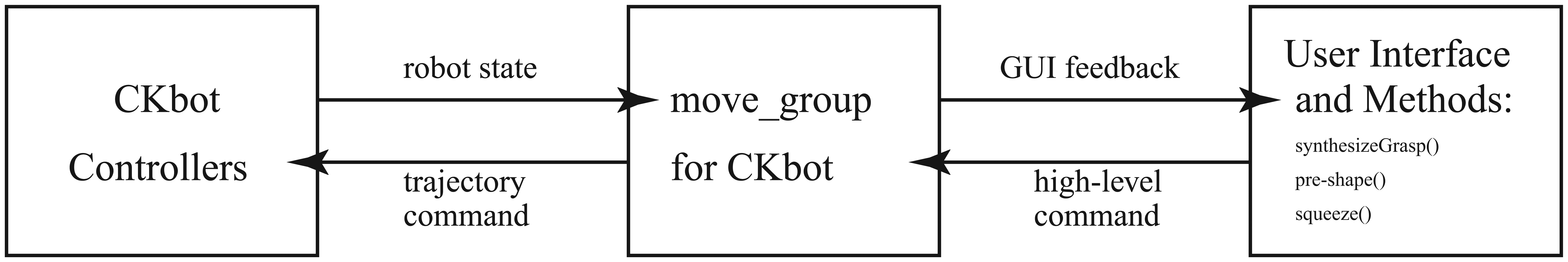
Software architecture.
First, the inverse kinematics solver for Line 1 of Algorithm 2 is based on the well-studied closed-form solutions of the inverse kinematics of a planar 3R manipulator (planar manipulator with three revolute joints); see Figure 18(a). For an arm with three CKbot modules (exactly a planar 3R manipulator), there can be two solutions commonly known as the “elbow-up” and “elbow-down” configurations. The method can also be applied to solving the inverse kinematics of an arm with n CKbot modules, where
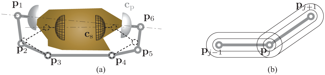
(a) The planar arm chain is composed of two planar 3R manipulators connected to the base (the longest link). At the configuration
Second, the squeezing in Line 3 of Algorithm 2 is based on energy-based motion planning. An algorithm presented by Iben et al. (2009) generates an interpolation sequence without any self-intersections between two simple polygons. In the algorithm, link lengths are allowed to be monotonically changed; this allows us to implement squeezing motions. The resultant motion basically reconfigures the two polygons “towards each other” according to a metric defined between a pair of polygons, for example, the
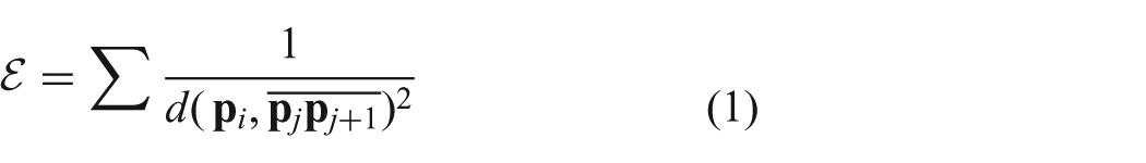
where the denominator can be the squared shortest distance between joint
7.2.3. Extending Iben et al.’s algorithm
The energy-based motion-planning algorithm explained in the previous paragraph is applicable to line segment links without joint limits, that is,
First, given narrower joint ranges (
Second, in order to avoid collisions among links with non-zero volume, we use
7.3. Experiments
A set of experiments was run to evaluate our hardware/software implementation and its performance on the task of grasping objects. We first see how accurately our robot can position its end-effectors; we then proceed to grasping objects.
7.3.1. End-effector positioning
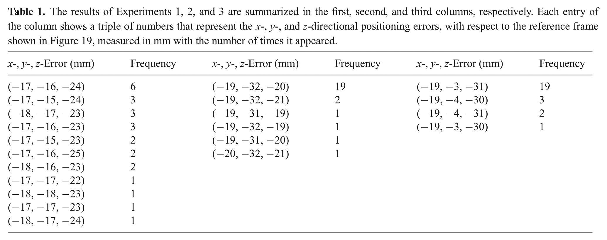
Positioning end-effectors is critical to successful grasping; thus, we first evaluated the positioning accuracy of our hardware/software implementation. We assembled a robot with two arms; each arm is composed of three link modules as already shown in Figure 16(c). We set up three target configurations for the robot such that: (1) the tips of the right and left arms are level at the same height (Experiment 1); (2) the tip of the right arm is higher than that of the left arm (Experiment 2); and (3) the tip of the right arm is lower than that of the left arm (Experiment 3). For each target configuration, a total of 25 trials was conducted and we measured the actual, final positions of the tip of the right arm using the Vicon motion capture system. 5 Figure 19 illustrates the results; Table 1 enumerates the data points measured. The average positioning error of the 75 trials was 3.73 cm.
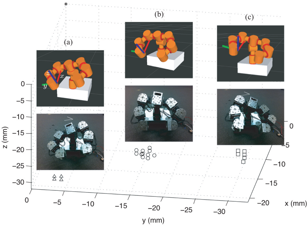
The figure illustrates the results of Experiments 1, 2, and 3. In (a), (b), and (c), the simulated robot in the upper panel shows the target configuration for Experiments 3, 1, and 2, respectively; the real robot was controlled to the targets as shown in the lower panels: the △, ◯, and □ symbols represent data points showing the actual, final positions of the tip of the right arm in Experiments 3, 1, and 2, respectively, with respect to the reference frame as shown attached at the tip of the right arm of the simulated robots. In principle, the data points were expected to coincide with the origin of the frame (see the * mark at the top of the graph).
The results of Experiments 1, 2, and 3 are summarized in the first, second, and third columns, respectively. Each entry of the column shows a triple of numbers that represent the x-, y-, and z-directional positioning errors, with respect to the reference frame shown in Figure 19, measured in mm with the number of times it appeared.
In computer simulations, there were no errors in positioning end-effectors; thus, the errors in the real experiments are mostly due to hardware such as tolerance, mechanical play, motor backlash, or compliance. Obviously, the positioning errors are not negligible by considering that each arm is approximately 30 cm long. The arm length of the robot can be compared with the arm length of infants (the mean of the upper arm length of infants aged 3–5 months is 12.8 cm (McDowell et al., 2008)); for comparison, it is known that neonate infants can position their hands within 1.5 cm of objects, which they touch or occasionally grasp (Bower, 1970).
7.3.2. Whole-arm grasping
The positioning experiments suggest the appropriate sizes of end-effectors for successful grasping without position calibration. Figure 20 shows the CAD models of our end-effectors fabricated for grasping experiments. The dimensions of the effectors were determined to address the x- and z-directional positioning errors (recall Figure 19 for the axes and Table 1 for the error data). For example, for the torus-shaped effector in Figure 20(a), the inner radius of the torus was determined to be 46 mm, larger than the maximum positioning error on the xz-plane from Experiments 1, 2, and 3; for the cylindrical effector in Figure 20(b), the inner radius of the cylinder was also determined to be 46 mm for the same reason. The end-effectors are supposed to be squeezed along the y-axis; thus, the y-directional errors can be addressed by our approach that takes advantage of squeezing. Although the end-effectors appearing in Figure 20 look different from the examples in Section 5.1, the end-effectors are sufficient to grasp objects based on Theorem 3 and Corollary 2 in that their geometry is more conservative than the examples. For example, the torus-shaped end-effector in Figure 20(a) can be regarded as the boundary of the hemispherical effector in Section 5.1; moreover, the torus-shaped effector was empirically analyzed in Section 5.2.
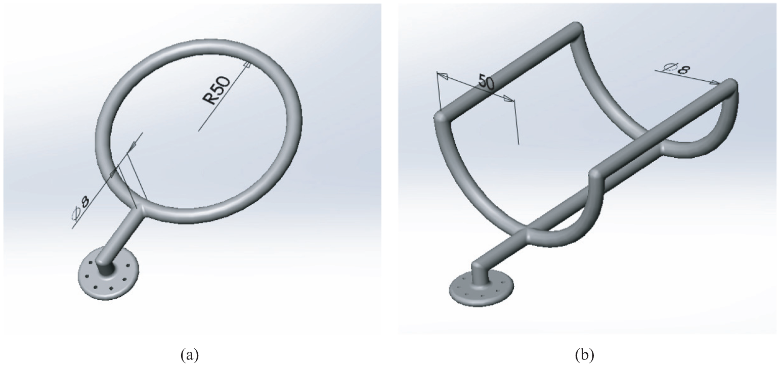
(a) A torus-shaped end-effector. (b) A cylindrical end-effector; in the model, material usage was minimized to reduce weight and cost. The units are in mm.
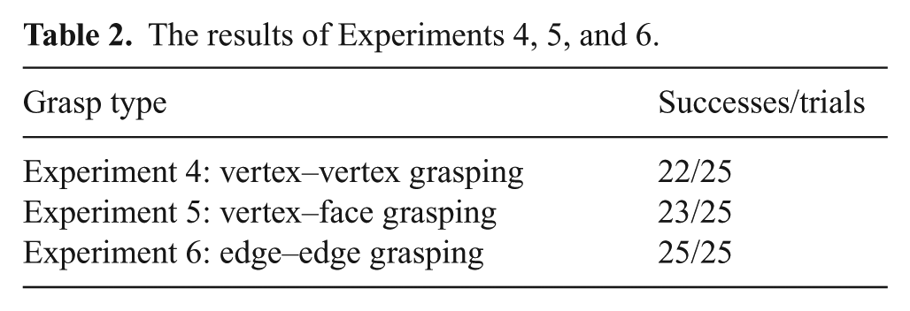
We ran three sets of experiments to evaluate the capability of our system: grasping an object using its vertex–vertex pair (Experiment 4), vertex–face pair (Experiment 5), and edge–edge pair (Experiment 6). In each set of experiment, a total of 25 trials was conducted and we verified if the robot could grasp an object, perceived by the Vicon system, via pre-shaping and squeezing without any position calibration. The results are summarized in Table 2.
The results of Experiments 4, 5, and 6.
The snapshots in Figure 21 show the robot grasping objects via pre-shaping and squeezing, demonstrating Theorem 3 by showing that caged, equilibrium grasps can be obtained from our cages, and verifying the soundness of our approach to whole-arm grasping (Corollary 2). The robot was controlled until joint torque saturation occurred during the squeezing. The final grasps shown in the rightmost panels of Figure 21 were obtained from cages on a vertex–vertex, a vertex–face, and an edge–edge pair discussed in Section 5. According to Corollary 1, the way the robot is grasping the box in Figure 21(a) can be applied to any polyhedral shape; almost all polyhedral shapes can be grasped in exactly the same way as grasping the tetrahedral object in either Figures 21(b) or (c). In the failed trials, the two arms were moving in an asynchronized manner (possibly due to an unexpected communication error) or the end-effectors were dynamically interacting with the object (or the support under the object).
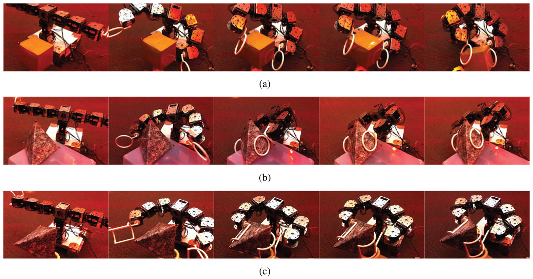
(a) The robot is grasping the box with the two torus-shaped end-effectors that can cage and grasp the vertex–vertex pair. (b) The robot is grasping the tetrahedral object also with the two torus-shaped end-effectors that can cage and grasp the vertex–face pair; one of the torus-shaped effectors was used to contact the face. (c) The robot is grasping the tetrahedral object with the two cylindrical end-effectors that can cage and grasp the edge–edge pair.
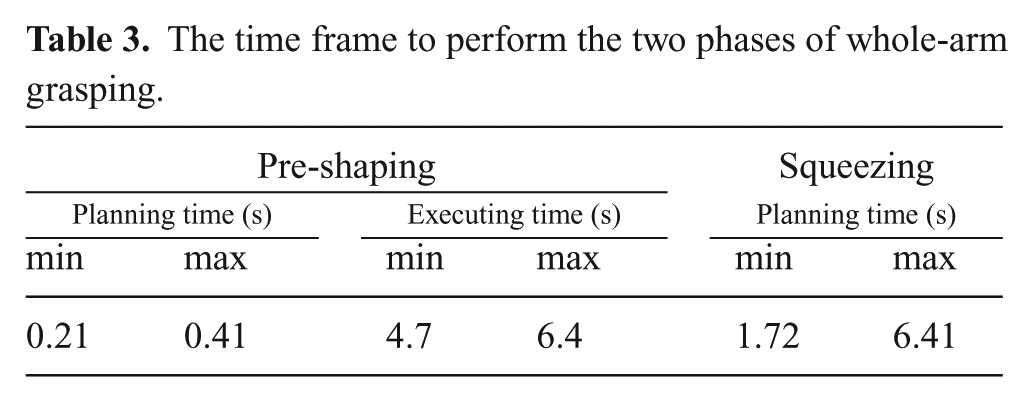
Finally, Table 3 shows the average time frame to perform pre-shaping and squeezing, for 25 trials. In the table, the planning times show how long it takes to run the respective software components (
The time frame to perform the two phases of whole-arm grasping.
8. Conclusion
We have presented three types of immobilizing grasps and cages and shown that they can be applied to a wide range of object shapes including polyhedra. Each of the grasps or cages is formed by at most three effectors with appropriately curved contact surfaces. The immobilizing grasps depend on the local curvature properties of the effectors, whereas the cages are formulated by global parameters, such as the distance between the effectors. A stable grasp can be obtained from any of our cages by a squeezing motion; it also allows us to get a whole-arm grasp. In the Appendix that follows, the collection of the complete grasps and cages is extended to include more types of grasps and cages for two- or three-dimensional objects. Our theory was implemented on a modular robotic platform that can enhance the versatility and adaptability needed in robotic grasping, compared to a customary manipulator with a fixed configuration. Not only pick-and-place tasks, but also a variety of post-grasp manipulation tasks can potentially be facilitated by the secure grasps using the effectors with curved contact surfaces.
Our future research directions include extending the theory, enhancing autonomy, and finding more applications. First, our theoretical framework can be extended in a number of directions. In order to guarantee performance under frictional, compliant contact, the effects of friction and compliance should be treated in a more quantitative manner. Approaches may include incorporating accurate and tractable models of finger–object contact, contact friction, and the compliance of the robot joints and links. Second, there are many great benefits to enhanced autonomy. For example, autonomous robotic systems can eliminate human errors and work safely in dangerous environments such as outer space or the ocean floor. Our objectives for enhancing autonomy include incorporating more sensing capabilities; for example, visual sensing will be beneficial to not only perceiving objects to grasp but also guaranteeing the safety of squeezing motions. The level of autonomy can also be greatly increased by enabling proper interaction with the environment, which will facilitate grasping an object in clutter. Another interesting direction is to develop hardware and software supporting efficient self-reconfiguration: such a system can adapt itself to grasp an arbitrary object by autonomously exchanging end-effectors or attaching more arm links. Third, effectors with curved contact surfaces can be used as not only “hands” but also “feet” for walking or running. RHex (Johnson and Koditschek, 2013; Saranli et al., 2001) showed the versatility of single-bodied legs without any internal degrees of freedom; leg stiffness will be an important factor as discussed by Galloway et al. (2011). Our approach can also be useful in manufacturing, eliminating the need of redesigning fixtures according to objects.
Footnotes
Appendix: Extending our theory
Here we discuss how to extend the collection of the grasps/cages presented in Sections 4 and 5: more types of grasps/cages can be added by employing other types of antipodal pairs. We also discuss grasping and caging two-dimensional objects with curved effectors on the plane.
We first show that it is possible to immobilize a polyhedron with one point and one line contact made by curved effector surfaces, which are frictionless, rigid, unilateral. See Figure 22(a). O and
For a differential twist
Then, the solutions are of the form:
because
This is a zero-pitch screw (pure rotation) where the first three components give the direction of the rotation axis, which should pass through O. This rotation instantaneously moves
We additionally show that it is possible to immobilize a polyhedron with one planar and two point contacts made by curved effector surfaces, which are frictionless, rigid, unilateral. See Figure 22(b). Consider an edge–face pair that determines the width of the convex hull of the given polyhedron, denoted as
where
The objects in Figures 22(b) and (c) are also caged by the three effectors. One approach to establishing a grasping function here is to assume a control strategy that moves the three effectors as a three-fingered gripper system with one parameter that controls the opening of the gripper, as also discussed by Davidson and Blake (1998a) for three point fingers. Let
As a corollary, every polygon can be caged by two curved effectors: the effectors in Figures 23(a) and (b) are also caging the polygon. Sufficient conditions for caging can be derived by applying the results of Sections 5.1 and 5.2 (see the similarity between Figure 8 and Figure 23(a), or between Figure 9 and Figure 23(b)).
We can also add more types of grasps and cages; for example, as shown in Figure 23(c), two-point effectors suffice to immobilize/cage some concave polygons as discussed by Vahedi and van der Stappen (2008a).
Funding
We gratefully acknowledge the support of the NSF (grant numbers 1328805 and 1138847) and the ARL (grant number W911NF-10-2-0016).