
Abstract
This paper presents the design, analysis, fabrication, experimental characterization, and evaluation of two prototypes of robotic extra fingers that can be used as grasp compensatory devices for a hemiparetic upper limb. The devices are the results of experimental sessions with chronic stroke patients and consultations with clinical experts. Both devices share a common principle of work, which consists in opposing the device to the paretic hand or wrist so to restrain the motion of an object. They can be used by chronic stroke patients to compensate for grasping in several activities of daily living (ADLs) with a particular focus on bimanual tasks. The robotic extra fingers are designed to be extremely portable and wearable. They can be wrapped as bracelets when not being used, to further reduce the encumbrance. Both devices are intrinsically compliant and driven by a single actuator through a tendon system. The motion of the robotic devices can be controlled using an electromyography-based interface embedded in a cap. The interface allows the user to control the device motion by contracting the frontalis muscle. The performance characteristics of the devices have been measured experimentally and the shape adaptability has been confirmed by grasping various objects with different shapes. We tested the devices through qualitative experiments based on ADLs involving five chronic stroke patients. The prototypes successfully enabled the patients to complete various bimanual tasks. Results show that the proposed robotic devices improve the autonomy of patients in ADLs and allow them to complete tasks that were previously impossible to perform.
1. Introduction
Robotic applications have rapidly grown from classical industrial applications with repetitive tasks to applications with close human–robot interaction. In particular, assistive robotics has gained increasing attention in the last decades (Van der Loos and Reinkensmeyer, 2008). Assisting robotic devices can have a great impact on the adaptation of healthcare services to the needs of an increasingly dependent population (aging, degenerative diseases, etc.). Technological advances and the emergence of novel adapted technologies, such as wearable technologies, with considerable reduction in size, cost, and energy consumption are becoming a popular solution to provide assistive services to human beings. This capable technology is expected to work closely, interact, and collaborate with people in an intelligent environment. While initially conceived for human motion augmentation purposes, wearable powered robots have gradually been proposed as a technological aid for motion rehabilitation and assistance, and functional substitution in patients with motor disorders (Pons, 2008).
In this paper, we focus on a novel wearable assistive technology for chronic stroke patients. Stroke is one of the leading causes of long-term impairment. On average, every 40 s, someone in the USA has a stroke (Go et al., 2014). Impairment of the hand-grasping function is one of the common deficits after a stroke: approximately 60 % of stroke survivors experience some form of sensorimotor impairment associated with a hand (Nowak, 2008). Different motor impairments can affect the hand both at motor execution and motor planning or learning level. Deficits in motor execution include weakness of wrist or finger extensors, increased wrist or finger flexor tone and spasticity, co-contraction, impaired finger independence, poor coordination between grip and load forces, inefficient scaling of grip force and peak aperture, and delayed preparation, initiation, and termination of object grip (Balasubramanian et al., 2010; Raghavan et al., 2006). Recovering hand functions is of primary importance during the rehabilitation phase. Many wearable devices have been proposed in the last decade, especially for hand rehabilitation and function recovery. A review of robot-assisted approaches to motor neurorehabilitation is given by Lum et al. (2012). However, most of the devices are designed to increase functional recovery in the first months of rehabilitation therapy, when biological restoration and reorganization of the central nervous system can take place. However, only 5% to 20% of patients show a complete recovery of upper limb 6 months after a stroke (Nakayama et al., 1994). When the motor deficit is stabilized in the paretic upper limb, rehabilitation mainly consists of ergotherapy, with the primary focus of teaching compensatory strategies, which may often take advantage of dedicated aids. These strategies are sometimes neither ergonomic nor ecological (Davis and Burton, 1991), even increasing pathological motor patterns, usually by worsening tonic flexion at the forearm of the paretic limb (Michaelsen et al., 2004). Various compensatory aids are commercially available to support patients in activities of daily living (ADLs) (Gillen, 2015). The main target of these dedicated tools is to let typical bimanual tasks be executed using only the unaffected hand, increasing the disparity between the two upper limbs. Moreover, these tools can be difficult to carry outside structured environments, limiting their use to rehabilitation facilities or to the patient’s house.
A possible solution is that of using a wearable compensatory robotic device that can work together with the paretic upper limb to compensate the missing abilities of the impaired hand. These devices should, for example, recover the ability to grasp and stabilize objects, while motivating the patient to use the residual mobility of the_ paretic upper limb. Moreover, a wearable robotic device could easily be carried by patients, even outdoors. Finally, a single robotic device could replace many commercially available tools for performing ADLs, since these tools are generally designed to perform a single task each.
Existing compensatory robotic devices, like prostheses, cannot be used for this purpose, since the hand of the patient, although frequently with limited mobility, is still present. Early results on the replacement of the impaired hand with robotic devices have been reported (Aszmann et al., 2015). However, this potential solution could be much less effective in chronic stroke patients, where the whole arm often presents limited residual mobility. Exoskeletons are another kind of assistive device, where an external mechanism with joints and links is coupled with the corresponding joints of the human limbs. Heo et al. (2012) presented a comprehensive review of hand exoskeleton technologies for rehabilitation and assistive engineering. Rigid exoskeletons do not accommodate variations in patient skeletal structure or joint misalignment and can produce compression forces on the soft tissue and joints during long-term use (Pons et al., 2004). Moreover, most of the proposed exoskeletons are cumbersome, limiting the wearability and portability of the device.
Besides exoskeletons and prostheses and their working principles, it is interesting to study other robotic solutions that can compensate the missing grasping function. The aim is to come up with a robotic device that can work together with the paretic upper limb instead of replacing it and without causing any unnatural forces. In robotics, one of the simplest structures that allows grasping is the gripper. Industrial grippers usually have two fingers and only one degree of freedom. Further simplifying, one finger can be seen as a fixed palm and the other one as an active finger, able to restrain the motion of an object. If we consider the paretic upper limb of the patient as a potential fixed palm, what is really missing is an active finger able to perform the grasp. In this view, robotic extra fingers can represent a minimal complexity solution that also guarantees extreme wearability and that does not need to be coupled to human impaired limbs to compensate for missing capabilities. Such devices could enhance manipulation capability without relying on the user’s skeletal structure for support, making anatomical variation and motion restriction a lesser issue.
Recently, research groups at the Massachusetts Institute of Technology and the University of Siena independently developed ideas and prototypes of robotic extra fingers. Wu and Asada (2014) presented a design with two supernumerary robotic fingers. A method for controlling extra robotic fingers in coordination with human fingers to grasp diverse objects has been further developed (Wu and Asada, 2016). Although two independent extra fingers showed great potentialities in augmenting human hand functions in healthy subjects, size and proposed control strategies limit their possible application as assistive device. Toward the direction of active assistive devices, we have started investigating (Prattichizzo et al., 2014a,b) a wearable robotic extra finger to be used in cooperation with the paretic limb to recover the capability of grasping objects. We have reported some preliminary results (Hussain et al., 2015b) on the use of a modular robotic structure as an active compensatory tool for chronic stroke patients. In particular, the extra finger prototype was worn on the paretic forearm by means of an elastic band, and was coupled with a vibrotactile ring interface worn on the healthy hand. The robotic finger and the paretic hand acted like the two parts of a gripper working together to hold an object. The user was able to control the flexion and extension of the robotic finger through a switch placed on the ring, while being provided with vibrotactile feedback about the forces exerted by the robotic finger on the environment. We introduced (Salvietti et al., 2016) an EMG interface to control the finger flexion and extension as well as a compliance control to let the finger adapt to the shape of the grasped object. Finally (Hussain et al., 2016), we proposed a preliminary version of an underactuated compliant extra finger. The proposed robotic devices were used by patients to perform clinical assessment tests, but the systems had limitations in performing common ADLs. Those limitations were associated with the performance characteristics of the robotic devices and with the limited capability of a single finger to perform particular tasks, e.g., pouring water from a bottle. The device limitations were mainly due to low actuator torque, low friction at contact areas, and weak coupling of the device at the forearm.
In this paper, we present two novel prototypes of wearable grasp compensatory devices for a hemiparetic upper limb: the soft sixth finger and the double soft sixth finger, see Figure 1.
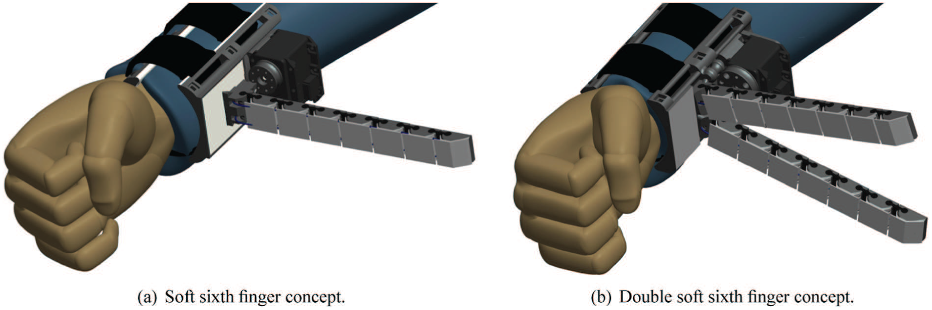
Proposed wearable robotic compensatory devices for hemiparetic upper limb. Left: a single extra finger is proposed to compensate for missing hand-grasping function. Right: a double finger is proposed to increase the grasp stability and payload.
The former is an improved version of the device presented in Hussain et al. (2016). The new design shares some features with the previous device in terms of wearability, robustness, and ability to adapt to different object shapes. However, the upgraded version has a new actuator with increased torque, a silicone skin to increase friction, double tendon actuation to improve torsional rigidity, and a new support base design to provide stable grip at the forearm. The double soft sixth finger device has been designed to improve grasp stability in more payload-demanding tasks. We doubled the flexible structure of the device to obtain two fingers. The two fingers are attached to a base that can be worn at the user’s forearm. The device is actuated by a single motor and the two-finger design improves grasp stability and robustness. An improved version of the eCap, an EMG interface embedded in a cap, proposed in a preliminary version in Hussain et al. (2016), is also presented in this paper.
We evaluated the performances of the assistive system through an experimental setup. The results showed major improvements in the performance characteristics of the devices, in particular grasp stability, fingertip force, and maximum payload. Such improvements led to successful experiments with the patients in performing various ADLs tasks. Our devices were tested by five patients selected by the clinical team, based on the criteria explained in Section 4. The experiments focused on bimanual activities related to the kitchen and on the use of mechanical tools. During all the tasks, patients used the robotic finger and the paretic limb to hold the object while the unaffected hand was used to perform manipulation on it. A main contribution of this work is the evaluation of the effectiveness of wearable extra robotic fingers as compensatory tools for chronic stroke patients in ADLs, where bimanual tasks are involved. The rest of the paper is organized as follows. In Section 2, we present the mathematical model of the robotic finger, used for determining device specifications, design, fabrication, and experimental characterization of the proposed robotic devices based on flexible structure. The control interface is detailed in Section 3, while the experiments with chronic stroke patients are presented in Section 4. Results and discussion are given in Section 5. Finally, conclusions and future work are outlined in Section 6.
2. The soft sixth finger and the double soft sixth finger
The wearable assistive robotic devices used for clinical applications must meet specific human factors and performance criteria. The general guidelines that can be found in the literature include: durability, energy efficiency, low encumbrance, ease of use, error tolerance, and configurability (Meng and Lee, 2006). The specific performance criteria and human ergonomics strongly depend on the actual patient conditions and needs (Miguelez et al., 2004; Stanger et al., 1994). To improve the wearability and acceptability of the devices for the users, the design must meet a number of conditions related to ergonomics and functionality (Pons, 2010). Several experiments with the patients conducted in cooperation with a rehabilitation team reported in Hussain et al. (2015b, 2016) and Salvietti et al. (2016) led us to outline the main functional requirements and human factors, as reported in Table 1. We considered these ergonomics and functional requirements in the design and development of the proposed robotic devices. Table 2 summarizes how we met these requirements in our devices; the detailed design and development methodologies are explained in corresponding sections. The compensatory devices have been designed to be wearable, robust, and adaptable to different object shapes. In general, the robustness plays two roles. First, it enables the robotic devices to grasp objects reliably in the presence of large sensory uncertainty. Second, it enables the devices to withstand large impact and other forces, owing to unintended contact with the environment. The robustness and soft interaction are mainly achieved by either regulating the compliance of robotic joints (Vanderborght et al., 2013) or tuning the intrinsic softness, acting on the passive characteristics of the robot bodyware (Dollar and Howe, 2011; Laschi and Cianchetti, 2014; Ma et al., 2015). The former approach is based on complex and often bulky variable impedance actuators. Our devices are inspired by the latter approach to be simple, lightweight, and compact. The proposed devices are based on the principle of an underactuated cable-driven flexible and modular structure, as shown in Figure 2. The passive compliance in the joints guarantees robustness and safety during interaction with the environment. The devices can endure collisions with hard objects and even strikes from a hammer without breaking into pieces.
Ergonomics and functional requirements.
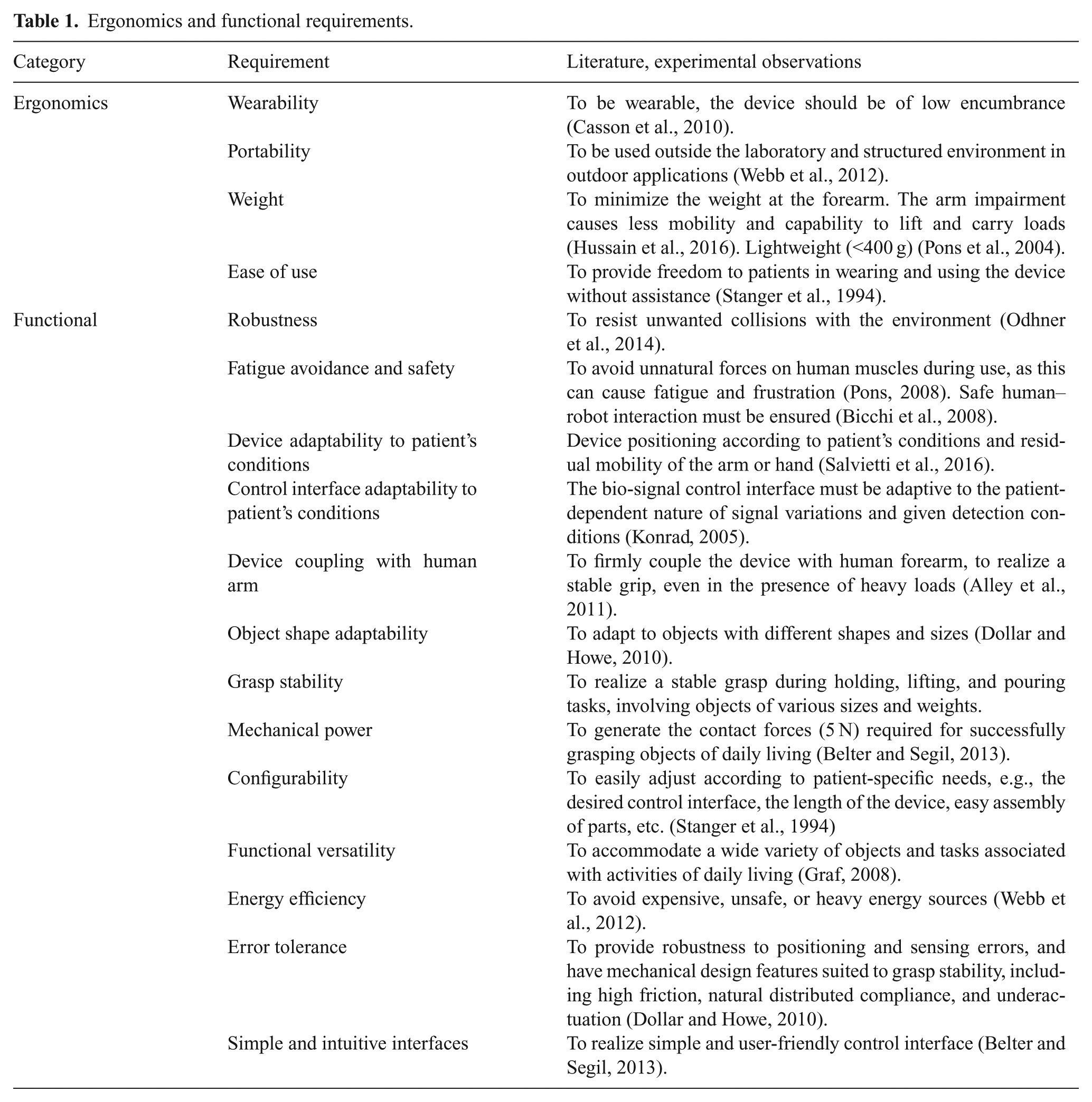
How the proposed robotic devices meet the ergonomics and functional requirements listed in Table 1.
Underactuated cable-driven flexible finger. The finger has modular structure. Each module is composed of soft and stiff parts.
In addition to this, the actuation system of the proposed devices resembles that of underactuated robotic hands (Birglen et al., 2008). Underactuated hands have desirable adaptability to shapes, and can be effectively implemented using relatively simple differential and elastic elements. The transmission solutions allow motion of other joints to continue after contact occurs on a coupled link, allowing the hands to passively adapt to the object shape (Dollar and Howe, 2010). Passive adaptability allows one to drive the device with a reduced number of control parameters. The built-in compliant nature of the extra fingers and underactuation increase their ability to grasp different objects. They can adapt their shape to that of the grasped object. Shape adaptation increases the grasp performance by compensating the uncertainties in sensing and actuation and helps in stabilizing the grasp (Eppner and Brock, 2013). Robustness and intrinsic compliance is realized through the cable-driven flexible structure of the robotic fingers.
A mathematical model, presented in Section 2.1, was used to study the kinematics of such a cable-driven flexible finger and to simulate its bending profile. The simulation results helped in minimizing the manufacturing iterations, in particular adjusting the stiffness in each joint to obtain a desired finger-closing trajectory and the length of the finger to cover a certain workspace. In Section 2.2, the design, development, and performance evaluation of the soft sixth finger is given. Section 2.3 describes the design, development, and preliminary evaluation of the double soft sixth finger. Wearability and device position at the forearm according to the patient’s condition are detailed in Section 2.4.
2.1. Static analytical model and analysis
A mathematical model of a cable-driven flexible finger is developed to minimize the number of manufacturing iterations and to study the kinematics of a flexure-based multi-jointed robotic finger. In particular, the model is analyzed:
To determine the fingertip deflection in response to the actuator’s force;
To observe joint deflection variation by changing the density of the flexible part;
To estimate the minimum size of self-enveloping graspable object with selected length of the finger and deflection (stiffness) in each joint.
Unlike simple revolute joint-based serial kinematic chains, the flexural nature of flexible fingers needs a modelof flexural mechanics coupled with a kinematic model to study the finger behavior. A model for a flexible robotic gripper was proposed by Gafford et al. (2014), in which the trajectory of the finger is regulated by choosing the different lengths of each link. In this work, we adapt that model to act on the stiffness of flexible joints in order to regulate the trajectory of the proposed flexible modular finger.
To derive a static analytical model, let us consider a single module, as shown in Figure 3, composed of a flexible part (subscript
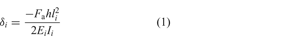
where
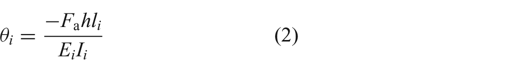
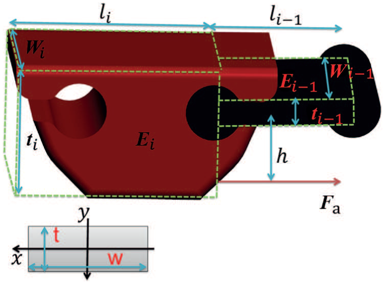
Module geometric and material parameters. The module consists of flexible part (
For the sake of simplicity, we neglect the deflection of the joint in the lateral and torsional directions. This simplification was validated through finite element method based simulations and stress/deformation analysis presented in Hussain et al. (2017a). We observed that, for our designed geometry of the flexible joint, the lateral and torsional stiffness is higher than the bending stiffness.
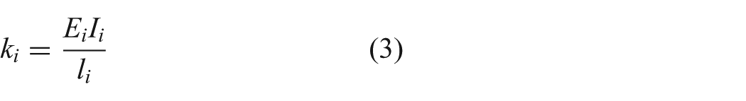
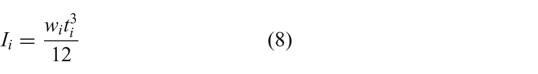
The rotational stiffness of the joint can then be evaluated as
The tendon pulling force (
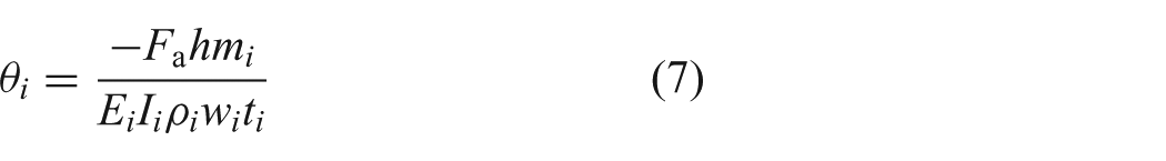
To achieve a certain closing trajectory of the flexible finger, we need to have a different deflection in each joint, under the same applied force. In Hussain et al. (2017a), we proposed a detailed mathematical framework to design and develop the stiffness of flexible joints necessary to generate the desired trajectory of the supernumerary robotic fingertip inspired by the first synergy of the human hand. Here, we recall the main part of the model, which focuses on the hardware realization of soft joints of given stiffness. Referring to equation (1), different deflections and joint angles under the same applied force can be achieved by changing the geometric or material parameters of the modules. Since we want a modular structure, the geometric parameters are the same for each module. Conversely, we can tune the material parameters to achieve variable joint deflection ofthe robotic finger. In particular, by keeping in view the intended 3D printing fabrication method, we can transform the equations (1) to (4) in terms of a density parameter. Thus, flexible parts can be printed with different percentages of infill density to obtain different deflections while maintaining the same geometric shape of the parts.
The density (
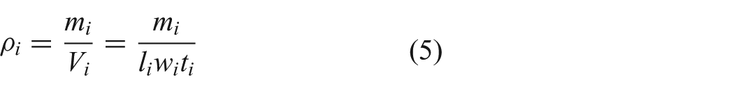
Thus, rewriting equations (1) and (2), we get
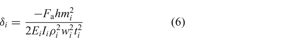
Assuming that each part of the module is a filled rectangular shape, whose centroid is located at the origin, the second moment of area with respect to the x -axis can be approximated as
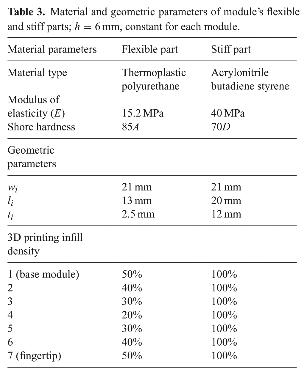
The mathematical model can be extended to any number of modules. We selected seven modules to achieve the length of the finger equal to the average size of a human hand (Schwarz, 1955), approximately. We simulated the model of the complete flexible finger, adapting the model available on the open-source platform Soft Robotics Toolkit (Holland et al., 2014). In particular, we added the possibility of changing the stiffness of the soft joints by varying the percentage of infill density. The overall deflection at the fingertip can be determined by propagating the internal moments generated by the tendon tension back to the base module. We defined the global frame of reference at the base module and transformed the local deflection into the global frame using the homogeneous transformation matrices given in Appendix B. We simulated the analytical model with different density percentages for each joint to set the trajectory of the finger for maximum enveloping grasp. The final density percentage for each module is listed in Table 3. We 3D-printed the flexible parts with the resultant percentages of infill density to achieve different deflections in the joints under the same applied tendon force. We estimated the minimum size of a self-enveloping graspable object as 2.3 cm, with a selected length of the finger of 18 cm.
Material and geometric parameters of module’s flexible and stiff parts; h=6 mm, constant for each module.
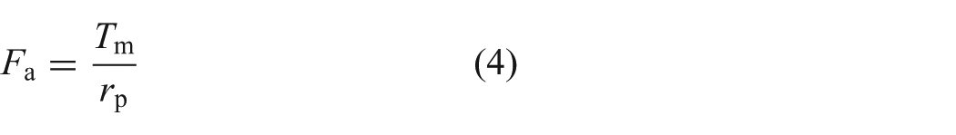
The proposed model can be further exploited to relate the fingertip force to the actuator force. The force applied by the actuator through the tendon produces a moment about the flexible part of the finger. The resultant behavior can be approximated by a simplified cantilever beam model. The two forces acting on the model are the actuator-applied force and the resultant reaction force, which is equal to the fingertip applied force
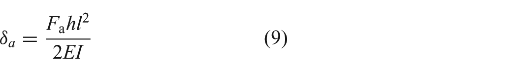
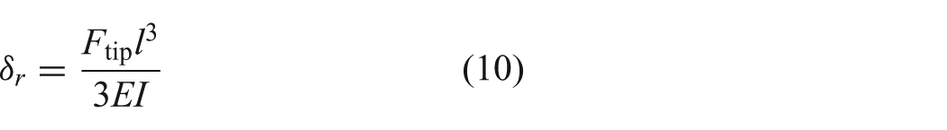
The sum of both deflections can be equated to zero and the resultant equation is solved for
Note that the terms E and I are canceled out of the equation and as a result we do not need to consider the interaction between the alternating stiff and flexible parts of the modules to obtain the overall load at the fingertip. The model can be extended to any number of modules, as
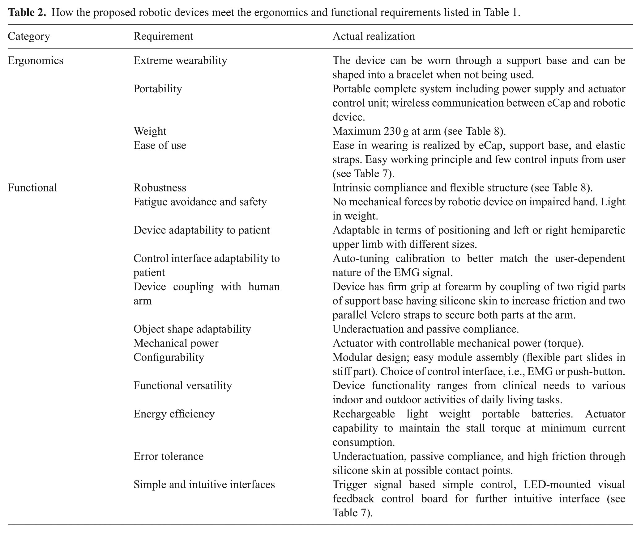
Furthermore, we can consider the parasitic capstan effects that take place between the cable and stiff parts as the robotic finger transforms to a curve shape, as shown in Figure 2. As the modules lose colinearity during their motion, the cable imparts a reaction force that resists further actuation. We can include the capstan effect by considering the angle between subsequent stiff parts of modules (
where
Figure 4 shows flexible finger trajectories based on the presented mathematical model. We simulated the model with different density percentages for the flexible parts to observe the finger trajectory variation. The final selected density percentage of each flexible joint for the developed prototype is listed in Table 3. The selected trajectory is reported in the right panel of Figure 4.
Simulation results of flexible finger trajectory: flexible part (blue) and stiff part (red). Different closing trajectories of the finger are plotted. The variation in trajectory is achieved by setting different density percentages of the flexible parts. The trajectory selected for the soft sixth finger is shown in the plot on the right.
We validated our method through an experimental setup. We built the soft finger, using the different percentage of infill density for the soft joints reported in Table 3. We tracked the fingertip trajectory of the device using a Vicon system (Vicon Capture Systems, UK) consisting of eight cameras. We compared the mean of five recorded trajectories of the fingertip with that computed through the mathematical model, as reported in Figure 5. The mean error between the simulated trajectory and the experimentally evaluated trajectory was 0.023 m along the x -axis and 0.021 m along the y -axis, while the maximum errors were 0.04 m and 0.027 m for the x and y axes, respectively. This error results from different factors, including the 3D printed accuracy in density regulation, unmodeled friction between the tendon and the stiff part of the modules and small finger fluctuations during the flexion motion. However, this error did not impact on the usability of the extra finger, as reported in Section 4.
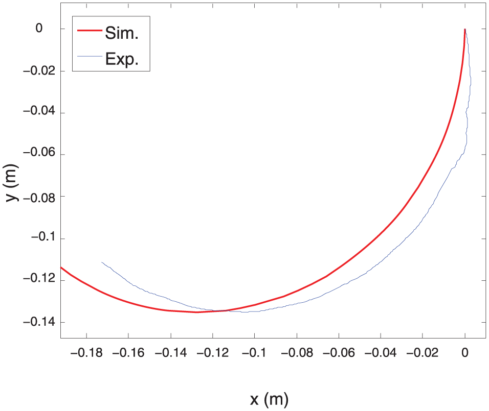
Trajectory of the fingertip of the soft sixth finger; simulated (red) and experimentally evaluated (blue). Simulations were obtained using the model presented in Section 2.1. Experimental data were obtained using an optical tracking system.
2.2. Soft sixth finger
2.2.1. Design and manufacture
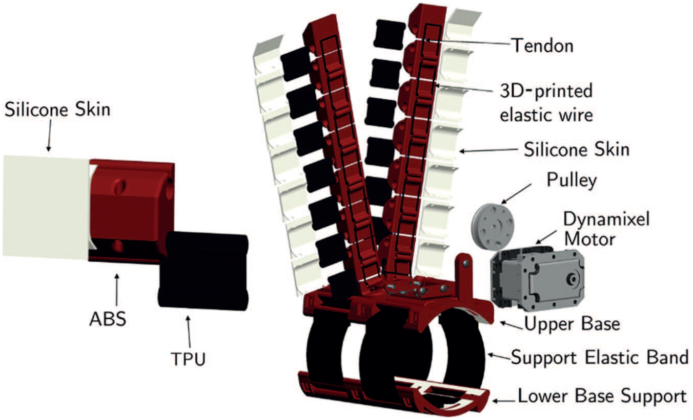
The soft sixth finger is composed of two main parts, a flexible finger and a support base, as shown in Figure 6. The flexible finger is built with a modular structure. Each module consists of a rigid 3D printed link realized in ABS (acrylonitrile butadiene styrene, ABSPlus, Stratasys, USA) and covered with a silicone skin and a 3D-printed thermoplastic polyurethane part (Lulzbot, USA) that acts as the flexible joint. We selected polyurethane for the flexible parts because the high elasticity of this material allows for repeated movement and impact without wear or cracking; it also provides excellent vibration reduction. The reasons for adding passive elements are manifold, including storing elastic energy, avoiding tendon slackness, passive compliance, the distribution of forces over a large contact area, and ensuring the uniqueness of the position (Catalano et al., 2014).
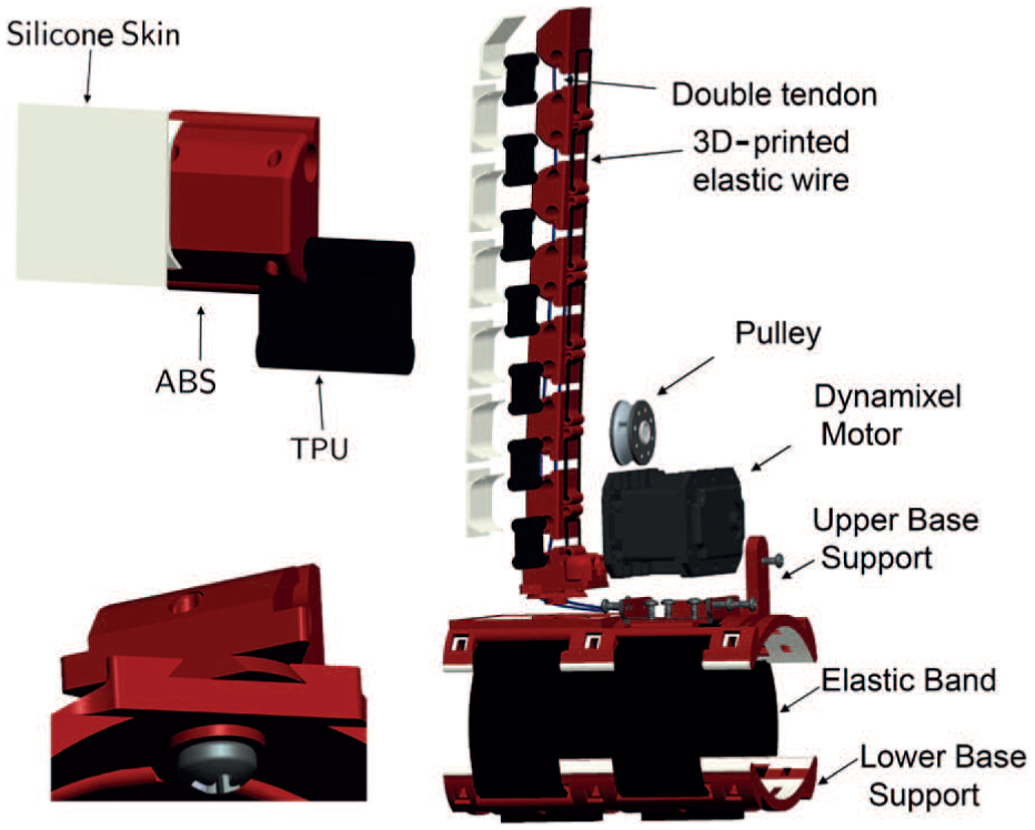
Exploded CAD view of unit module, complete soft sixth finger, and dovetail passive locking mechanism. Two holes in the module for the double tendon, the modular structure of the device, the support base, and the actuator are shown.
The modules are connected by sliding the thermoplastic polyurethane part into the ABS part. This method makes the assembling process easy without using screws or passive elements to combine the modules. The length and closing trajectory of the device were selected according to the procedure presented in Section 2.1. The device is designed and developed by combining two different manufacturing processes, i.e., 3D printing and molding. The skeleton of the device is fabricated by rapid prototyping 3D printing, while the silicone skin is realized by a molding process. The molding process shapes the raw material using a solid frame of a particular shape, called a pattern. We used a 3D-printed skeletons to hold the liquid silicone in the desired shape until it turned solid. We used closed-top molds, which are used for more complex part geometries. We poured the silicone mixture over the skeletons of the modules and support base and used the other mold parts to constrain the liquid silicone to achieve the desired geometry and shape of the skin. Metal tubes were inserted into the module holes to avoid silicone filling the tendon holes. The top row of Figure 7 shows an exploded view of the parts used in the molding process; the bottom row shows the assembled configuration of parts during the curing process of liquid silicone. The silicone used is Fast Rubber FR-18, which is bi-component and cures at room temperature. The mixing ratio of components is 100 g of resin per 5 g of hardener. It has a viscosity of 30 Pa
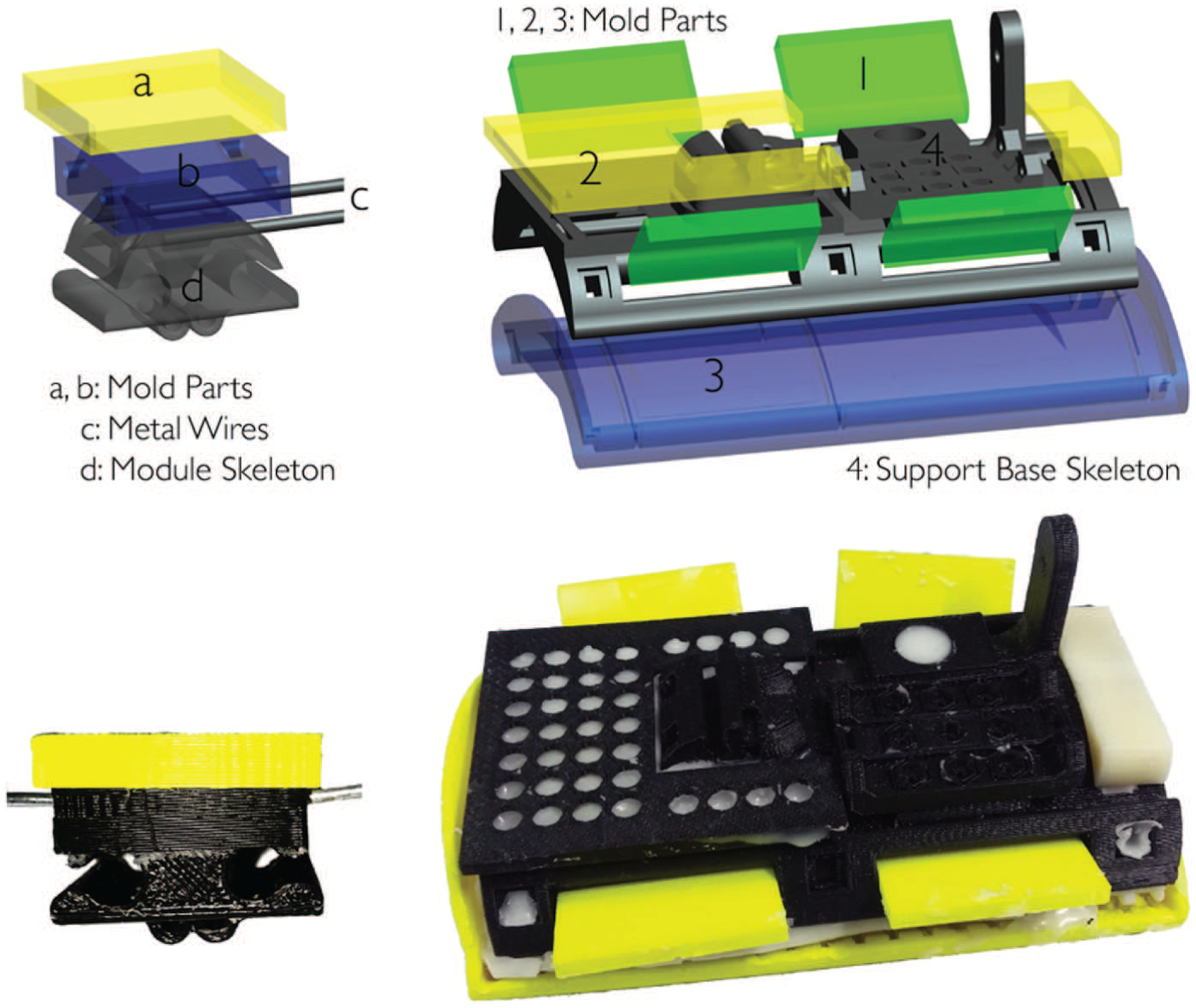
Molding process to realize silicone skin. Mold parts, module skeleton, and support base skeleton are 3D printed. Metal wires are inserted in the tendon wire holes to avoid silicone infiltration.
The support base of the device was designed to assure a firm grip on the arm. The ergonomic design of the support base guarantees the stability of the device in withstanding the applied load. The support base consists of two parts coupled with Velcro strips to facilitate wearing the device at the forearm and guarantee adaptation to different arm sizes. The upper part contains the actuator and base module of the robotic finger. Both parts are covered with a silicone skin to increase comfort and stability at the forearm. The skeleton of the support base is 3D printed in ABS and the silicone skin is realized through a molding process. The support base and the flexible finger are coupled through a dovetail triangle locking mechanism, which is described in detail in Section 2.4. This mechanism is used to switch between the working and rest positions of the devices. The structure of the support base is symmetric, a feature that enables the robotic devices to be worn on either the left or the right arm without modification.
The device actuation is achieved by using a single actuator and two tendons running in parallel through the modules of the finger. The holes in the rigid links allow the passage of the cables (polyethylene Dyneema Fiber, Japan) which are used to realize the tendon-driven actuation. The tendon wires run through the finger and are attached at one end to the fingertip and at the other end to a pulley rigidly connected to the actuator shaft. When the motor is actuated, the tendon wires are wound on the pulley, reducing the length of the wire and thus flexing the finger. As the motor is rotated in the opposite direction, extension of the finger is achieved, thanks to elastic force stored in the flexible parts of the modules. The actuator used is the Dynamixel MX-28T (Robotis, South Korea). Principal details of the motor features are reported in Table 4; for a complete description, the reader is referred to (Robotis© 2012). We used an ArbotiX-M Robocontroller (ArbotiX© 2012) to drive the Dynamixel motor. This control solution for Dynamixel motors incorporates an AVR microcontroller, a socket for an Xbee wireless radio, and the motor driver.
Technical details of the soft sixth finger (SSF) and the double soft sixth finger (DSSF).
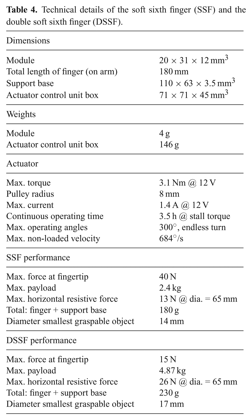
The final prototype of the robotic device is illustrated in Figure 8; the technical details are summarized in Table 4.
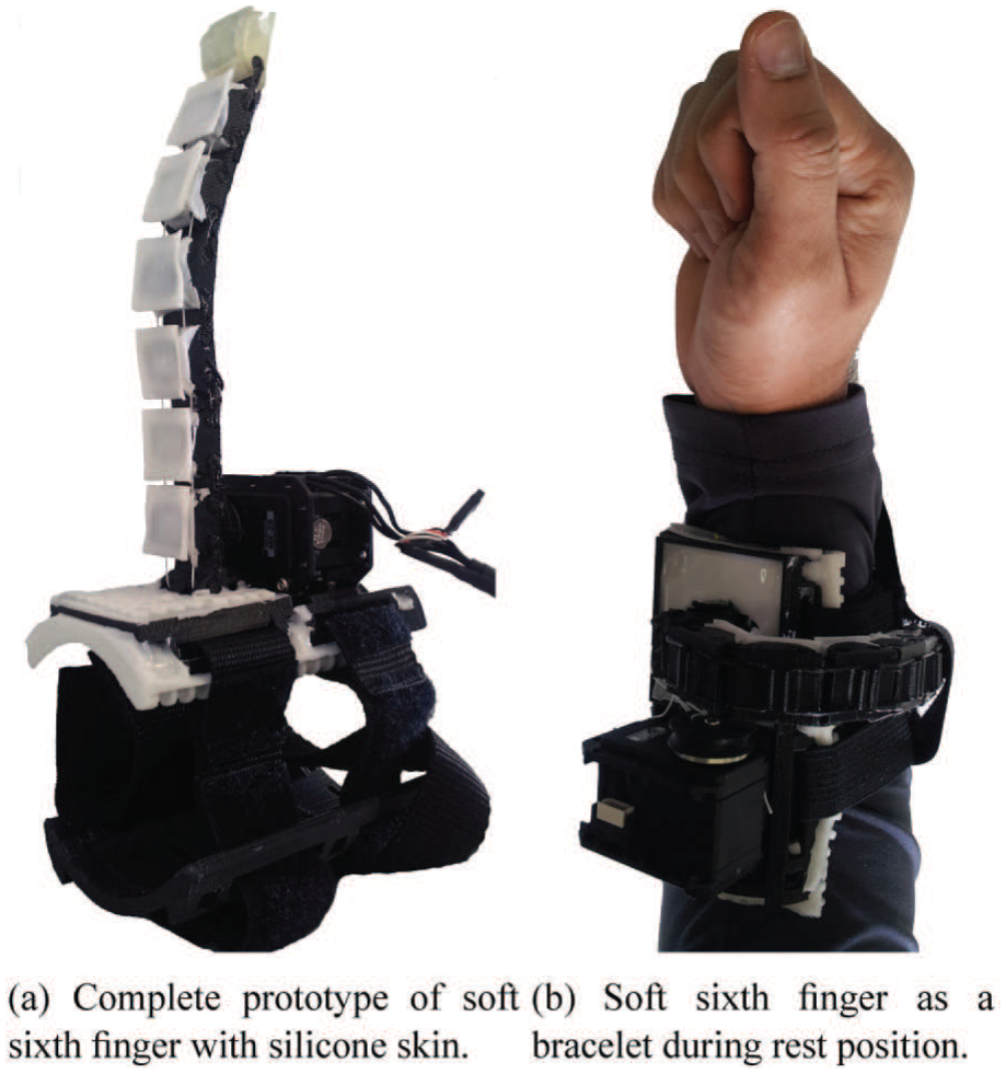
Complete prototype of the soft sixth finger with silicone skin. The device can be worn on the arm using an elastic band. It can be shaped as a bracelet when not in use to reduce the encumbrance of the device.
2.2.2. Performance characterization
The device performance was evaluated through a subset of the tests proposed by Falco et al. (2015). In particular, we measured the maximum fingertip force, the maximum payload, and maximum horizontal grasp resistive force.
The maximum fingertip force of the device was recorded while fixing its support base on a table with the finger perpendicular to the table surface. The initial configuration of the finger was fully extended and it was commanded to close at the maximum torque. The hook of a dynamometer (Vernier, USA) was rigidly coupled to the fingertip of the device so that force could be measured in the vertical direction, as shown in Figure 9(a). The constant applied force value at fingertip is presented in Table 4. The maximum horizontal grasp resistive force was measured by grasping an object (diameter, 65 mm; weight, 400 g) with the robotic device and the arm. The object was slowly pulled horizontally using the hook of the dynamometer, as shown in Figure 9(c). It was measured that the grasp remained stable up to 13 N. To check the maximum payload, an operator wore the grasp compensatory robotic device. The operator’s arm was stabilized on a table while grasping a cylindrical object (diameter, 65 mm; weight, 400 g) with the aid of the robotic tool at its maximum actuator’s torque. The grasped object was slowly pushed down using the dynamometer’s bumper, as shown in Figure 9(d). The maximum pushing force was recorded when the object started to slip. The maximum payload of the device (Table 4) is the sum of grasped object’s load and the load due to the pushing force. Figure 9(b) and (e) shows the smallest graspable objects. The diameter of the smallest graspable object is reported in Table 4.
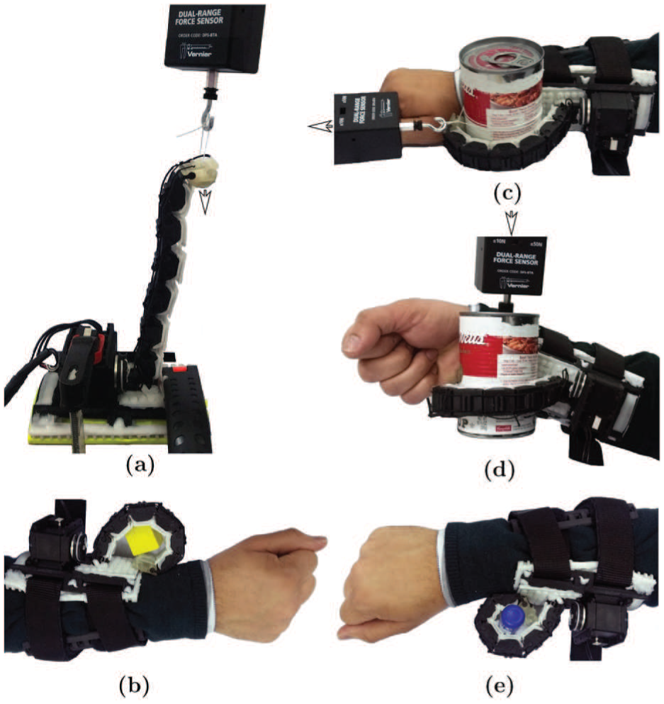
Procedure to measure the performance characteristics of the soft sixth finger. (a), (c), (d): experimental setup for maximum fingertip force, horizontal grasp resistive force, and maximum payload, respectively. The arrow shows the direction of applied force. (b) and (e): smallest graspable objects.
To prove the grasping ability of the device and its shape adaptability to different objects, we used a subset of the objects included in the YCB grasping toolkit (Çalli et al., 2015). This toolkit is intended to be used to facilitate bench-marking in prosthetic design, rehabilitation research, and robotic manipulation. The objects in the set are designed to cover a wide range of aspects of the manipulation problem. It includes objects of daily life with different shapes, sizes, textures, weight, and rigidities. We tested the device with different objects to evaluate how the robotic finger can adapt to the shape of the objects to realize a stable enveloping grasp. We mainly targeted the objects used in kitchen ADLs.
The tests were performed by a healthy subject wearing the device. This ensured that we only evaluated the shape adaptation of the device, avoiding possible grasp failure, which can occur as a result of low residual mobility of patients’ arms. The resulting grasps are shown in Figure 10. The finger was able to adopt itself to the shape of the grasped objects, owing to its intrinsic compliance.
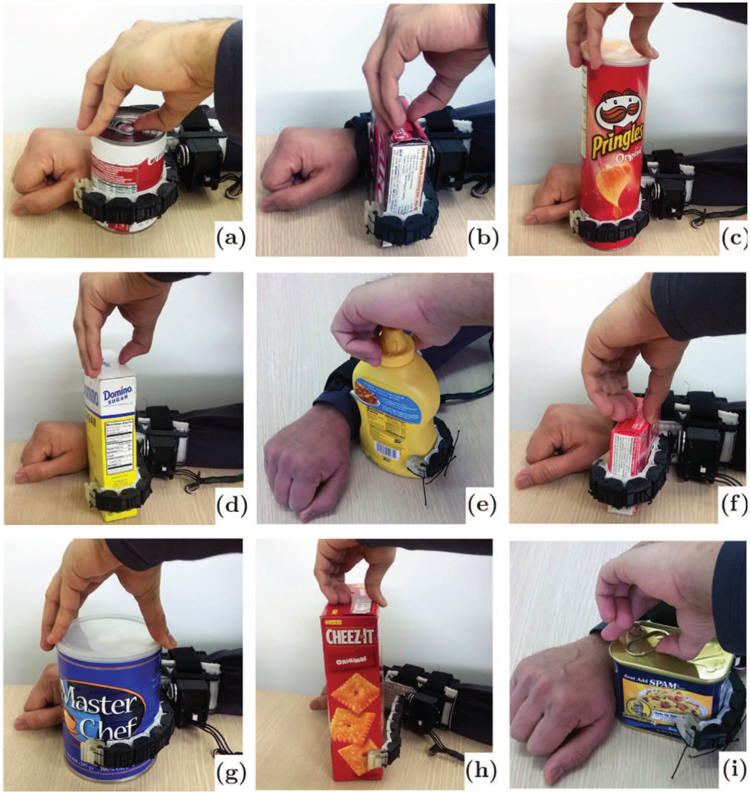
Soft sixth finger grasping various objects of different shapes and sizes: (a) tomato can, (b) chocolate pudding box, (c) chips can, (d) sugar box, (e) mustard bottle, (f) gelatin box, (g) coffee can, (h) cracker box, (i) meat can. The device is intrinsically compliant and adapts itself to the shape of the grasped object.
2.3. Double soft sixth finger
Although the soft sixth finger can be used to grasp and stabilize a large set of objects, having a single finger in opposition to the patient arm can result in a limitation in tasks requiring a high payload. We designed the double soft sixth finger to deal with these particular situations. The double soft sixth finger shares with the soft sixth finger the same principle design guidelines related to wearability, modularity, symmetrical structure, and underactuation. It is composed of three parts: a support base that allows the finger to be worn at the patient forearm and two fingers.
We fixed the fingers in a “V” configuration. The basic idea behind setting the two fingers in this configuration was to minimize the distance at the base of the fingers while maximizing the fingertips’ distance at the fully extended position for a given finger length. The rationale between this choice is the attempt to maximize the distance of the contact points at the fingertips when grasping relatively large objects. Thanks to the orientation of the finger at the base, when the fingers keep closing so to grasp smaller size objects, the fingertips of both fingers converge one toward the other; hence, minimizing the relative distance between them. Thus, this configuration is effective in grasping larger as well as smaller objects.
An exploded view of the unit module and the complete double soft sixth finger is shown in Figure 11. Two tendon wires (one for each flexible finger) and a single actuator control the motion of the device. One end of each tendon wire is fixed to each fingertip, while the other ends of both tendon wires are attached to a single pulley mounted on the shaft of the actuator (MX-28T).
Exploded CAD view of double soft sixth finger. Left: unit module with single tendon. Right: exploded view of complete double soft sixth finger.
When the motor rotates, both tendon wires are wound on the pulley and the fingers are flexed to grasp the object. As the motor is rotated in the opposite direction, the elastic parts in the joints restore the finger to its extended configuration. The final prototype of the device is shown in Figure 12. Also the double soft sixth finger can be worn on the arm using the base support and the Velcro strips. Both fingers can be shaped into a bracelet through two separate dovetail locking mechanisms when not in use.
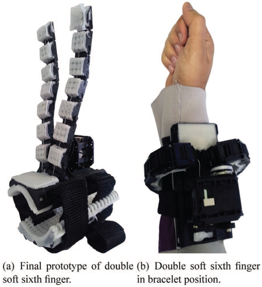
Final prototype of double soft sixth finger; the device can be worn on the paretic arm using the support base and elastic straps. It can be shaped into a bracelet when not being used.
We performed a similar evaluation for the double soft sixth finger to quantify its payload, maximum fingertip force, and horizontal grasp resistive force. The results are shown in Table 4. The approach of building a compensatory robotic device using two robotic fingers improves the payload and horizontal grasp resistive force, which in turn meas that the device can handle relatively heavier objects. The shape adaptation to the grasped object was also confirmed using the objects in the YCB toolkit.
2.4. Wearability and device positioning at forearm
The actuator’s controller and battery have been enclosed in a small box to be worn on the patient’s belt. Only the device and its actuator are placed at the patient’s forearm, to keep a minimum weight on it. The device can be put on by the user without assistance, simply by inserting the hand or arm between the two base parts. Then, using the Velcro elastic band, the patient can tighten the device at the forearm. The robotic devices can be wrapped around the arm as bracelets to reduce the encumbrance when not being used as shown in Figures 8(b) and 12(b). The patient can use his or her healthy hand to switch from the rest to the working position and vice versa. Switching between the two positions is achieved through a passive rotatable dovetail triangular locking mechanism. The mechanism consists of two parts, namely A and B. Part A is embedded on the support base while part B is contained in the finger starting module. After coupling both parts together, a pin joint has been added in the center of both parts to allow only rotation while constraining the decoupling of both parts without unscrewing the pin joint. The mechanism has two locking positions. The locking positions are set at the working and rest positions of the extra fingers. Apart from wearability and ergonomics, the device position at the forearm plays an important role in the task performance.
The location of the device depends on the patient conditions and on the residual mobility of the arm or hand. The compensatory robotic device can be worn on the distal part of the forearm (near or on the wrist), so as to obtain the grasp by opposing the device to the paretichand. However, the distal position of the robotic finger may fail when the motor deficit is so advanced that a pathological synergism in flexion has taken place. In this case, the wrist and fingers are too much flexed to allow successful grasping. When this pathological condition occurs, the extra finger may be positioned more proximal at the forearm, so to let the grasp be achieved by the extra fingers opposition to the radial part of the wrist (Figure 13). This flexibility in the positioning is achieved thanks to the symmetric structure and the ergonomics of the support base. The support base of the fingers can be translated or rotated along the forearm to place the finger on a suitable orientation. These features enable the device to adapt to the patient conditions and increase the versatility of the device. Moreover, the elastic straps along with Velcro enable the devices to fit to different sized arms and facilitates the patients in putting on the robotic device without assistance.
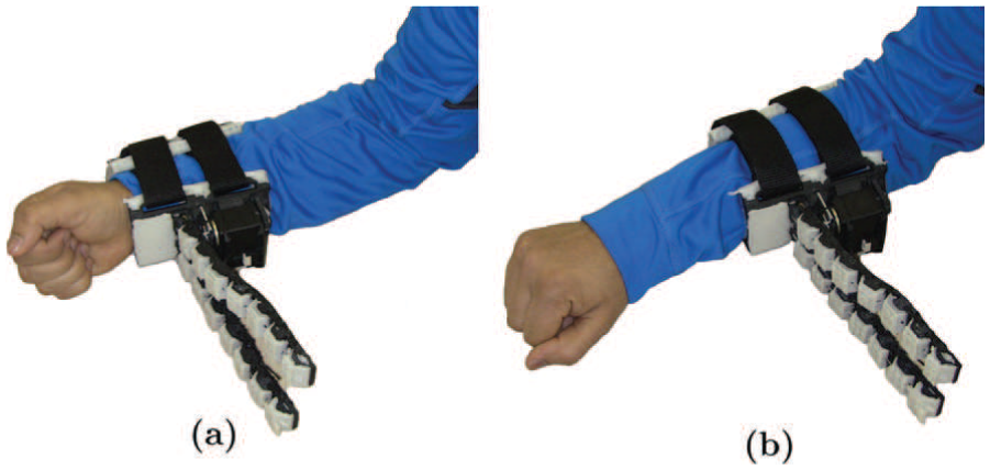
Two possible positions of grasp compensatory devices at the forearm: (a) the grasp is obtained at hand level by positioning the device at wrist position; (b) the grasp is obtained at forearm level by positioning the device near to the elbow. The ergonomic design of the support base allows the device to adapt to the patient’s condition to obtain a grasp at hand or forearm level.
3. Control interface
The control interface for patient-oriented devices must be intuitive and simple, since chronic patients may also be affected by some cognitive deficits, possibly limiting their compliance during a demanding learning phase. Coordinating the motion of the extra fingers with that of the hand where the devices are worn, as presented by Prattichizzo et al. (2014b) and Wu and Asada (2016), is not suitable for patients with hemiparetic upper limbs, since they are not able to control their hand motion. A possible solution could be the involvement of the contralateral hand in the control process. Ort et al. (2015) present a control strategy that maps the motion of the functional hand onto supernumerary robotic fingers. An instrumented glove is worn on the healthy hand to track its motion, while a mapping strategy is used to compute the motion of the robotic extra fingers. Hussain et al. (2015a,b) propose a ring embedding a push-button to control the motion of the extra robotic finger. The ring is worn on the healthy hand so to let the user activate it when necessary. However, preliminary experiments with patients revealed that these solutions limit the mobility and dexterity of the non-paretic hand and can also cause possible accidental activation of the device during ADLs. Patients also confirmed their preference of always having the healthy hand free during our preliminary tests.
To cope with this issue, we propose the eCap: an electromyography (EMG) based wireless interface, which maintains the principle of simplicity of a switch without interrupting the patient’s activities and without involvement of the healthy hand during task execution.
The eCap is a wireless EMG interface, in which electrodes, acquisition, and signal conditioning boards are embedded in a cap (Figure 14). A preliminary version of the control interface was presented by Hussain et al. (2016).
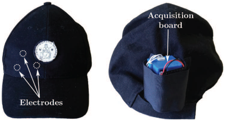
eCap interface. The EMG electrodes are placed inside the cap at the front side to be positioned on the patient’s forehead. The acquisition board is placed in a box on the back of the cap.
This solution allows the patient to put on the interface autonomously, using only the healthy hand. Several EMG interfaces have already been successfully adopted to control prostheses (Zecca et al., 2002) and exoskeletons (Kiguchi et al., 2004). The electrodes are usually placed either in the muscles coupled with the robot (exoskeleton) or in muscles where amputees still have the phantom of functions and hence are able to generate a repeatable EMG pattern corresponding to each of the functions (prosthesis). For chronic patients, it is generally difficult to generate repeatable EMG patterns in the paretic upper limb, owing to the weakness in muscle contraction control. For this reason, we coupled the flexion–extension motion of the robotic device with the contraction of the frontalis muscle. This muscle is always spared in the case of a motor stroke of either the left or the right hemisphere, owing to its bilateral cortical representation. The user can contract this muscle by moving the eyebrows upwards. The electrodes in the eCap capture the produced EMG signal, which is acquired through an EMG signal conditioning circuit and processed by a control algorithm, as explained next.
The EMG measures the electrical potential between a ground electrode and a sensor electrode. It is possible to measure signals either within the muscle (invasive EMG) or on the skin above a muscle (surface EMG) (Saponas et al., 2008).
We used surface EMG electrodes to measure electrical signals associated with the patient’s frontalis muscle. In particular, on the inner side of the eCap, we installed non-gelled reusable silver/silver-chloride electrodes, as they present the lowest noise interface and are recommended for biopotential recording (Merletti et al., 2009). We designed an EMG signal acquisition board, taking into consideration the requirements associated with bandwidth, dynamic range, and physiological principles. The typical EMG waveform is characterized with a spectral content of 10 –250 Hz with amplitudes up to 5 mV, depending on the particular muscle (Merlo and Campanini, 2010).
Figure15 shows a block diagram of the implemented EMG circuit board. Three electrodes are interfaced to the board: two of them (
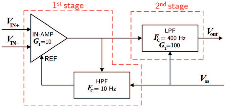
EMG circuit board.
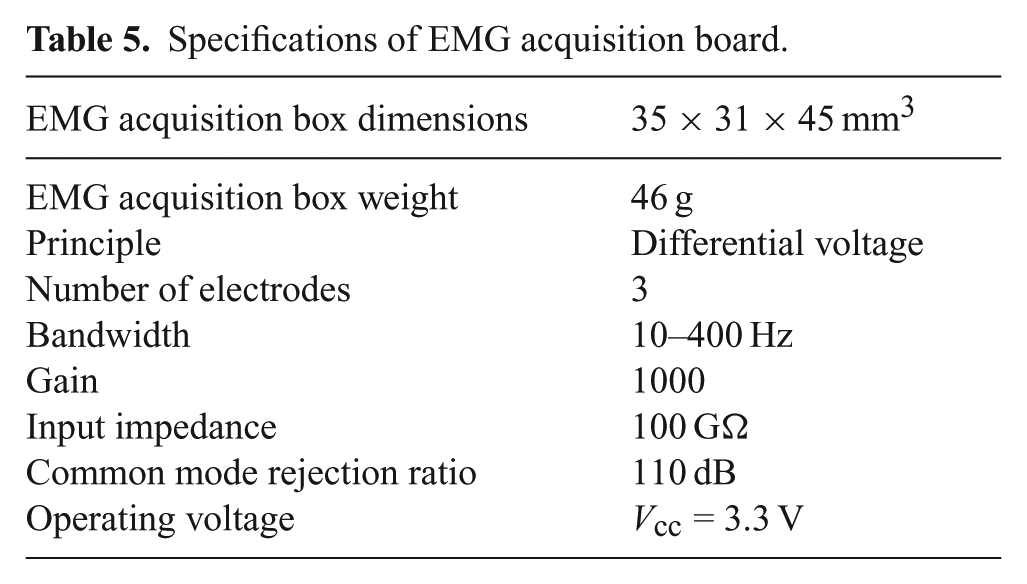
The first stage of the EMG board is an In-Amp with an additional stage of AC coupling. This configuration allows a precise control of DC levels, rejecting any undesired DC offset voltage introduced by the electrode–skin interface. The DC component is subtracted by feeding the output signal back to the reference input of the In-Amp, using an integrator feedback network, which results in a first-order high-pass response. The second stage of the EMG board is a fourth-order low-pass Butterworth filter. An active topology (a Sallen–Key circuit implementation—fourth-order low-pass filter cascading two stages of 2nd order) was chosen to give a better performance and less complexity than a passive one. The specifications of the EMG acquisition board are summarized in Table 5.
Specifications of EMG acquisition board.
The acquired EMG signal is sampled at 1 kHz (double EMG band) to avoid aliasing and a wireless communication is realized by a pair of Xbee modules (Series 1). The transmitter is embedded in the eCap, while the receiver is placed on the actuator controller unit. The reference value of the received EMG signals were normalized using a maximum voluntary contraction (MVC) technique (Farina and Merletti, 2000). This solution avoids problems related to the high influence of detection conditions on the EMG signal amplitude. In fact, the amplitude can vary greatly between electrode sites, subjects, and even day-to-day measurements of the same muscle site. We implemented an auto-tuning procedure based on the MVC technique to better match the user-dependent nature of the EMG signal. This is the major improvement with respect to the eCap version proposed by Hussain et al. (2016), where the sensitivity of the system was set manually using a potentiometer. The implemented MVC routine consists of a 3 s time window in which the users slowly start increasing the contraction of the forehead muscle to reach their maximum effort. The MVC value itself is not calculated as a single peak data point, to avoid high variability. To obtain a more stable reference value, we have implemented an algorithm using a sliding window technique of 500 ms duration to compute the mean amplitude of the highest signal portion acquired during the 3 s time window.
The motion of the compensatory robotic device is then controlled using a finite state machine based on a trigger signal (Oskoei and Hu, 2007). The trigger signal is obtained using a single-threshold value, defined as 50% of the MVC, a level that was repeatable and sustainable for the subject without producing undue fatigue during the use of the device. We set a minimum time (20 ms), in which the EMG signal must be constantly over the threshold to generate the trigger signal to prevent false activation due to glitches or spontaneous spikes. Figure 16 shows the raw EMG signal and the signal after the conditioning operations, i.e., rectification, normalization, and filtering. The red signal shown in the bottom graph of Figure 16 is the resultant trigger signal, which is generated if the EMG signal exceeds the threshold. The outputs of the finite state machine are predefined commands based on sequences of input signals. We consider a finite number of states, the transition between those states, and commands. States represent predefined motion commands for the robotic device and transition actions are associated with contractions of the frontalis muscle. The patients control the motion or stopping of the finger with a single muscle contraction (event e1). Once the finger is stopped, two contractions (event e2) in a time window of 1 s switch the direction of motion from flexion to extension and vice versa. The time window length was experimentally selected after repeated trials with patients and is in accordance with that proposed by Felzer and Freisleben (2002). A software-defined trigger (event e4) stops the actuator’s motion once the object is considered as grasped, to avoid a torque-overloading situation. The grasp confirmation is detected by continuously monitoring the actuator’s shaft position and the exerted torque. During the grasping procedure, if the position does not change in a time window of 2 s and a predefined torque threshold is reached, the object is considered grasped. The proposed finite state machine is reported in Figure 17.
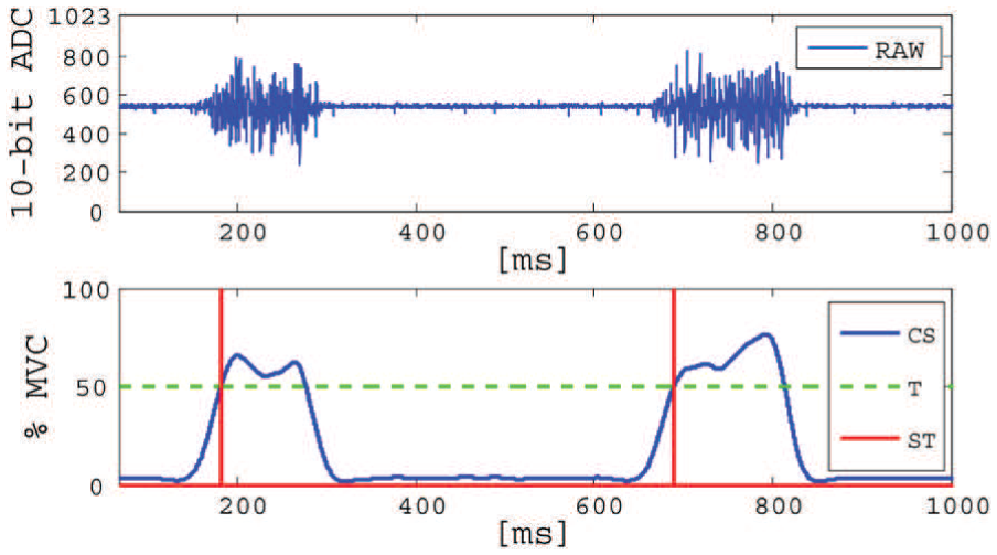
Top: raw EMG signal. Bottom: example of two activations in a time window of 1 s. CS (blue): processed EMG signal after rectification, normalization, and filtering; T (green): threshold; ST (red): resulting trigger.
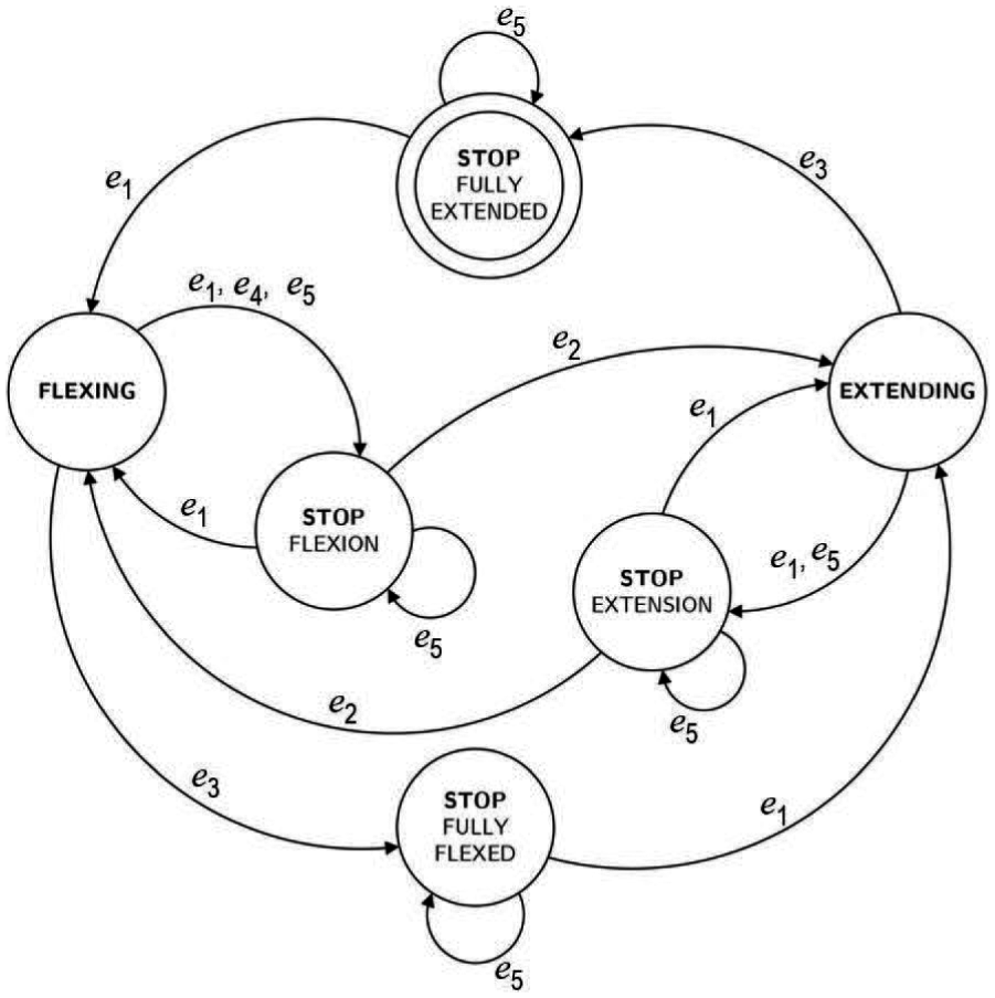
Proposed finite state machine for motion control of robotic devices. Events e1 and e2 are generated by the user, while e3 is a software-defined event. Event e4 occurs once the object is grasped. Event e5 activates switching between two proposed control interfaces (eCap or push-button).
An LED board (see Figure 18) is used to provide visual feedback of the selected commands. In particular, a yellow LED blinks on each trigger signal. When flexion is selected, an orange LED is turned on, while a green LED indicates extension. Finally, a red LED is turned on when the device is stopped. At this stage, the LED associated with the previous selected state is also turned on to remind the user of the last stage of the device. To provide an additional interface for the user, as well as a recovery mode for possible problems in the eCap communication, we added a push-button on the LED board as a further possible control.
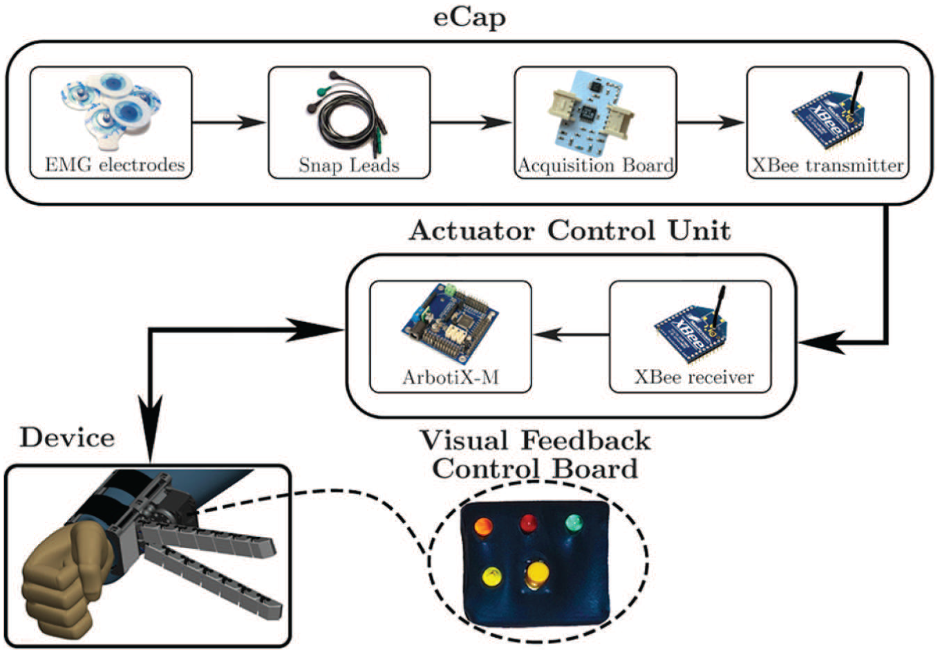
EMG wireless and push-button interface with actuator control unit. LEDs associated with the motion of the device are mounted on a visual feedback control board.
Both interfaces use the same trigger-based logical scheme to control the motion of the robotic devices. Switching between two control interfaces can be achieved at any moment by a toggle switch installed on the controller board. If the eCap is selected, the MVC procedure is first executed. Once it is completed, the program passes from calibration to test mode. If the push-button is selected, the control algorithm directly jumps to the test mode. In test mode, the user tests the selected interface by displaying the output on the LEDs mounted on the LED board to become familiar with the interface without using the robotic device. When the eCap control interface is selected, the user can repeat the MVC calibration (if needed) by simply pressing the push-button once. If the test mode output conforms to the expected program behavior and the user is ready to use the device, he or she can switch to the device mode, where motion of the robotic device is controlled according to the finite state machine shown in Figure 17. Switching from test to device mode is achieved by pressing the push-button for more than 1 s and is represented in the finite state machine in Figure 17 by the event e5. The process repeats every time the user switches to the other control interface.
4. Tests with chronic stroke patients
We performed a series of experiments with five chronic stroke patients (four men, one woman, aged 40–62) to prove the effectiveness of the devices in grasp compensation. Written informed consent was obtained from all participants. The procedures were in accordance with the Declaration of Helsinki. We targeted ADLs bimanual tasks to evaluate whether the compensatory robotic devices could assist the patients. To use the proposed devices, the subjects should have residual mobility of the arm. To be included in the experimental phase, patients had to score
The goal of the tests was to evaluate how quickly the patients could learn to use the devices and which device they preferred to fulfill a certain task. The patients were asked to select between the soft sixth finger and the double soft sixth finger to perform the proposed tasks. We recorded the time to complete the task in seconds for each task. Patients wore the robotic device on the paretic limb, on the left for two subjects and on the right for the other three. The rehabilitation team assisted the subjects during a training phase that lasted about 1 hour. During this phase, the optimal position of the device on the arm was evaluated according to the patient’s motor deficit. After the training phase, the subjects were asked to perform a list of bimanual tasks with the aid of proposed devices. We proposed to the patients three possible scenarios. The first included two different kitchen activities involving multiple bimanual tasks. In the second, we tested the device with bimanual tasks using tools. Finally, we tested the use of the robotic extra fingers to carry a shopping bag while walking.
4.1. Kitchen scenario
Cooking in the kitchen involves a variety of bimanual tasks and many of these are based on hold and manipulate techniques. The compensatory robotic devices can support the patients in performing such tasks, even if one hand is paretic. Figures 19 and 20 show snapshots of the tasks performed by the subjects to prepare breakfast and lunch.
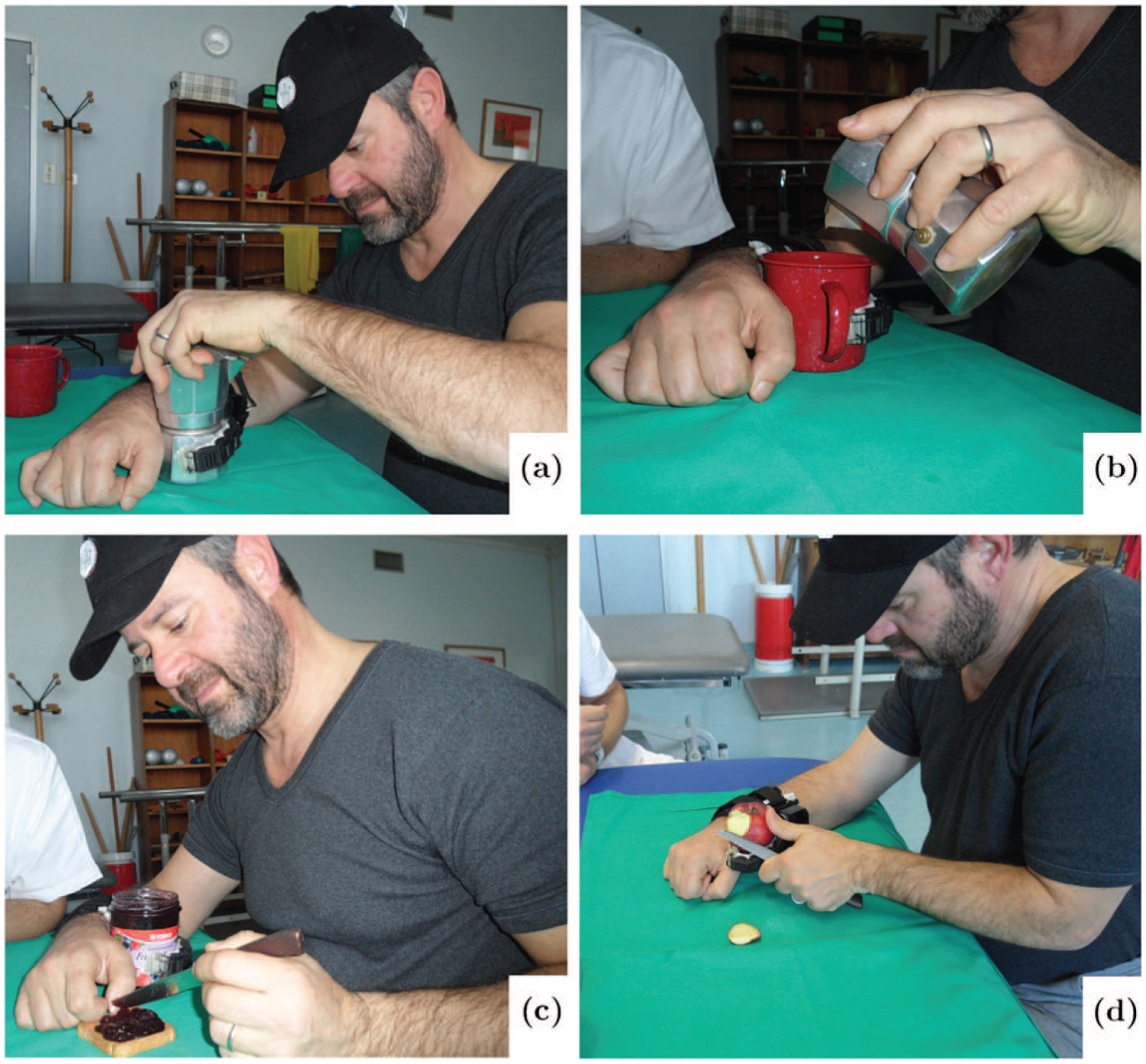
Preparing breakfast with the help of the grasping compensatory tool: (a) opening the moka pot; (b) pouring coffee into a cup; (c) spreading jam on bread; (d) peeling an apple.
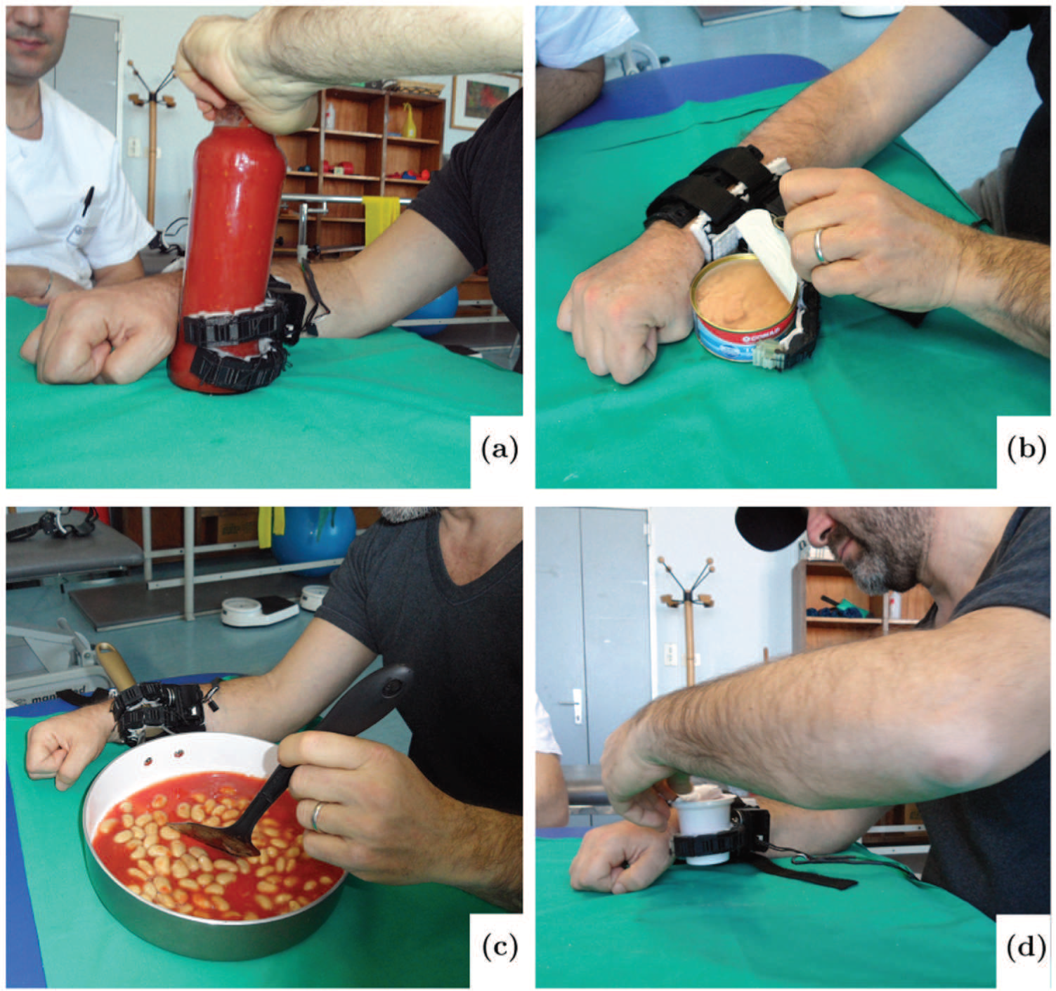
Preparing lunch with the help of the grasping compensatory robotic device: (a) opening tomato sauce bottle; (b) opening tuna can; (c) stirring food; (d) opening yogurt cup.
4.1.1. Preparing breakfast
We asked the patients to simulate the activities of preparing coffee, spreading jam on a slice of bread, and peeling an apple for breakfast.
Task 1 “Opening the coffee pot.” Hold the base of the coffee moka pot firmly with the help of the robotic device while using the healthy hand to unscrew the upper part (Figure 19(a)).
Task 2 “Closing the coffee pot.” Fill the filter with coffee grounds. Grasp the base part with the device and close the pot again.
Task 3 “Pouring coffee into a cup.” Pour coffee using the healthy hand while holding cup with the compensatory device (Figure 19(b)).
Task 4 “Opening the jam jar.” Grasp the jar with the device and non-functional arm while opening the cap with the functional one.
Task 5 “Spreading jam on bread.” Grasp the jam jar to take jam from it, holding the knife in the healthy hand. Spread jam on a slice of bread using the functional hand (Figure 19(c)).
Task 6 “Peeling apple.” Grasp the apple with the device and peel it using a knife in the healthy hand (Figure 19(d)).
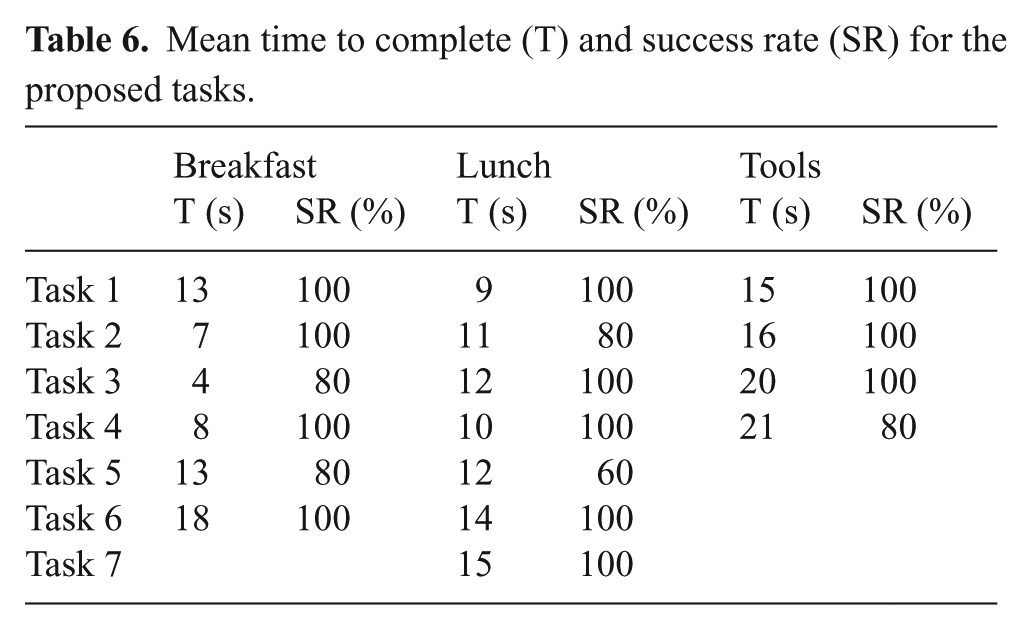
All the patients chose the soft sixth finger to perform the tasks, since the single finger was more suitable for manipulating relatively lightweight and smaller objects. Results on the time to complete the task and the success rate are reported in Table 6.
Mean time to complete (T) and success rate (SR) for the proposed tasks.
4.1.2. Preparing lunch
Task 1 “Opening tomato sauce bottle.” Constrain the motion of the jar with the device and the paretic arm while the healthy hand unscrews the cap (Figure 20(a)).
Task 2 “Pouring.” Pouring the tomato sauce from its bottle into a cooking pot.
Task 3 “Opening tuna can.” Hold the tuna can with the device while the functional hand opens the can (Figure 20(b)).
Task 4 “Opening bean can.” Constrain the motion of a bean can with the compensatory robotic device and the paretic arm while the healthy hand opens the cap.
Task 5 “Pouring.” Pouring the beans from the can into a cooking pot.
Task 6 “Stirring.” Hold the cooking pot firmly with the compensatory robotic device while the functional hand stirs the food in it (Figure 20(c)).
Task 7 “Opening yogurt cup.” Constrain the yogurt cup and remove its cover (Figure 20(d)).
All patients decided to use the double soft sixth finger to perform tasks (a) and (c), while the soft sixth finger was selected to complete tasks (b) and (d). Snapshots of the execution of the tasks are given in Figure 20. Results are reported in Table 6.
4.2. Tool activities
Tool activities are another example of ADLs where many tasks are based on a hold and manipulate principle. The presence of the compensatory robotic device can help the patient to complete such bimanual tasks even if one hand is non-functional. We asked the patients to use the tools to perform the following tasks.
Task 1: “Drilling in wood block.” Grasp the wood block with the device and impaired arm. Drill a hole in the wood block while using the drill in the healthy hand (Figure 21(a)).
Task 2: “Removing nail using claw hammer.” Hold the wood block firmly with the compensatory robotic device and the paretic arm. Use a claw hammer in the healthy hand to pull the nail from the wood block (Figure 21(b)).
Task 3: “Inserting tapping screw in the drilled hole.” Use the device and the paretic arm to hold the object with a drilled hole. Placing the tapping screw at the hole position, use the screwdriver with the functional hand to screw the screw until it is completely inserted in the hole (Figure 21(c)).
Task 4: “Tightening or loosening bolt using wrench key.” Constrain the object with the device and the paretic arm and use the wrench key in the healthy hand to tighten or loosen the bolt, (Figure 21(d)).
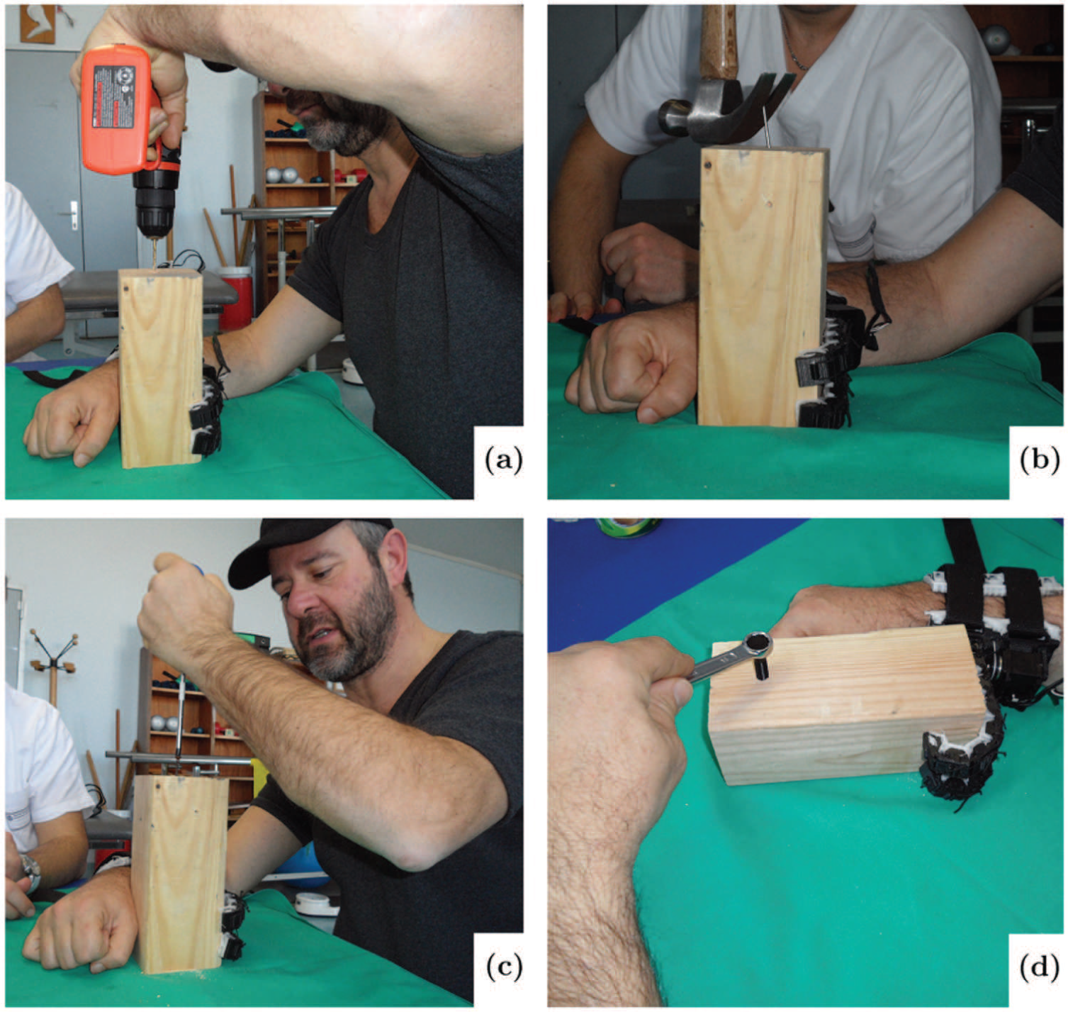
Using different tools in bimanual tasks with the aid of robotic device: (a) drilling in wood block; (b) removing nail using claw hammer; (c) inserting screw; (d) tightening or loosening bolt.
All patients selected the double soft sixth finger to perform the tasks. Results are reported in Table 6.
4.3. Active hook
The last application proposed was to carry a shopping bag with the compensatory robotic device while walking, as shown in Figure 22. The patients were successfully able to carry the bag using the robotic device on the paretic arm. As expected, the double soft sixth finger was able to carry a heavier bag than the soft sixth finger, owing to its higher payload. In particular, all the patients were able to carry a bag of 1.5 kg using the soft sixth finger and a bag of 3 kg using the double finger version.
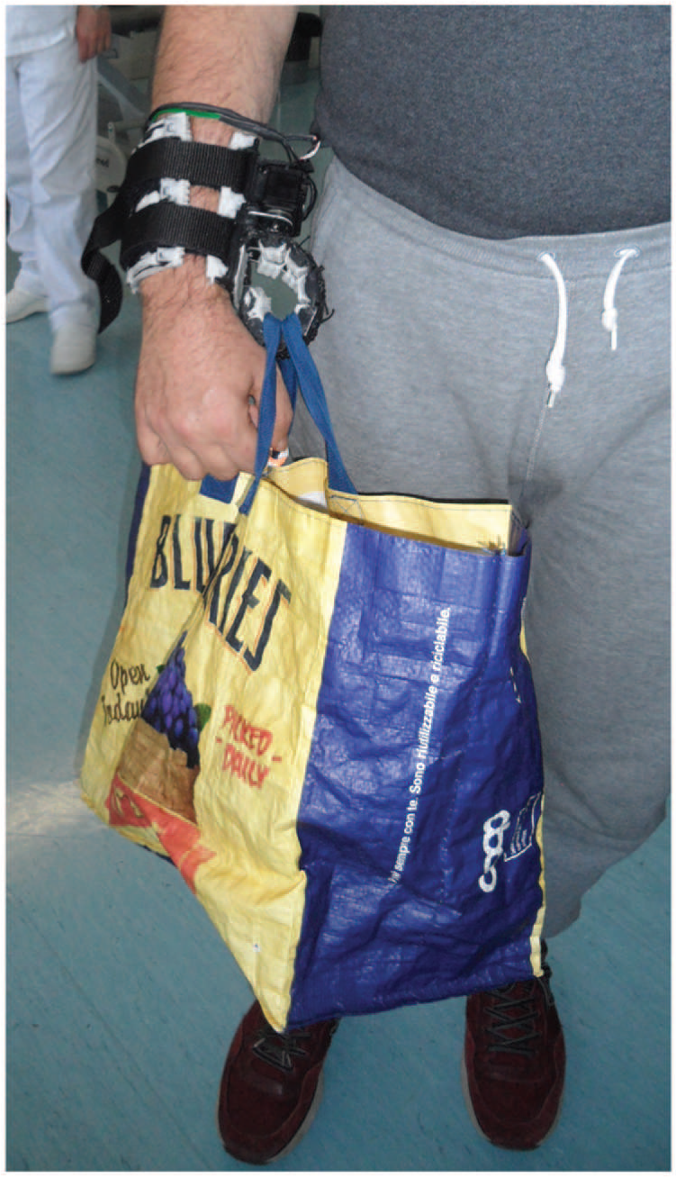
Carrying shopping bag with the help of grasping compensatory robotic device.
4.4. Questionnaires
After the experiments, we asked the patients about the usefulness and possible concerns related to the compensatory robotic devices for performing ADLs tasks. The patients were asked to complete the Usefulness-Satisfaction-and-Ease-of-use questionnaire (Lund, 2001), which focuses on the experience of using the system. This questionnaire uses a seven-point Likert rating scale. The results are presented in Table 7.
Questionnaire factors and relative marks. Marks range from “
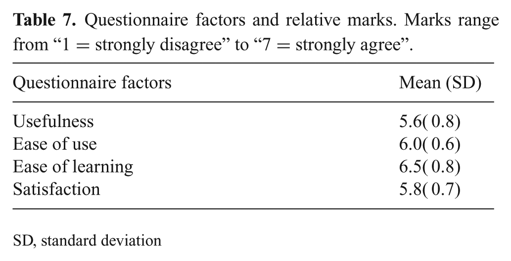
SD, standard deviation
Moreover, to evaluate the patient’s satisfaction with the proposed compensatory devices and their features, we asked the patients to complete the first part of the QUEST 2.0 questionnaire (Demers et al., 2002). The purpose of the QUEST questionnaire is to evaluate how satisfied patients are with the proposed assistive device. The mark ranges from “
Quebec User Evaluation of Satisfaction with Assistive Technology. Marks range from “
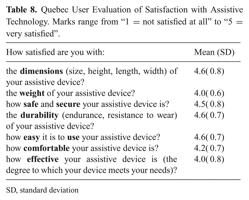
SD, standard deviation
5. Results and discussion
The ergonomics and functional requirements listed in Table 1 were considered in the design and development of the robotic devices. Table 2 summarizes the devices’ achieved requirements.
The robotic extra fingers were tested with different targets to demonstrate how the soft fingers can adapt to the shape of the object, producing a stable enveloping grasp. We recruited five chronic stroke patients to test the devices for use in ADLs. The proposed robotic devices successfully enabled the patients to complete the presented bimanual tasks. Failures in fulfilling the tasks. reported in Table 6, were mainly due to the weakness of the arm motion of one patient. The experiments authenticated that the presented robotic devices can be an effective aid for chronic stroke patients to perform simple ADLs tasks. The patients’ questionnaire feedback showed the effectiveness of the proposed compensatory robotic devices in assisting ADLs tasks.
The proposed robotic devices were an effective aid in completing the ADLs bimanual tasks. Compared with the old versions of the device, the soft sixth finger showed better performance, owing to the new actuation, the more stable support base, and increased friction at contact points. The realization of a new device, the double soft sixth finger, increased the potential use of compensatory devices in the ADLs tasks, since it is able to realize a more stable grasp in relatively more payload-demanding and pouring tasks. At this early stage of research, we cannot determine which device is better for fulfilling a certain task. The soft sixth finger was easier to use when it was necessary to grasp small objects. It is also more wearable and portable with respect to the version with two fingers. Conversely, the double soft sixth finger has a higher payload and can be used in more demanding manipulation tasks, such as pouring water from a bottle. This improvement in grasp stability comes at the cost of increased weight and reduced wearability. We believe that it is worth exploring both solutions in different applications and different tasks, and that it is worth developing the two platforms in collaboration with the clinicians and patients.
Although the experiments with patients showed the effectiveness of the devices in the completion of some ADLs, at the moment this approach has some limitations. Patients with hemiplegia or hemiparesis can vary over a wide range, from mild weakness and loss of dexterity in the fingers to complete paralysis in the left or right side of the body. Even if theproposed compensatory devices are able to compensate in terms of grasping, the use of the device requires some mobility in the impaired arm with the non-functional hand. Complex manipulation bimanual tasks, such as tying shoelaces or buttoning, are too demanding and beyond the scope of both the selected group of patients and the current devices. However, many ADLs tasks, including those presented in the paper, can successfully be completed with the aid of the proposed robotic devices.
6. Conclusions and future perspective
This paper presents the design, analysis, manufacture, experimental characterization, and evaluation of two prototypes of robotic extra fingers that can be used as grasp compensatory robotic devices for the hemiparetic upper limb. We tested the devices with chronic stroke patients through qualitative experiments based on ADLs.
Currently, we are investigating whether it is possible to introduce the robotic extra fingers in an early rehabilitation phase. Many of the rehabilitation strategies involve ADLs tasks where patients attempt to make use of the weak hand even though it is not functionally capable. This can result in feelings of frustration. Presenting an active compensatory tool may help in the initial phase to promote the use of the arm, even if the hand grasp function is not recovered. In a recent study (Hussain et al., 2017b), we presented a combination of a supernumerary robotic finger with a robotic arm support that can be used as an assistive device to support the patient’s arm weight. The overall proposed system can provide the needed assistance during paretic upper limb rehabilitation involving both grasping and arm mobility to solve task-oriented activities.
Finally, we are investigating the possibility of using our devices in patients affected by other neurological diseases possibly affecting hand grasping, such as multiple sclerosis, amyotrophic lateral sclerosis, and paresis due to cervical spinal cord lesions.
Footnotes
Appendix A: Index to multimedia extensions
Archives of IJRR multimedia extensions published prior to 2014 can be found at http://www.ijrr.org, after 2014 all videos are available on the IJRR YouTube channel at http://www.youtube.com/user/ijrrmultimedia.
This video presents the robotic extra fingers that can be used as grasp compensatory devices for hemiparetic upper limb. The devices are the results of experimental sessions with chronic stroke patients and consultations with clinical experts. Both devices share a common principle of work which consists in opposing to the paretic hand/wrist so to restrain the motion of an object. They can be used by chronic stroke patients to compensate for grasping in several Activities of Daily Living (ADL) with a particular focus on bimanual tasks. The robotic extra fingers are designed to be extremely portable and wearable. They can be wrapped as bracelets when not being used, to further reduce the encumbrance. Both devices are intrinsically compliant and driven by a single actuator through a tendon system. The motion of the robotic devices can be controlled using an Electromyography (EMG) based interface embedded in a cap. The interface allows the user to control the device motion by contracting the frontalis muscle. The performance characteristics of the devices have been measured through experimental set up and the shape adaptability has been confirmed by grasping various objects with different shapes. We tested the devices through qualitative experiments based on ADL involving five chronic stroke patients. The prototypes successfully enabled the patients to complete various bi-manual tasks. Results show that the proposed robotic devices improve the autonomy of patients in ADL and allow them to complete tasks which were previously impossible to perform.
Video
Appendix B: Kinematics modeling
To find the global coordinates of each module, we need to add the contributions from previous relative deflections and account for rotation due to the angle of the previous module. Homogeneous transformation matrices can be used to perform this operation. Let us consider a point described by
Where,
Acknowledgements
The authors are grateful to Dr. David Cioncoloni, Sabrina Taddei, and Professor Simone Rossi from the Dipartimento di Scienze Mediche, Chirurgiche e Neuroscienze, UOC Neurologia e Neurofisiologia Clinica, Brain Investigation, and Neuromodulation Laboratory (Si-BIN), Siena, Italy, for their suggestions and for help in recruiting and assisting the patient during the experiments.
Funding
The author(s) disclosed receipt of the following financial support for the research, authorship, and/or publication of this article: This work was supported by the European Union’s Horizon 2020 Research and Innovation Programme of the project “SoftPro: Synergy-based Open-source Foundations and Technologies for Prosthetics and RehabilitatiOn (grant number 688857)”.
References
Supplementary Material
Please find the following supplemental material available below.
For Open Access articles published under a Creative Commons License, all supplemental material carries the same license as the article it is associated with.
For non-Open Access articles published, all supplemental material carries a non-exclusive license, and permission requests for re-use of supplemental material or any part of supplemental material shall be sent directly to the copyright owner as specified in the copyright notice associated with the article.